Bloomfield Koffee-King 8540 Owner's Manual
Modular brewing systems
Hide thumbs
Also See for Koffee-King 8540:
- Specifications (2 pages) ,
- Brochure (34 pages) ,
- Installation use & care servicing instructions (28 pages)
Table of Contents
Advertisement
BLOOMFIELD INDUSTRIES
2 ERIK CIRCLE, P. O. Box 280
Verdi, NV 89439
Customer Service (775) 345-0444 Ext.502
fax: (775) 345-0569
www.wellsbloomfield.com
p/n 75804 Rev. (-)
OWNERS MANUAL
For
MODULAR
BREWING SYSTEMS
MODELS
POUR OVER
AUTOMATIC
UNITS
UNITS
8542
8541
8543
8573
8571
Includes:
Installation
Use & Care
Servicing Instructions
611
AUTOMATIC
UNITS
WITH FAUCET
8540
8572
8574
Model 8573 Brewers
with optional
8900-Series Glass Decanters
M611 011802 cps
Advertisement
Table of Contents

Related Manuals for Bloomfield Koffee-King 8540


Summary of Contents for Bloomfield Koffee-King 8540
-
Page 1: Servicing Instructions
BLOOMFIELD INDUSTRIES 2 ERIK CIRCLE, P. O. Box 280 Verdi, NV 89439 Customer Service (775) 345-0444 Ext.502 fax: (775) 345-0569 www.wellsbloomfield.com p/n 75804 Rev. (-) OWNERS MANUAL MODULAR BREWING SYSTEMS MODELS POUR OVER AUTOMATIC UNITS UNITS 8542 8541 8543 8573... -
Page 2: Warranty Statement
It also does not apply if the serial nameplate has been removed or unauthorized service personnel perform service. The prices charged by Bloomfield Industries for its products are based upon the limitations in this warranty. obligation under this warranty is limited to the repair of defects without charge by a Bloomfield Industries Authorized Service Agency or one of its sub-agencies. -
Page 3: Table Of Contents
120VAC 1ø 120VAC 1ø 120VAC 1ø 115/230VAC 1ø Thank You for purchasing this Bloomfield Industries appliance. Proper installation, professional operation and consistent maintenance of this appliance will ensure that it gives you the very best performance and a long, economical service life. -
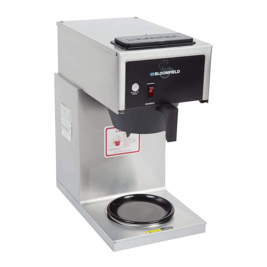
Page 4: Features & Operating Controls
FEATURES AND OPERATING CONTROLS Fig. 1 Features & Operating Controls... -
Page 5: Precautions & General Information
WARNING: Electric Shock Hazard All servicing requiring access to non-insulated components must be performed by qualified service personnel. Do not open any access panels which require the use of tools. Failure to heed this warning can result in electrical shock. WARNING: Injury Hazard All installation procedures must be performed by qualified personnel with full knowledge of all applicable electrical and plumbing codes. -
Page 6: Plumber's Installation Instructions
NOTE: Water supply inlet line must meet certain minimum criteria to insure successful operation of the brewer. Bloomfield recommends 1/4" copper tubing for installation of less than 25 feet and 3/8" for more than 25 feet from a 1/2" water supply line. - Page 7 NSF requires that the brewer be able to be moved for cleaning underneath. A flex line or loops of copper tubing will satisfy this requirement. See Figure 2 below. In some areas, local codes require a backflow preventer (check valve) to be installed on the inlet water line. If a backflow preventer is used, you must install a water hammer arrester in the incoming line, between the backflow preventer and the brewer inlet, as far away from the brewer as space will allow.
-
Page 8: Operation
OPERATION Fig. 4 Brewer Operation Diagram IMPORTANT: A. START-UP Tank must be full of water before connecting brewer to electrical power. Heating elements will be damaged if allowed to operate without being fully submerged in water. Damage caused by operating the brewer without water in the tank is NOT COVERED BY WARRANTY. -
Page 9: Water Heater
WATER HEATER Water temperature is sensed by a thermobulb inserted into the water tank. This temperature signal is fed to the thermostat, which controls line power to the heating element. The setpoint temperature is adjustable at the thermostat. The element is protected from over- temperature by a hi-limit thermostat. -
Page 10: Brewing Coffee
However, overuse of the faucet during a brew may lower the temperature of the brew water. B. PREPARATION Place one (1) genuine Bloomfield paper filter in the brew chamber. Add a pre-measured amount of fresh coffee grounds. Gently shake the brew chamber to level the bed of grounds. -
Page 11: Cleaning Instructions
PROCEDURE: Clean Coffee Brewer PRECAUTIONS: Disconnect brewer from electric power. Allow brewer to cool. FREQUENCY: Daily TOOLS: Mild Detergent, Clean Soft Cloth or Sponge Bristle Brush. 1. Disconnect brewer from electric power. Allow brewer to cool before cleaning. 2. Remove and empty decanters. 3. -
Page 12: Troubleshooting Suggestions
Repair/replace as needed Be sure to add sufficient water Increase water amount Adjust amount of grounds Adjust timer Use one (1) genuine Bloomfield filter per brew Thoroughly clean brew chamber Adjust coffee amount and grind Check/reinstall gasket on INSIDE of brew head... -
Page 13: Servicing Instructions
ACCESS PANELS Each warmer plate has a center stud which screws into a bracket. Remove warmer plates by turning counter-clockwise. Solenoid door is held by two screws and a retaining lip. Front Panel (In-Line Models) and Top / Rear Panel (3-Station Models): a. -
Page 14: Temperature Adjustment
SERVICING INSTRUCTIONS (continued) CAUTION Electric Shock Hazard These procedures involve exposed electrical circuits. These procedures are to be performed by qualified technical personnel only. NOTE: Optimum brewing temperature range is 195ºF to 205ºF (90ºC to 96ºC). IMPORTANT: A mechanical thermostat will maintain temperature within ±10ºF. -
Page 15: Timer Adjustment
TIMER ADJUSTMENT The amount of water dispensed automatically during a brew cycle is controlled by the timer. Place empty decanter under brew chamber. Press BREW button. Brewer should dispense one decanter of water. To adjust amount: Remove brew chamber and button plug. Adjust knob on timer; clockwise increases time. -
Page 16: Replace Solenoid
SERVICING INSTRUCTIONS (continued) Fig. 11 Clean Strainer Screen REPLACE SOLENOID Symptom: Automatic brewer will not flow water; or, automatic brewer drips continuously from brew head. Unplug power cord or turn circuit breaker OFF. Turn OFF and disconnect water supply from brewer inlet fitting. A. -
Page 17: Replace Timer Assembly
REPLACE TIMER ASSEMBLY Unplug power cord or turn circuit breaker OFF. Remove front panel. Remove knob and three screws holding timer to bracket. Disconnect wiring to timer. Reassemble in reverse order. Adjust timer as described on page 13 REPLACE HOT WATER FAUCET COIL Symptom: Brewer drips continuously from brew head, except when faucet valve is turned OFF. - Page 18 SERVICING INSTRUCTIONS (continued) CAUTION - CHEMICAL BURN HAZARD Deliming chemicals are caustic. Wear appropriate protective gloves and goggles during this procedure. Never siphon deliming chemicals or solutions by mouth. This operation should only be performed by qualified and ex- perienced service personnel. IMPORTANT: DO NOT spill, splash or pour water or deliming solution into or over any internal...
- Page 19 Run at least three full brew cycles and discard all water generated. 12. Brewer is ready to use. SERVICING INSTRUCTIONS (continued) NOTE: Normally, silicone hoses do not need to be delimed. Should deliming hoses become necessary, Bloomfield recommends replacing the hoses.
-
Page 20: Exploded Views & Parts Lists
EXPLODED VIEW & PARTS LIST CABINET & RELATED COMPONENTS... - Page 21 8942-6PP Brew Chamber, Portion Pack, Brown Filter Paper (case of 1000) EXPLODED VIEW & PARTS LIST (continued) USED ON 8540, 8541, 8572, 8573 & 8574 8540, 8541, 8572, 8573 & 8574 8574 8541, 8542, 8543, 8571, & 8573 8574 8540, 8541, 8572, 8573 & 8574 8540, 8541, 8543 8542, 8571, 8572, 8573 &...
- Page 22 No Coil - all parts mounted to cover) 8541WF-300 Spare Cover Assembly (120V, 1500W With Coil - all parts mounted to cover) USED ON 8540, 8572, 8574 8541, 8542, 8543, 8571, 8573 8540, 8572, 8574 All, except 8574 8574 All, except 8574...
-
Page 23: Electrical Components
Inlet Strainer (item 45-13) USED ON 8572, 8573, 8574 8540, 8541 All, except 8574 8574 All, except 8574 8540, 8541, 8572, 8573, 8574 8540, 8541, 8572, 8573, 8574 8541 & 8573 8540, 8572, 8574 All, except 8574 8574 All, except 8574... - Page 24 Spray Head Retainer Inlet Fitting, Straight (old-style) Coil Inlet “Tee” Fitting (old-style) Water Inlet Tube Elbow 1/4“ Male Flare x 1/4” FPT (old-style) 8540, 8541, 8572, 8573 & 8574 Solenoid Valve (old-style) Solenoid Valve, Single (new-style) Solenoid Valve w/ Bypass (new-style)
-
Page 25: Wiring Diagrams
WIRING DIAGRAMS... -
Page 26: Wiring Diagram
WIRING DIAGRAM... - Page 27 WIRING DIAGRAM (continued)
- Page 28 Division of Carrier Refrigeration PO. Box 280 Verdi, NV. 89439 Telephone (775)345-0444 Fax (888)492-2783 Service: (888)492-2782 website: www.wellsbloomfield.com Bloomfield Industries Canada Limited Division of Carrier Refrigeration 5850 Keaton Cresent Mississauga, Ontario, Canada L5R 3K2 Telephone (905)507-1700 Fax (905)507-1777 Toll Free (877)507-1700 website: www.bloomcan.com...
Need help?
Do you have a question about the Koffee-King 8540 and is the answer not in the manual?
Questions and answers