
Related Manuals for Lenze E82ZAFPC010


Summary of Contents for Lenze E82ZAFPC010
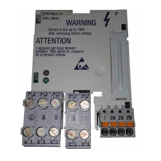
- Page 1 EDK82ZAFPC-010 .C$Y Montageanleitung Mounting Instructions Instructions de montage PROFIBUS PT E82ZAFPC010 Funktionsmodul Function module Module de fonction ...
- Page 2 Legend for fold-out page Pos. Description Detailed information DIP switch for activating the bus terminating resistor 68 70 Status of PROFIBUS communication (yellow LED) Connection status to the standard device (green LED) 61 Plug connector X3.1, connection for PROFIBUS ...
-
Page 3: Table Of Contents
Contents About this documentation ......... . . Conventions used . -
Page 4: About This Documentation
This documentation includes ... ƒ Safety instructions which you must observe in any case; ƒ Data about the versions of Lenze basic devices to be used; ƒ Information about the mechanical and electrical installation of the function module; ƒ Information about the commissioning of the function module;... -
Page 5: Conventions Used
About this documentation Conventions used Conventions used This documentation uses the following conventions to distinguish between different types of information: Type of information Identification Examples/notes Numbers Decimal separator Point The decimal point is used throughout this documentation. Example: 1234.56 Symbols Page reference ... -
Page 6: Notes Used
About this documentation Notes used Notes used The following pictographs and signal words are used in this documentation to indicate dangers and important information: Safety instructions Structure of safety instructions: Danger! (characterises the type and severity of danger) Note (describes the danger and gives information about how to prevent dangerous situations) Pictograph and signal word... - Page 7 About this documentation Notes used Application notes Pictograph and signal word Meaning Important note to ensure troublefree operation Note! Useful tip for simple handling Tip! Reference to another documentation EDK82ZAFPC-010 DE/EN/FR 6.0...
-
Page 8: Safety Instructions
Safety instructions Safety instructions Danger! Inappropriate handling of the function module and the standard device can cause serious injuries to persons and damage to material assets. Observe the safety instructions and residual hazards included in the documentation of the standard device. ... -
Page 9: Product Description
The function module connects Lenze frequency inverters to the serial PROFIBUS communication system. Application as directed The function module ... ƒ is an accessory module for use in conjunction with the following Lenze standard devices: Product range Device identification From hardware version... -
Page 10: Scope Of Supply
Scope of supply E82ZAFL012C/AFX007/010/016/020 Pos. Scope of supply E82ZAFPC010 function module Mounting Instructions Plug connector with double screw connection, 3-pole Plug connector with double screw connection, 2-pole Plug connector with spring connection, 4-pole Mounting clip ... -
Page 11: Identification
Product description Identification Identification ‚ƒ ‚ƒ 010 / 3A22 APPLICATION APPLICATION 010 / 3A22 010 / 3A22 010 / 3A22 Type Id.-No. Prod.-No. Ser.-No. E82AF000P0B201XX E82ZAFX005 E82ZAF Product series PROFIBUS Version Variant: PT (Plug Terminal) with spring and screw connection Hardware version Software version ... -
Page 12: Technical Data
Technical data General Data Technical data General Data Field Values Order designation E82ZAFPC010 PUO ID number 0x00DA Communication profile PROFIBUS-DP (DIN 19245 part 1 and part 3) Communication medium RS485 Drive profile DRIVECOM profile ”Power Transmission 20”, can be switched off... -
Page 13: Operating Conditions
1K3 (-25 to +60 °C) Transport IEC/EN 60721-3-2 2K3 (-25 to +70 °C) Operation Corresponding to the data of the Lenze standard device used (see documentation of the standard device). Pollution EN 61800-5-1 Degree of pollution 2 Degree of protection... -
Page 14: Dimensions
Technical data Dimensions Dimensions E82ZAFP007 EDK82ZAFPC-010 DE/EN/FR 6.0... -
Page 15: Mechanical Installation
Mechanical installation Mechanical installation Follow the notes given in the Mounting Instructions for the standard device for the mechanical installation of the function module. The Mounting Instructions for the standard device ... ƒ are part of the scope of supply and are enclosed with each device. ƒ... -
Page 16: Electrical Installation
Electrical installation Use of plug connectors Electrical installation Use of plug connectors Stop! Observe the following to prevent any damage to plug connectors and contacts: Only pug in / unplug the plug connectors when the controller is ƒ disconnected from the mains. Wire the plug connectors before plugging them in. -
Page 17: Wiring According To Emc
Electrical installation Wiring according to EMC Wiring according to EMC For wiring according to EMC requirements observe the following points: Note! Separate control cables/data lines from motor cables. ƒ Connect the shields of control cables/data lines at both ends in the case of ƒ... -
Page 18: Wiring To A Host
Wiring to a host Danger! Dangerous electrical voltage If Lenze controllers are used on a phase earthed mains with a rated mains voltage ≥ 400 V, protection against accidental contact is not ensured without implementing external measures. Possible consequences: Death or serious injury ƒ... - Page 19 Electrical installation Wiring to a host The connection of the PROFIBUS bus system is shown in the general layout drawing. 8200 vector 8200 vector 8200 vector E82ZAFPC010 E82ZAFPC010 E82ZAFPC010 1200 m E82ZAFP005 Fig. 1 Example: PROFIBUS with RS485 wiring (without repeater)
- Page 20 Electrical installation Wiring to a host Specification of the transmission cable Note! Only use cables complying with the listed specifications of the PROFIBUS user organisation. Field Values Ω Specific resistance 135 ... 165 /km, (f = 3 ... 20 MHz) ≤...
-
Page 21: Bus Cable Length
Electrical installation Bus cable length Bus cable length The length of the bus cable depends on the baud rate used: Baud rate [kbps] Length [m] 9.6 ... 93.75 1200 187.5 1000 1500 3000 ... 12000 Note! The baud rate depending on the data volume, cycle time, and number of nodes should only be selected as high as required for the application. -
Page 22: Voltage Supply
Electrical installation Voltage supply Voltage supply Internal DC voltage supply The internal voltage is provided at terminal X3.3/20. It serves to supply the controller inhibit (CINH). T/R(A) T/R(B) GND1 GND1 GND2 +20V X3.1 X3.2 X3.3 T/R(A) T/R(B) E82ZAFP011 The min. wiring requirements for operation ... - Page 23 Electrical installation Voltage supply External voltage supply Note! Always use a separate power supply unit in every control cabinet and safely separate it according to EN 61800-5-1 (”SELV”/”PELV”) in the case of external voltage supply and larger distances between the control cabinets. External voltage supply of the communication module is required if communication via the fieldbus is to be maintained even when the power supply of the standard device fails.
- Page 24 Electrical installation Voltage supply External voltage supply with two voltage sources for 1. X3.3/28 (controller inhibit (CINH)) 2. X3.2/59 (function module) T/R(A) T/R(B) GND1 GND1 GND2 +20V X3.1 X3.2 X3.3 T/R(A) T/R(B) E82ZAFP013 The min. wiring requirements for operation EDK82ZAFPC-010 DE/EN/FR 6.0...
-
Page 25: Assignment Of The Terminals
Electrical installation Assignment of the terminals Assignment of the terminals Terminal Designation Function / level X3.1/ Additional HF shield termination T/R(A) RS485 data line A T/R(B) RS485 data line B Terminal Designation Function / level X3.2/ External DC voltage supply for the function module ±... -
Page 26: Cable Cross-Sections And Screw-Tightening Torques
Electrical installation Cable cross-sections and screw-tightening torques Cable cross-sections and screw-tightening torques Field Values Electrical connection Plug connector with double screw connection Possible connections rigid: 1.5 mm (AWG 16) flexible: without wire end ferrule 1.5 mm (AWG 16) with wire end ferrule, without plastic sleeve 1.5 mm (AWG 16) with wire end ferrule, with plastic sleeve... -
Page 27: Commissioning
Commissioning Before switching on Commissioning Before switching on Stop! Before switching on the standard device with the function module for the first time, check... the entire wiring for completeness, short circuit, and earth fault. ƒ whether the integrated bus terminating resistor is activated at the first ƒ... -
Page 28: Commissioning Steps
(only visible in the case of 8200 vector). Keypad: (if plugged in) Activate bus terminating resistor via DIP switch = ONfor the first and 68 last node. Lenze setting: OFF EDK82ZAFPC-010 DE/EN/FR 6.0... - Page 29 Assign process data output words (POW) of the master to process communication data input words of the standard device via C1511. manual Lenze setting: POW1: DRIVECOM control word (DRIVECOM CTRL) POW2: Setpoint1 (NSET1-N1) POW3: Setpoint2 (NSET1-N2) POW4: Additional setpoint (PCTRL1-NADD)
- Page 30 Assign process data output words of the standard device to the communication process data input words (PIW) of the master via C1510. manual Lenze setting: PIW1: DRIVECOM status word (DRIVECOM STAT) PIW2: Output frequency with slip (MCTRL1-NOUT+SLIP) PIW3: Output frequency without slip (MCTRL1-NOUT)
-
Page 31: Configuring The Host System
For configuring the PROFIBUS, the device data base file (GSE file) of the communication module has to be imported into the configuring software of the master. Tip! The GSE file can be downloaded in the ”Services & Downloads” area at www.Lenze.com. EDK82ZAFPC-010 DE/EN/FR 6.0... -
Page 32: Activating The Bus Terminating Resistor
Commissioning Activating the bus terminating resistor Activating the bus terminating resistor The integrated bus terminating resistor can be activated with the DIP switch . E82ZAFP016 / E82ZAFP010 DIP switches Switch position Function Bus terminating resistor not active. Bus terminating resistor active. ... -
Page 33: Connecting The Mains Voltage
- in some cases - even not allowed. The restart behaviour of the controller can be set in C0142: C0142 = 0 (Lenze setting) ƒ – The controller remains inhibited (even if the fault is no longer active). -
Page 34: Diagnostics
Diagnostics LED status displays Diagnostics LED status displays E82ZAFPC010 E82ZAFP016 Pos. Colour Condition Description yellow No communication with the PROFIBUS master. blinking Communication with the PROFIBUS master has been established via the function module. green The function module is not supplied with voltage.
Need help?
Do you have a question about the E82ZAFPC010 and is the answer not in the manual?
Questions and answers