
Related Manuals for Lenze E82ZAFPC201


Summary of Contents for Lenze E82ZAFPC201
- Page 1 EDS82ZAFPC201 L−force Communication .IFG Communication Manual PROFIBUS I/O E82ZAFPC201 Function module...
-
Page 2: Table Of Contents
Contents About this documentation ..........Document history . - Page 3 ....... 8.1.2 Addressing of the Lenze parameters ......
- Page 4 ..............12.1 Particularities for use in conjunction with Lenze standard devices .
-
Page 5: About This Documentation
– Safety instructions which must be observed. – The essential technical data of the function module – Information on versions of the Lenze standard devices to be used – Notes on troubleshooting and fault elimination The theoretical concepts are only explained to the level of detail required to understand the function of the function module. -
Page 6: Document History
This documentation is intended for all persons who plan, install, commission and maintain the networking and remote service of a machine. Tip! Information and auxiliary devices related to the Lenze products can be found in the download area at http://www.Lenze.com Document history Material no. -
Page 7: Conventions Used
The term stands for the PROFIBUS−DP variant according to IEC 61158 / IEC 61784. A different PROFIBUS variant is not described in these Instructions. Standard device Lenze controllers/frequency inverters with which the communication module can be used. Controller ^ 11... -
Page 8: Notes Used
About this documentation Notes used Notes used The following pictographs and signal words are used in this documentation to indicate dangers and important information: Safety instructions Structure of safety instructions: Danger! (characterises the type and severity of danger) Note (describes the danger and gives information about how to prevent dangerous situations) Pictograph and signal word Meaning... -
Page 9: Safety Instructions
The manufacturer does not accept any liability for the suitability of the specified procedures and circuit proposals. Only qualified skilled personnel are permitted to work with or on Lenze drive and ƒ... -
Page 10: Device− And Application−Specific Safety Instructions
Safety instructions Device− and application−specific safety instructions Device− and application−specific safety instructions During operation, the function module must be firmly connected to the standard ƒ device. With external voltage supply, always use a separate power supply unit, safely ƒ separated to EN 61800−5−1 ("SELV"/"PELV"), in every control cabinet. Only use cables corresponding to the given specifications (¶... -
Page 11: Product Description
Product description Application as directed Product description Application as directed The function module ... is an accessory module for use in conjunction with the following Lenze standard ƒ devices: Product range Device designation From hardware version Frequency inverter 8200 vector... -
Page 12: Product Features
Product features Product features Interface module for the PROFIBUS communication system which can be connected ƒ to the AIF slots of the Lenze 8200 vector and 8200 motec device series Support of communication profiles PROFIBUS−DP−V0 and PROFIBUS−DP−V1 ƒ Drive profiles: ƒ... -
Page 13: Connections And Interfaces
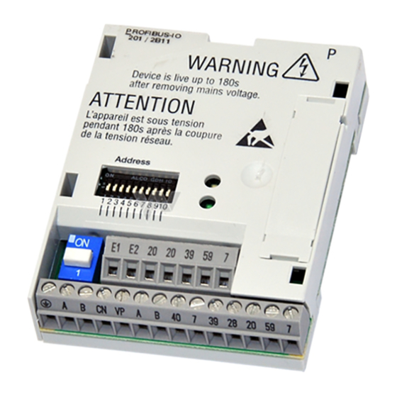
Product description Connections and interfaces Connections and interfaces E82ZAFP020B / E82ZAFX009 Fig. 3−1 Communication module E82ZAFPC201 (PROFIBUS I/O) Pos. Description Detailed information ^ 85 Status of PROFIBUS communication (yellow LED) Connection status to standard device (green LED) DIP switches for setting ... -
Page 14: Technical Data
1K3 (−25 to +60 °C) Transport IEC/EN 60721−3−2 2K3 (−25 to +70 °C) Operation Corresponding to the data of the Lenze standard device used (see documentation of the standard device). Pollution EN 61800−5−1 Degree of pollution 2 Degree of protection IP20 (protection against accidental contact according to NEMA 250 type 1) EDS82ZAFPC201 EN 4.0... -
Page 15: Protective Insulation
Protective insulation Protective insulation Danger! Dangerous electrical voltage If Lenze controllers are used on a phase earthed mains with a rated mains voltage ³ 400 V, protection against accidental contact is not ensured without implementing external measures. Possible consequences: Death or serious injury ƒ... -
Page 16: Communication Time
Technical data Communication time Terminal Designation Function / level X3.2/ Additional HF shield termination T/R(A) RS485 data line A T/R(B) RS485 data cable B CNTR For function see PROFIBUS standard *) Level during data transmission: CNTR = HIGH (+5 V DC, reference: GND3) For function see PROFIBUS standard *) U = +5 V DC (reference: GND3) = 10 mA... -
Page 17: Dimensions
Technical data Dimensions Dimensions E82ZAFP020C 51 mm 64 mm 15 mm EDS82ZAFPC201 EN 4.0... -
Page 18: Installation
Installation Mechanical installation Installation Danger! Inappropriate handling of the function module and the standard device can cause serious injuries to persons and damage to material assets. Observe the safety instructions and residual hazards included in the documentation of the standard device. Stop! The device contains components that can be destroyed by electrostatic discharge! -
Page 19: Electrical Installation
Installation Electrical installation Wiring according to EMC (CE−typical drive system) Electrical installation 5.2.1 Wiring according to EMC (CE−typical drive system) For wiring according to EMC requirements observe the following points: Note! Separate control cables/data lines from motor cables. ƒ Connect the shields of control cables/data lines at both ends in the case of ƒ... -
Page 20: Wiring With A Host (Master)
Basic design of a PROFIBUS network with RS485 cabling without repeater starttec starttec starttec 8200 vector 8200 vector 8200 vector 8200 motec 8200 motec 8200 motec E82ZAFPC201 E82ZAFPC201 E82ZAFPC201 1200 m E82ZAFP005 Element Note Host E.g. PC or PLC with PROFIBUS master interface module Bus cable Connects the PROFIBUS master interface module to the function modules. - Page 21 Installation Electrical installation Wiring with a host (master) Number of bus devices 2133PFB004 Segment Master (M) Slave (S) Repeater (R) − − − − Tip! Repeaters do not have a device address. When calculating the maximum number of bus devices, they reduce the number of devices by 1 on each side of the segment.
- Page 22 Installation Electrical installation Wiring with a host (master) Specification of the transmission cable Note! Only use cables complying with the listed specifications of the PROFIBUS user organisation. Field Values 135 ... 165 W/km, (f = 3 ... 20 MHz) Specific resistance £...
-
Page 23: Voltage Supply
Installation Electrical installation Voltage supply 5.2.3 Voltage supply Internal DC voltage supply The internal voltage is available at terminal X3.1/20 or X3.2/20. It supplies the controller inhibit (CINH) and the digital inputs E1/E2. GND1 GND1 GND1 +20V GND2 GND3 GND2 +20V... -
Page 24: Terminal Assignment
Installation Electrical installation Terminal assignment External voltage supply via two voltage sources: X3.1/E1 and X3.1/E2 (digital inputs) and ƒ X3.2/28 (controller inhibit (CINH)) X3.2/59 (function module) ƒ E82ZAFP002 (V201) Minimum wiring required for operation 5.2.4 Terminal assignment Terminal Designation Function / level X3.1/ Digital inputs *) Adapt the individual setting via C0007 or C0410. -
Page 25: Cable Cross−Sections And Screw−Tightening Torques
Installation Electrical installation Cable cross−sections and screw−tightening torques Terminal Designation Function / level X3.2/ Additional HF shield termination T/R(A) RS485 data line A T/R(B) RS485 data cable B CNTR For function see PROFIBUS standard *) Level during data transmission: CNTR = HIGH (+5 V DC, reference: GND3) For function see PROFIBUS standard *) U = +5 V DC (reference: GND3) -
Page 26: Commissioning
In Lenze devices, this is done via codes. The codes are stored in numerically ascending order in the Lenze controllers and in the plugged−in communication/function modules. In addition to these configuration codes, there are codes for diagnosing and monitoring the bus devices. -
Page 27: Commissioning Steps
DIP switch S8 = OFF ^ 33 Activate the bus terminating resistor of the first and last bus device through DIP switch = ON. Lenze setting: OFF ^ 33 A Set the bus device address via ... – C1509 or –... - Page 28 Detailed information Use C1511 to assign the process data output words (POW) of the master to the process data input words of the standard device. Lenze setting: POW1: DRIVECOM control word (DRIVECOM−CTRL) POW2: Setpoint1 (NSET1−N1) POW3: Setpoint2 (NSET1−N2) POW4: Additional setpoint (PCTRL1−NADD) POW5: Actual process controller value (PCTRL1−ACT)
-
Page 29: Configuring The Host System (Master)
For configuring the PROFIBUS, the device data base file (GSE file) of the communication module has to be imported into the configuring software of the master. Tip! The GSE file can be downloaded from www.Lenze.com. Device data base file The device data base file LENZ081B.GSE contains the following configurations:... - Page 30 Commissioning Configuring the host system (master) Setting compatibility with PPO types 1 ... 5 6.3.1 Setting compatibility with PPO types 1 ... 5 Process data assignment of PPO types: Type Selection text in LENZ08IB.GSE PPO1 PKW (cons) PZD (2 words) PKW (cons) PZD (2 words cons) PPO2...
-
Page 31: Adapting Device Controls
– Set C1511/1 (POW1) = 1 ð FIF control word 1 (FIF−CTRL1) – Set C1510/1 (PIW1) = 1 ð FIF status word 1 (FIF−STAT1) Device control via DRIVECOM (Lenze setting) ƒ – Set C1511/1 (POW1) = 17 ð DRIVECOM control word (DRIVECOM−CTRL) –... -
Page 32: Setting The Software Compatibility
0 Byte 1 Word Consistency 0 Byte or word 1 Total length Setting the software compatibility DIP switch S8 (2) serves to set compatibility with the Lenze PROFIBUS function modules E82ZAFPC0xx. E82ZAFP020B 9 10 E82ZAFD005 DIP switch 2 Position of switch S8... -
Page 33: Activating The Bus Terminating Resistor
If the addresses 0, 1, 2, 126 or 127 are set, the settings from code C1509 become active. 6.6.1 Setting via code DIP switches S1 ... S7 = OFF (Lenze setting) ƒ Set the bus device address via C1509. ƒ... -
Page 34: Settings Via Dip Switch
Commissioning Setting the node address Settings via DIP switch 6.6.2 Settings via DIP switch Set the bus device address with the DIP switches S1 ... S7. E82ZAFP020B E82ZAFD005 DIP switches 2 Value Example Switch position Bus device address 1 + 16 + 32 + 64 = 113 EDS82ZAFPC201 EN 4.0... -
Page 35: Connecting The Mains Voltage
− in some cases − even not allowed. The restart behaviour of the controller can be set in C0142: C0142 = 0 (Lenze setting) ƒ – The controller remains inhibited (even if the fault is no longer active). -
Page 36: Process Data Transfer
Process data transfer Process data transfer PROFIBUS transmits parameter data and process data between the host (master) and the controllers connected to the bus (slaves). Depending on their time−critical nature, the data are transmitted via different communication channels. Process data are transmitted via the process data channel. ƒ... -
Page 37: Lenze Device Control
– The PROFIdrive control word is mapped to the FIF control word 1. – The controller operates in compliance with the PROFIdrive state machine (¶ 50). You can set up an extended Lenze device control using the FIF control words (¶ 40). ƒ... - Page 38 Process data transfer Lenze device control Process output data configuration C1511: Configuration of process output data Code Subcode Index Possible settings Data type Lenze Selection C1511 23064 FIX32 5A18 1 (POW1) see table below 2 (POW2) 3 (POW3) 4 (POW4)
- Page 39 Process data transfer Lenze device control Process output data configuration FIF-IN CTRL.B0 CTRL.B1 CTRL.B2 … CTRL.B13 CTRL.B14 CTRL.B15 CTRL.B0 CTRL.B1 CTRL.B2 FIF-OUT … CTRL.B13 CTRL.B14 CTRL.B15 NSET1-JOG1/3 C0410/1 = 200 FIF-CTRL.B0 NSET1-JOG2/3 C0410/2 = 200 FIF-CTRL.B1 DCTRL1-CW/CCW FIF-CTRL.B2 C0410/3 = 200 DCTRL FIF-CTRL.B3...
- Page 40 Process data transfer Lenze device control Process output data configuration FIF control word 1 (FIF−CTRL1) FIF control word 2 (FIF−CTRL2) Assignment Assignment 0 / 1 JOG values Manual/remote changeover (NSET1−JOG2/3 | NSET1−JOG1/3) (DCTRL1−H/Re) Not active Active C0046 active Switch off I−component of process controller JOG1 (C0037) active (PCTRL1−I−OFF)
-
Page 41: Process Input Data Configuration
Process data transfer Lenze device control Process input data configuration 7.1.2 Process input data configuration The assignment of the bit status information or the actual controller values to the up to 10 process data input words (PIW) of the master can be freely configured: To call DRIVECOM−conform status information, assign the DRIVECOM status word to... -
Page 42: Drivecom Control Word
Process data transfer Lenze device control Process input data configuration C1510: Configuration of process input data Code Subcode Index Possible settings Data type Lenze Selection C1510 23065 FIX32 5A19 1 (PIW1) See table below 2 (PIW2) 3 (PIW3) 4 (PIW4) - Page 43 Process data transfer Lenze device control Process input data configuration FIF-OUT CTRL.B0 CTRL.B1 CTRL.B2 … CTRL.B13 CTRL.B14 CTRL.B15 STAT.B0 STAT.B1 STAT.B2 … STAT.B13 STAT.B14 STAT.B15 CTRL.B0 CTRL.B1 CTRL.B2 FIF-IN … CTRL.B13 CTRL.B14 CTRL.B15 STAT.B0 NSET1 STAT.B1 PCTRL1 STAT.B2 … MCTRL1 DCTRL1 STAT.B13...
- Page 44 Process data transfer Lenze device control Process input data configuration FIF status word 1 (FIF−STAT1) FIF status word 2 (FIF−STAT2) Assignment Assignment Current parameter set bit 0 Current parameter set bit 1 (DCTRL1−PAR−B0) (DCTRL1−PAR−B1) Parameter set 1 or 3 active...
-
Page 45: Drivecom Control
Process data transfer DRIVECOM control DRIVECOM state machine DRIVECOM control 7.2.1 DRIVECOM state machine The control information is provided by the function module via the control word. The controllers have standardised device states according to DRIVECOM Profile 20. ƒ Information on the current device status is stored in the DRIVECOM parameter ƒ... - Page 46 Process data transfer DRIVECOM control DRIVECOM control word 7.2.2 DRIVECOM control word Meaning "Switch on" command 0 "Standstill" command active 1 "Switch on" command active "Inhibit voltage" command 0 "Inhibit voltage" command active 1 "Inhibit voltage" command not active "Quick stop (QSP)" command 0 "Quick stop (QSP)"...
-
Page 47: Drivecom Status Word
Process data transfer DRIVECOM control DRIVECOM status word 7.2.3 DRIVECOM status word Meaning Device status "Ready to switch on" Status less than "Ready to switch on" Status at least "Ready to switch on" Device status "Switched on" Status less than "Switched on" Status at least "Switched on"... -
Page 48: Bit Control Commands
Process data transfer DRIVECOM control Bit control commands 7.2.4 Bit control commands Bit control commands The bit control commands of the control word depend on other bit settings. The command is executed only for the following bit patterns: Bits of the control word Note Command Meaning... -
Page 49: Status Bits
Process data transfer DRIVECOM control Status bits 7.2.5 Status bits The current device status is unambiguously coded in the bits 0 ... 6 of Status bits the status word: Bits of the status word Note Device status Meaning Not ready to switch Controller is being initialised and is not yet ready 1 Bit set to operate. -
Page 50: Profidrive Control
Process data transfer PROFIdrive control PROFIdrive state machine PROFIdrive control 7.3.1 PROFIdrive state machine Example: Fault recognised Status information via parameter "status word" bit 15 ... 0 (binary representation) Fault reaction active Command / control word: OFF1 / xxxx x1xx xxxx x110 Status word xxxx xxxx x0xx 1111 OFF2 / xxxx x1xx xxxx xx0x Automatically when fault... -
Page 51: Profidrive Control Word
Process data transfer PROFIdrive control PROFIdrive control word 7.3.2 PROFIdrive control word Designation Description OFF1 0 = OFF1 active; RFG zero, controller inhibit at n = 0 1 = OFF1 not active OFF2 0 = OFF2 active 1 = OFF2 not active OFF3 0 = OFF3 active 1 = OFF not active... -
Page 52: Profidrive Status Word
Process data transfer PROFIdrive control PROFIdrive status word 7.3.3 PROFIdrive status word Designation Description Ready to switch on Device status information 0 = Status lower than "Ready to switch on" 1 = Status at least "Ready to switch on" Ready for operation Device status information 0 = Status lower than "Ready for operation"... -
Page 53: Parameter Data Transfer
Parameter data are transmitted via the parameter data channel. ƒ – DRIVECOM parameter data channel – PROFIdrive parameter data channel (DP−V0 / DP−V1) The parameter data channel provides access to all Lenze codes. ƒ In general, the transfer of parameter data is not time−critical. ƒ... -
Page 54: Drivecom Parameter Data Channel
Addressing of the Lenze parameters In the case of the DRIVECOM parameter data channel the parameters of a device are not directly addressed via Lenze code numbers, but via indexes (byte 3, byte 4) and subindexes (byte 2). The Lenze code numbers are converted into indexes via an offset (24575... - Page 55 Parameter data transfer DRIVECOM parameter data channel Telegram structure Byte 1: Service, request and response control for the parameter data channel Byte 1 Byte 2 Byte 3 Byte 4 Byte 5 Byte 6 Byte 7 Byte 8 Service Subindex Index Index Data 4 / Data 3 /...
- Page 56 Error 4 Error 3 Error 2 Error 1 The parameter or the Lenze code is selected with these two bytes according to the formula: Index = 24575 − Lenze code number Example: The parameter C0012 (acceleration time) is to be addressed: 24575 −...
- Page 57 Parameter data transfer DRIVECOM parameter data channel Telegram structure Bytes 5 ... 8: Parameter value (data) / error information (error) Byte 1 Byte 2 Byte 3 Byte 4 Byte 5 Byte 6 Byte 7 Byte 8 Service Subindex Index Index Data 4 / Data 3 / Data 2 /...
-
Page 58: Error Codes (Drivecom)
Parameter data transfer DRIVECOM parameter data channel Error codes (DRIVECOM) 8.1.4 Error codes (DRIVECOM) Data 1 Data 2 Data 3 Data 4 Meaning 0x06 0x03 0x00 0x00 No right to access 0x06 0x05 0x10 Impermissible job parameter 0x06 0x05 0x11 Invalid subindex 0x06 0x05... -
Page 59: Reading Parameters
Parameter data transfer DRIVECOM parameter data channel Reading parameters 8.1.5 Reading parameters General procedure 1. Define the user data range of the controller. (Where are the user data located in the host system?) Observe manufacturer−specific information. 2. Enter the address of the required parameter into the "Index" and "Subindex" fields (DP output data). - Page 60 Parameter data transfer DRIVECOM parameter data channel Reading parameters Result: Request telegram from master to drive: ƒ Byte 1 Byte 2 Byte 3 Byte 4 Byte 5 Byte 6 Byte 7 Byte 8 Service Subindex Index Index Data 4 Data 3 Data 2 Data 1 (High byte)
-
Page 61: Writing Parameters
Parameter data transfer DRIVECOM parameter data channel Writing parameters 8.1.6 Writing parameters General procedure 1. Define the user data range of the controller. (Where are the user data located in the host system?) Observe manufacturer−specific information. 2. Enter the address of the required parameter into the "Index" and "Subindex" fields (DP output data). - Page 62 Parameter data transfer DRIVECOM parameter data channel Writing parameters Result: Request telegram from master to drive: ƒ Byte 1 Byte 2 Byte 3 Byte 4 Byte 5 Byte 6 Byte 7 Byte 8 Service Subindex Index Index Data 4 Data 3 Data 2 Data 1 (High byte)
-
Page 63: Profidrive Parameter Data Channel
Entering a parameter value The required parameter value is mapped in the data range. Lenze parameters are mainly represented in the fixed point format with four places after the decimal point (data type FIX32, transmission as double word). These parameters are multiplied by 10000 to obtain integer values. -
Page 64: Profidrive Dp−V0
Parameter data transfer PROFIdrive parameter data channel PROFIdrive DP−V0 8.2.1 PROFIdrive DP−V0 Note! The communication module described in this manual corresponds to the PROFIdrive profile version 3.0. The PROFIdrive parameter data channel (DP−V0) has already been defined in the PROFIdrive profile version 2.0 and is kept merely for compatibility reasons. - Page 65 Request cannot be executed, see error number Code (low nibble of byte 1 and byte 2) ƒ Value range: 0 ... 2000 (C0001 ... C1999) ƒ Byte 3: Lenze subcode Byte 1 Byte 2 Byte 3 Byte 4 Byte 5...
- Page 66 Parameter data transfer PROFIdrive parameter data channel PROFIdrive DP−V0 Bytes 5 ... 8: Parameter value (data) Byte 1 Byte 2 Byte 3 Byte 4 Byte 5 Byte 6 Byte 7 Byte 8 Parameter identification Subcode Reserved Parameter value (PWE) (PKE) (IND) Depending on the data format, the length of the parameter value is between 1 to 4 bytes.
- Page 67 Code: (low nibble in byte 1 and byte 2) ƒ – C0061: 61 = 3D Lenze subcode (byte 3): ƒ – Subindex = 0, as there is not subindex under code C0061. Bytes 5 ... 8: Data (not contained in the request telegram) ƒ...
- Page 68 Transmit simple parameter value: "1" Code: (low nibble in byte 1 and byte 2) ƒ C0012: 12 = 0C Lenze subcode (byte 3): ƒ Subindex = 0, as there is not subindex under code C0012. Bytes 5 ...8: Data ƒ...
-
Page 69: Profidrive Dp−V1
Parameter data transfer PROFIdrive parameter data channel PROFIdrive DP−V1 8.2.2 PROFIdrive DP−V1 Features Parameter number and subindex addresses with a width of 16 bits each. ƒ Several parameter requests can be combined to one request (multi−parameter ƒ requests). Processing of one parameter request at a time (no pipelining). ƒ... - Page 70 Parameter data transfer PROFIdrive parameter data channel PROFIdrive DP−V1 8.2.2.2 Acyclic data transfer Note! A parameter request refers to one or several parameter(s) (multi−parameter request). DP−V1 Slave Master Parameter request Parameter request Write.req with data (parameter request) Write.res without data Read.req without data Parameter...
- Page 71 Parameter data transfer PROFIdrive parameter data channel PROFIdrive DP−V1 8.2.2.3 Telegram structure DSAP SSAP E82ZAFP015 Fig. 8−2 PROFIBUS data telegram with DP−V1 The data unit (DU) contains the DP−V1 header and the parameter request or the parameter response. In the following subchapters, the parameter request and the parameter response are described in detail.
- Page 72 Parameter data transfer PROFIdrive parameter data channel PROFIdrive DP−V1 8.2.2.4 Reading parameters Note! When a read request is processed, no parameter value is written to the ƒ slave. A response to a read request does not contain the parameter attribute, ƒ...
- Page 73 Parameter data transfer PROFIdrive parameter data channel PROFIdrive DP−V1 8.2.2.5 Response to a correctly executed read request Note! When a read request is processed, no parameter value is written to the ƒ slave. A response to a read request does not contain the parameter attribute, ƒ...
- Page 74 Parameter data transfer PROFIdrive parameter data channel PROFIdrive DP−V1 Parameter value Depending on the data type, the user data are assigned as follows: Assignment of the user data Data type Length Byte 7 Byte 8 Byte 9 Byte 10 Byte ... String x bytes 1 byte...
- Page 75 Parameter data transfer PROFIdrive parameter data channel PROFIdrive DP−V1 8.2.2.6 Response to a read request error Response header Byte 1 Byte 2 Byte 3 Byte 4 Request reference Response identification Axis Number of indexes (mirrored) (mirrored) Request reference: Mirrored value of parameter request Response identification: 0x81 (read error) An error code is transmitted (see below).
- Page 76 Parameter data transfer PROFIdrive parameter data channel PROFIdrive DP−V1 8.2.2.7 Writing parameters Note! When a multi−parameter write request is processed, the ... ƒ – parameter attribute – index and subindex and then the – parameter format and – parameter value are repeated according to the number "n"...
- Page 77 Parameter data transfer PROFIdrive parameter data channel PROFIdrive DP−V1 Parameter format Byte 11 Byte 12 Format Number of values Format: 0x01 ... 0x36, data types 0x41, byte 0x42, word 0x43, double word Number of values: 0x01 or number of subindexes requested If there is more than one subindex, only the parameter value is repeated.
- Page 78 Parameter data transfer PROFIdrive parameter data channel PROFIdrive DP−V1 8.2.2.9 Response to a write request error Note! For a multi−parameter request, the correct and possibly faulty messages are combined in one telegram. The individual messages have the following data contents: Correct message ƒ...
- Page 79 Parameter data transfer PROFIdrive parameter data channel PROFIdrive DP−V1 8.2.2.10 Parameter data telegram example: Reading a parameter The heatsink temperature (43 °C) of the controller is to be read (C0061). Parameter request Byte 1 Byte 2 Byte 3 Byte 4 Request reference: Request identifier: Axis:...
- Page 80 Parameter data transfer PROFIdrive parameter data channel PROFIdrive DP−V1 Parameter response for faulty transmission Byte 1 Byte 2 Byte 3 Byte 4 Request reference: Response Axis: Number of identifier: indexes: 0xXX 0x00 0x81 0x01 Mirrored Parameter has not Mirrored been read Byte 5 Byte 6 Format:...
- Page 81 Parameter data transfer PROFIdrive parameter data channel PROFIdrive DP−V1 8.2.2.11 Parameter data telegram example: Writing a parameter The time between quick stop activation and standstill is to be set to 5 s via code C0105 (deceleration time quick stop). Parameter request Byte 1 Byte 2 Byte 3...
- Page 82 Parameter data transfer PROFIdrive parameter data channel PROFIdrive DP−V1 Response after write error Byte 1 Byte 2 Byte 3 Byte 4 Request reference: Response Axis: Number of identifier: indexes: 0xXX 0x00 0x82 0x01 (Mirrored) Parameter has not (Mirrored) 1 index been written Byte 5 Byte 6...
-
Page 83: Error Codes (Profidrive)
Parameter data transfer PROFIdrive parameter data channel Error codes (PROFIdrive) 8.2.3 Error codes (PROFIdrive) Error code Meaning Description Additional info 0x0000 Impermissible parameter Access to unavailable parameter − number 0x0001 Parameter value cannot Change access to a parameter value that cannot be Subindex be changed changed... -
Page 84: Parameter Set Transfer
If a parameter is only available once (see documentation for 8200 vector), use the code offset 0. Example for C0011 (maximum rotating−field frequency): C0011 in parameter set 1: Lenze code number = 11 ƒ C0011 in parameter set 2: Lenze code number = 2011 ƒ... -
Page 85: Diagnostics
Diagnostics LED status displays Diagnostics LED status displays E82ZAFP020B Pos. Colour Condition Description Yellow No communication with the PROFIBUS master. Blinking Communication with the PROFIBUS master has been established via the function module. Green The function module is not supplied with voltage. The standard device and/or the external voltage supply is/are switched off. -
Page 86: Troubleshooting And Fault Elimination
Diagnostics Troubleshooting and fault elimination Troubleshooting and fault elimination Fault Possible cause Remedy The PROFIBUS master indicates a Short circuit/open circuit Check the PROFIBUS wiring. bus error and the yellow LED on the The bus terminatior is not activated. Activate the bus terminating function module is off. -
Page 87: Monitoring For Interruption Of Profibus Communication
Diagnostics Monitoring for interruption of PROFIBUS communication Monitoring for interruption of PROFIBUS communication Permanent interruption of communication If the PROFIBUS communication is interrupted permanently, e.g. by cable breakage or failure of the PROFIBUS master, no process data are transmitted to the slave in the "Data_Exchange"... - Page 88 Diagnostics Monitoring for interruption of PROFIBUS communication For this reason an additional monitoring function is available under code C1513, which becomes active when the "Data_Exchange" state is exited and the parameterised time (0 ... 65535 ms) has expired. This function then triggers the reaction parameterised in code C1514.
-
Page 89: Codes
Codes Overview Codes 10.1 Overview Code Subcode Index Designation Detailed information ^ 105 C0002 − 24573 Parameter set management 5FFD ^ 95 C0126 − 24449 Behaviour with communication error 5F81 ^ 97 C1500 − 23075 Software identification code 5A23 ^ 97 C1501 −... - Page 90 Lenze Lenze setting of the code Display code Configuration of this code is not possible. Values Fixed values determined by Lenze (selection list) or a value range: Minimum value [Smallest increment/unit] Maximum value Access R = read access (reading permitted)
-
Page 91: Communication−Relevant Lenze Codes
Codes Communication−relevant Lenze codes 10.2 Communication−relevant Lenze codes C1509: Bus device addressing Code Subcode Index Possible settings Data type Lenze Selection C1509 23066 126 FIX32 5A1A This code serves to set the bus device address. The setting in this code is only effective if the DIP switches S1 ... - Page 92 Codes Communication−relevant Lenze codes C1510: Configuration of process input data Code Subcode Index Possible settings Data type Lenze Selection C1510 23065 FIX32 5A19 1 (PIW1) See table below 2 (PIW2) 3 (PIW3) 4 (PIW4) 5 (PIW5) 6 (PIW6) 7 (PIW7)
- Page 93 Codes Communication−relevant Lenze codes C1511: Configuration of process output data Code Subcode Index Possible settings Data type Lenze Selection C1511 23064 FIX32 5A18 1 (POW1) see table below 2 (POW2) 3 (POW3) 4 (POW4) 5 (POW5) 6 (POW6) 7 (POW7)
- Page 94 Codes Communication−relevant Lenze codes C1512: Enable process output data Code Subcode Index Possible settings Data type Lenze Selection C1512** 23063 65535 FIX32 5A17 If code C1511 is changed, the process output data are automatically inhibited to ensure data consistency. Code C1512 can be used to re−enable all or individual process data output words (POW).
-
Page 95: Monitoring Codes
Monitoring codes 10.3 Monitoring codes C0126: Behaviour with communication error Code Subcode Index Possible settings Data type Lenze Selection C0126 24449 10 FIX32 (0x5F81) 0: All monitoring functions deactivated. 2: Monitoring of internal communication active Monitoring of internal communication between function module and controller. - Page 96 Codes Monitoring codes C1514: Monitoring reaction in case of PZD communication fault Code Subcode Index Possible settings Data type Lenze Selection C1514 23061 3 FIX32 5A15 0: no action 1: TRIP (fault) 2: controller inhibit (CINH) 3: quick stop (QSP) If the master does not send a message within the response monitoring time (configurable in C1513), the action set in this code is executed.
-
Page 97: Diagnostics Codes
Diagnostics codes C1500: Software identification code Code Subcode Index Possible settings Data type Lenze Selection C1500 23075 (0x5A23) Here the software identification code is displayed, e.g. "82ZAFU0B_20000". The code contains a string with a length of 14 bytes. C1501: Software creation date... - Page 98 Codes Diagnostics codes C1516: Display baud rate Code Subcode Index Possible settings Data type Lenze Selection C1516 23059 9 FIX32 5A13 0: 12 Mbps 1: 6 Mbps 2: 3 Mbps 3: 1.5 Mbps 4: 500 kbps 5: 187.5 kbps 6: 93.75 kbps 7: 45.45 kbps...
- Page 99 Codes Diagnostics codes C1521: Display of all words from master Code Subcode Index Possible settings Data type Lenze Selection C1521 23054 65535 U16 5A0E 1 (POW1) 10 (POW10) Display of the master’s process data output words POW1 ... POW10 in the different subcodes.
- Page 100 C1523: Display of all process data words from standard device Code Subcode Index Possible settings Data type Lenze Selection C1523 23052 65535 U16 5A0C Display of the process data words 1 ... 16 which are transferred from the standard device...
- Page 101 Subcode1, bus device address: ƒ DIP switches 2 Value Example Switch position Bus device address 1 + 16 + 32 + 64 = 113 Subcode2, compatibility: ƒ DIP switches 2 Position of switch S8 Compatibility E82ZAFPC201 E82ZAFPC0xx EDS82ZAFPC201 EN 4.0...
- Page 102 Codes Diagnostics codes C1526: Display of last configuration data Code Subcode Index Possible settings Data type Lenze Selection C1526 23049 65535 FIX32 5A09 1: byte 1 2: byte 2 3: byte 3 This code displays the current configuration frame selected in the PROFIBUS master via the GSE file.
- Page 103 Codes Diagnostics codes C1530: PROFIBUS diagnostics Code Subcode Index Possible settings Data type Lenze Selection C1530 23045 See below FIX32 5A05 This code gives information on the current status of the PROFIBUS. Selection Meaning Explanation Reserved Reserved Reserved Reserved State of the DP state machine (DP−STATE) 00 WAIT_PRM The slave waits for a parameter data telegram after booting.
- Page 104 Codes Diagnostics codes C1531: Bus counter Code Subcode Index Possible settings Data type Lenze Selection C1531 23044 65535 FIX32 5A04 Depending on the subcode, the following bus states are displayed: Subcode 1: data cycles per second ƒ Subcode 2: total data cycles ƒ...
-
Page 105: Important Controller Codes
Lenze setting ðPAR4 Lenze setting ðFPAR1 Restoring the delivery state in the function module Lenze setting ðPAR1 + FPAR1 Restoring the delivery state in the selected parameter set of the controller and in the function module Lenze setting ðPAR2 + FPAR1 Lenze setting ðPAR3 + FPAR1... - Page 106 Codes Important controller codes Transferring parameter sets with the keypad: ƒ Selection Important You can use the keypad to transfer parameter sets to other controllers. During the transfer, access to the parameters via other channels will be inhibited! Keypad ð controller Overwrite all available parameter sets (PAR1 ...
-
Page 107: Implemented Profidrive Objects
This PROFIdrive index displays the baud rate of the PROFIBUS. I−964 : Device identification Index Name Subindex Default setting Values Access Data type 262: Manufacturer: Lenze 8201: Device type xxyy: Software version, e.g. 0090 (V 0.90) yyyy: Firmware date: year, e.g. 2005 ddmm: Firmware date: day/month, e.g. - Page 108 Implemented PROFIdrive objects I−974 : Settings for DPV1 parameters Index Name Subindex Default setting Values Access Data type Maximum block length 240 bytes Maximum number of parameter accesses Maximum time per access EDS82ZAFPC201 EN 4.0...
-
Page 109: Appendix
Appendix Particularities for use in conjunction with Lenze standard devices Appendix 12.1 Particularities for use in conjunction with Lenze standard devices Use of function module in conjunction with starttec motor starter Note! If the function module is used in conjunction with the starttec motor starter, solely the Lenze device control is effective. -
Page 110: Consistent Parameter Data
Appendix Consistent parameter data 12.2 Consistent parameter data In the PROFIBUS communication system, data are permanently exchanged between the host (CPU + PROFIBUS master) and the standard device via the plugged−on slave interface module. Both the PROFIBUS master and the CPU (central processing unit) of the host access a joint memory −... - Page 111 Appendix Consistent parameter data Configuring consistent data Consistency is achieved by an appropriate PROFIBUS master configuration. Please refer to the corresponding documentation for your configuring software for this purpose. Tip! Consistency configuration depends on the PROFIBUS master configuring software. When using a Siemens−S5 PLC, please consider: Consistency is switched on by any word in the consistent area ƒ...
-
Page 112: Parallel Operation Of Aif And Fif Interfaces
E82ZAFSC010 Application I/O PT E82ZAFAC010 ü ü ü ü ü ü PROFIBUS−DP E82ZAFPC010 ü PROFIBUS I/O E82ZAFPC201 Sys. bus CAN PT E82ZAFCC010 Sys. bus CAN PT E82ZAFCC210 ü ü ü ü ü ü Sys.−bus CAN−I/O RS PT E82ZAFCC100 CANopen PT E82ZAFUC010 ü... - Page 113 Appendix Parallel operation of AIF and FIF interfaces Notes on parallel operation For internal voltage supply, the jumper 0 must be plugged on at the indicated position. 8200vec073 External voltage supply (delivery state) Voltage supply through internal voltage source EDS82ZAFPC201 EN 4.0...
-
Page 114: Index
C1572: Response time after exiting "Data_Exchange", 96 − Via DIP switches, 34 Cable cross−sections, 25 Addressing Cable specification, 22 − Lenze parameters (DRIVECOM), 54 − parameter data (DRIVECOM), 54 CE−typical drive system, 19 − Parameter sets, 84 Codes, 89 Ambient conditions, 14 Commissioning, 26 −... - Page 115 Network topology, 14 − mechanical, 18 Notes, definition, 8 − Terminals, Assignment, 24 Number of bus devices, 21 Insulation, E82ZAFPC201, 15 Interfaces, 13 Internal DC voltage supply, 23 Order designation, 14 LED status displays, 85 Parallel operation of AIF and FIF interfaces, 112...
- Page 116 Parameter data channel Protection of persons, 10 − DRIVECOM, 54 Protective insulation, 15 addressing of the parameter data, 54 Lenze parameters (DRIVECOM), 54 − E82ZAFPC201, 15 telegram structure, 54 PUO ID number, 14 − PROFIdrive, 63 Parameter data transfer, 53...
- Page 117 Index Voltage supply: external, 23 Usage conditions, Ambient conditions, Climate, 14 Wiring according to EMC, 19 Wiring with a host (master), 20 Writing parameters Validity of the documentation, 5 − PROFIdrive (DP−V0), 61 Voltage supply, 23 − PROFIdrive (DP−V1), 76 −...
- Page 118 © 03/2012 Lenze Drives GmbH Service Lenze Service GmbH Postfach 10 13 52 Breslauer Straße 3 D−31763 Hameln D−32699 Extertal Germany Germany +49 (0)51 54 / 82−0 00 80 00 / 24 4 68 77 (24 h helpline) Ê Ê...
Need help?
Do you have a question about the E82ZAFPC201 and is the answer not in the manual?
Questions and answers