Table of Contents
Advertisement
Quick Links
Advertisement
Table of Contents

Related Manuals for DFI GH9A3


Summary of Contents for DFI GH9A3
- Page 1 GH9A3 COM Express Mini Module User’s Manual A-637-M-2150...
-
Page 2: Copyright
1. The changes or modifications not expressly approved by the party responsible for com- pliance could void the user’s authority to operate the equipment. 2. Shielded interface cables must be used in order to comply with the emission limits. User's Manual | GH9A3... -
Page 3: Table Of Contents
Power and System Management Signals Descriptions ..........21 Power and GND Signal Descriptions ................22 Chapter 3 - BIOS Settings ......................23 Overview ..........................23 Main ............................24 Advanced ..........................24 AMD CHIPSET Setting ....................25 AMD Platform Setting ....................26 ACPI Configuration ......................27 User's Manual | GH9A3... -
Page 4: About This Manual
• To reduce the risk of electric shock, unplug the power cord before removing the sys- tem chassis cover for installation or servicing. After installation or servicing, cover the system chassis before plugging the power cord. User's Manual | GH9A3... -
Page 5: About The Package
When installing the system board in a new system, you will need at least the following internal components. • Power adaptor External system peripherals may also be required for navigation and display, including at least a keyboard, a mouse and a video display monitor. User's Manual | GH9A3... -
Page 6: Chapter 1 - Introduction
Storage: -40 to 85°C -40 to 85°C Humidity Operating: 5 to 90% RH Storage: 5 to 90% RH MTBF MECHANICAL Dimensions COM Express Mini 84mm (3.30") x 55mm (2.16") ® Compliance PICMG COM Express ® R3.0, Type 10 User's Manual | GH9A3... -
Page 7: Features
USB 1.1 (12Mb/s). USB 3.0 reduces the time required for data transmission, reduces power consumption, and is backward compatible with USB 2.0. It is a marked improvement in device transfer speeds between your computer and a wide range of simultaneously accessible exter- nal Plug and Play peripherals. User's Manual | GH9A3... -
Page 8: Concept
PICMG Design Guide V1.0. Please contact DFI sales and that is typically customized to fit the application. When an upgrade or change of application is... -
Page 9: Chapter 2 - Hardware Installation
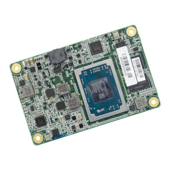
If a wrist strap is unavailable, establish and maintain contact with the system chassis throughout any procedures requiring ESD protection. Ryzen DDR4 DDR4 IT8528VG Flash BIOS BOTTOM eMMC DDR4 DDR4 PTN3460 B110 COM Express connector A110 User's Manual | GH9A3... -
Page 10: System Memory
Data will be accessed in chunks of 64 bits from the memory channels. Carrier Board Features • LPDDR4 2400 MHz memory • 4GB / 8GB Memory Down Note: The carrier board is not included in the standard package and is typically custom- ized. User's Manual | GH9A3... - Page 11 Please also maintain the pressure described in the previous step the whole time. Board-to-board connector on carrier board User's Manual | GH9A3...
-
Page 12: I/O Connectors
GBE0_MDI1- LPC_DRQ1#/ESPI_ALERT1# GBE0_MDI1+ LPC_CLK/ESPI_CK GND (FIXED) GND (FIXED) GBE0_MDI0- PWRBTN# GBE0_MDI0+ SMB_CK GBE0_CTREF SMB_DAT SUS_S3# SMB_ALERT# SATA0_TX+ SATA1_TX+ SATA0_TX- SATA1_TX- SUS_S4# SUS_STAT#/ESPI_RESET# SATA0_RX+ SATA1_RX+ SATA0_RX- SATA1_RX- GND (FIXED) GND (FIXED) USB_SSRX0- USB_SSTX0- USB_SSRX0+ USB_SSTX0+ SUS_S5# PWR_OK User's Manual | GH9A3... - Page 13 PCIE_RX2- A105 VCC_12V B105 VCC_12V GPI1 GPO3 A106 VCC_12V B106 VCC_12V PCIE_TX1+ PCIE_RX1+ A107 VCC_12V B107 VCC_12V PCIE_TX1- PCIE_RX1- A108 VCC_12V B108 VCC_12V WAKE0# A109 VCC_12V B109 VCC_12V GPI2 WAKE1# A110 GND (FIXED) B110 GND (FIXED) User's Manual | GH9A3...
-
Page 14: Signal Descriptions
Gigabit Ethernet Controller 0 1000 Mbit / sec link indicator, active LINK1000# 150Ω to 3.3VSB low. GBE0_SDP 3.3V Suspend/3.3V Gigabit Ethernet Controller 0 Software-Definable Pin. Can also be used for IEEE1588 support such as a 1pps signal. User's Manual | GH9A3... -
Page 15: Sata Signals Descriptions
PCI Express Differential Transmit Pairs 2 PCIE_TX2- AC Coupling capaci- PCIE_RX2+ I PCIE AC coupled off Device - Connect AC Coupling cap 0.1uF PCI Express Differential Receive Pairs 2 Module Slot - Connect to PCIE Conn pin PCIE_RX2- User's Manual | GH9A3... -
Page 16: Ddi Signals Descriptions
(S/W IC between AUX+ Rpu/PCH) I/O OD 3.3V / 3.3V PU 2.2K to 3.3V, PD Connect to HDMI/DVI I2C CTRLCLK HDMI/DVI I2C CTRLCLK if DDI1_DDC_AUX_SEL is pulled high CMOS 100K to GND (S/W IC between Rpu/Rpd resistor) User's Manual | GH9A3... -
Page 17: Usb Signals Descriptions
USB over-current sense, USB channels 0 and 1. A pull-up for this line shall be present on the Module. An open drain driver from a USB current monitor on the Carrier Board may drive this line low. Do not pull this line high on the Carrier Board. User's Manual | GH9A3... -
Page 18: Lvds Signals Descriptions
Connect to LVDS connector LVDS_A3- LVDS_A_CK+ O LVDS LVDS Connect to LVDS connector LVDS Channel A differential clock LVDS_A_CK- LVDS_VDD_EN A77 O CMOS 3.3V / 3.3V Connect to enable control of LVDS panel power circuit LVDS panel power enable User's Manual | GH9A3... -
Page 19: Lpc Signals Descriptions
LPC Mode: LPC clock output - 33MHz nominal ESPI_CK ESPI: 1.8V Suspend ESPI Mode: eSPI Master Clock Output / 1.8V ESPI_EN# I CMOS This signal is used by he Carrier to indicate the operating mode of the LPC/eSPI bus. User's Manual | GH9A3... -
Page 20: Spi Signals Descriptions
TPM_PP I CMOS 3.3V / 3.3V Trusted Platform Module (TPM) Physical Presence pin. Active high. TPM chip has an internal pull down. This signal is used to indicate Physical Presence to the TPM. (NC for WL9A3) User's Manual | GH9A3... -
Page 21: Power And System Management Signals Descriptions
System Management Bus bidirectional data line. CMOS SMB_ALERT# B15 I CMOS 3.3V Suspend/3.3V PU 10K to 3.3VSB System Management Bus Alert – active low input can be used to generate an SMI# (System Management Interrupt) or to wake the system. User's Manual | GH9A3... -
Page 22: Power And Gnd Signal Descriptions
Ground - DC power and signal and AC signal return path. A70, A80, A90, A100, A110, B1, B11, B21 ,B31, B41, B51, B60, B70, All available GND connector pins shall be used and tied to Carrier B80, B90, B100, B110 Board GND plane. User's Manual | GH9A3... -
Page 23: Chapter 3 - Bios Settings
When “X” appears on the left of a particular field, it indicates that a submenu which contains additional options are available for that field. To display the submenu, move the highlight to that field and press <Enter>. User's Manual | GH9A3... -
Page 24: Main
The time format is <hour>, <minute>, <second>. The time is based on the 24-hour military-time clock. For example, 1 p.m. is 13:00:00. Hour displays hours from 00 to 23. Minute displays min- utes from 00 to 59. Second displays seconds from 00 to 59. User's Manual | GH9A3... -
Page 25: Amd Chipset Setting
The system automatically powers on after power failure. Always Off The system enters soft-off state after power failure. Power-on signal input is required to power up the system. Last State The system returns to the last state right before power failure. User's Manual | GH9A3... -
Page 26: Amd Platform Setting
Enable or disable the SATA controller, or select Auto for auto-detection. Select which graphics controller will be the primary video adaptor — Int Graphics (IGD) or Ext Graphics (PEG). The information of the SATA devices installed on the system is shown. User's Manual | GH9A3... -
Page 27: Acpi Configuration
When Enabled, the system will automatically power up at a designated time every day. Once it’s switched to [Enabled], please set up the time of day — hour, minute, and second — for the system to wake up. User's Manual | GH9A3... -
Page 28: Serial Port Console Redirection
Select data bits: 7 bits or 8 bits. Parity Select parity bits: None, Even, Odd, Mark or Space. Stop Bits Select stop bits: 1 bit or 2 bits. Flow Control Select flow control type: None or Hardware RTS/CTS. User's Manual | GH9A3... -
Page 29: Trusted Computing
Select the color depth of the LCD Panel — 18 Bit, 24 Bit, 36 Bit, 48 Bit. Note: The configuration must match the specifications of your LCD Panel in order for the LCD Panel to display properly. User's Manual | GH9A3... -
Page 30: It8528 Super Io Configuration
Version 2.20.1274. Copyright (C) 2021 American Megatrends, Inc. Version 2.20.1274. Copyright (C) 2021 American Megatrends, Inc. The Super IO Chip information is displayed. Select a submenu for more settings. Serial Port Enable or disable the current serial COM port. User's Manual | GH9A3... -
Page 31: Cpu Configuration
Enable or disable the protection function that keeps no-execute codes from being executed by the CPU. XHCI Hand-off SVM Mode Enable or disable XHCI Hand-off. Enable or disable Secure Virtual Machine (SVM) for CPU virtualization. USB Mass Storage Driver Support Enable or disable USB Mass Storage Driver Support. User's Manual | GH9A3... -
Page 32: Network Stack Configuration
Set the wait time in seconds to press ESC key to abort the PXE boot. Use either +/- or numeric keys to set the value. Media detect count Set the number of times the presence of media will be checked. Use either +/- or numeric keys to set the value. User's Manual | GH9A3... -
Page 33: Csm Configuration
This field controls the execution of UEFI and Legacy Storage OpROM. Video This field controls the execution of UEFI and Legacy Video OpROM. Other PCI devices This field determines OpROM execution policy for devices other than Network, Storage or Video. User's Manual | GH9A3... -
Page 34: Watchdog Configuration
Enable or disable WatchDog function. Once it is enabled, please configure the following field. Output Options Switch output options among Mode1(System Reset) / Mode2(Output Only) / Mode3(Generate NMI) Enable Delay Set up the Enable Delay duration. Enable Delay Set up the Timeout Delay duration. User's Manual | GH9A3... -
Page 35: Security
Secure Boot. Press Enter and a prompt will show up for you to confirm. Reset To Setup Mode Clear the database from the NVRAM, including all the keys and signatures installed in the Key Management menu. Press Enter and a prompt will show up for you to confirm. User's Manual | GH9A3... - Page 36 Export the Secure Boot settings (i.e. all keys and signatures) as files to the root directory of a file system device. Press Enter and select a storage device listed in the pop-up menu. The saved files will be named automatically according to the type of key/signature as listed below. User's Manual | GH9A3...
-
Page 37: Boot
If “Boot option filter” of “CSM Configuration” is set to “UEFI and Legacy” or “UEFI only”, and “Quiet Boot” is set to enabled, “BGRT Logo” will show up for configura- tion. Refer to the Advanced > CSM Configuration submenu for more information. User's Manual | GH9A3... -
Page 38: Updating The Bios
When the BIOS IC needs to be replaced, you have to populate it properly onto the system board after the EEPROM programmer has been burned and follow the technical person's instructions to confirm that the MAC address should be burned or not. User's Manual | GH9A3... -
Page 39: Chapter 4 - Supported Software
3. After completing installation, click “Restart Now” to exit Note: setup. This step can be ignored if the applications are standalone files. Restarting the system will al- low the new software installa- tion to take effect. User's Manual | GH9A3... -
Page 40: Intel Lan Driver
5. The step displays the installing status in the progress. 2. Click “I accept the terms in the license agreement” then click “Next”. 6. After completing installation, click “Finish”. 3. Select the program features you want installed then click “Next”. User's Manual | GH9A3... -
Page 41: Audio Drivers
2. Click “Yes, I want to restart my computer now” then click “Fin- ish”. Restarting the system will al- 2. Click “Install” to begin installa- low the new software installa- tion. tion to take effect. User's Manual | GH9A3... - Page 42 Chapter 4 SUPPORTED SOFTWARE 3. Setup is now installing the driver. 4. Click “Finish” to exit installa- tion. User's Manual | GH9A3...
Need help?
Do you have a question about the GH9A3 and is the answer not in the manual?
Questions and answers