Table of Contents
Advertisement
Quick Links
Advertisement
Table of Contents

Related Manuals for DFI G4S306-C


Summary of Contents for DFI G4S306-C
-
Page 1: System Board
G4S306-C Rev. A+ System Board User’s Manual 935-G4S306-500G A80210545... -
Page 2: Features And Specifications
Introduction Chapter 1 - Introduction 1.1 Features and Specifications 1.1.1 Features Chipset • Intel 865G chipset ® ® Intel 865G Graphics Memory Controller Hub (GMCH) ® Intel 82801EB I/O Controller Hub (ICH5) Processor The system board is equipped with Socket 478 for installing one of the following supported processors. - Page 3 Introduction 64 Mbit 128 Mbit 256 Mbit 512 Mbit Density Density Width SS/DS SS/DS SS/DS SS/DS SS/DS SS/DS SS/DS Single/Double SS/DS 184-pin DDR 64/128MB 32MB/NA 128/256MB 64MB/NA 256/512MB 128MB/NA 512/1024MB 256MB/NA Expansion Slots • 1 AGP slot • 3 PCI slots AGP (Accelerated Graphics Port) •...
-
Page 4: Hardware Installation
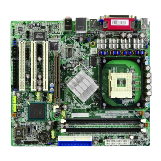
Hardware Installation Chapter 2 - Hardware Installation 2.1 System Board Layout 2nd fan PS/2 Power (JP4) DIMM LED KB/Mouse CPU fan COM 1 power +12V power IDE 2 IDE 1 USB 1-2 USB 1-4 Power Intel (JP5) 82865G LAN, USB 3-4 Line-out/Line-in/Mic-in DDR 1 DDR 2... -
Page 5: Serial Ports
Hardware Installation 2.5.2 Serial Ports " COM 1 " COM 2 The serial ports are RS-232C asynchronous communication ports with 16C550A-compatible UARTs that can be used with modems, serial printers, remote display terminals, and other serial devices. The system board is equipped with an onboard serial port (CN4 - Teal/Turquoise) for COM 1 and a 9-pin connector at location J6 for COM 2. - Page 6 Hardware Installation 2.6.3 S/PDIF Connector SPDIF out SPDIF in " The system board is equipped with a S/PDIF connector. One card- edge bracket, mounted with S/PDIF ports, will be provided as an option. Install the card-edge bracket to the system chassis then connect the audio cable connector to J3.
-
Page 7: Front Panel Connectors
Hardware Installation 2.6.13 Front Panel Connectors PWR-LED HD-LED RESET ATX-SW SPEAKER 2 1 2 2 HD-LED: Primary/Secondary IDE LED This LED will light when the hard drive is being accessed. RESET: Reset Switch This switch allows you to reboot without having to power off the system thus prolonging the life of the power supply or system. - Page 8 Hardware Installation PWR-LED: Power/Standby LED When the system’s power is on, this LED will light. When the system is in the S1 (POS - Power On Suspend) or S3 (STR - Suspend To RAM) state, it will blink every second. Note: If a system did not boot-up and the Power/Standby LED did not light after it was powered-on, it may indicate that the CPU...
Need help?
Do you have a question about the G4S306-C and is the answer not in the manual?
Questions and answers