
Related Manuals for Samson 2333 series


Summary of Contents for Samson 2333 series
- Page 1 Self-operated Pressure Regulators Type 2333 Pressure Reducing Valve with pilot valve Type 2333 Pressure Reducing Valve Mounting and Operating Instructions EB 2552-1 EN Edition November 2014...
- Page 2 Definition of signal words DANGER! NOTICE Hazardous situations which, if not Property damage message or mal- avoided, will result in death or seri- function ous injury Note: WARNING! Additional information Hazardous situations which, if not avoided, could result in death or se- Tip: rious injury Recommended action...
-
Page 3: Table Of Contents
Contents General safety instructions ................4 Process medium and scope of application ............5 Transportation and storage ................5 Design and principle of operation ..............6 Installation ....................9 Notes on installation ..................9 Strainers .....................10 Shut-off valve ....................10 Pressure gauges ...................10 Operation ....................11 Start-up .......................11 Steam applications ..................11 Set point adjustment ..................11 Decommissioning ..................12... -
Page 4: General Safety Instructions
General safety instructions General safety instructions − The regulator must be mounted, started up or serviced by fully trained and qualified personnel only; the accepted industry codes and practices are to be observed. Make sure employees or third persons are not exposed to any danger. -
Page 5: Process Medium And Scope Of Application
Process medium and scope of application Process medium and scope of application Pressure regulators for set points from 2 to 28 bar · Valve nominal sizes DN 125 to 400 · Nom- inal pressure PN 16 to 40 · Suitable for liquids, gases and vapors up to 350 °C The differential pressure across the regulator is used as auxiliary energy to operate the valve. -
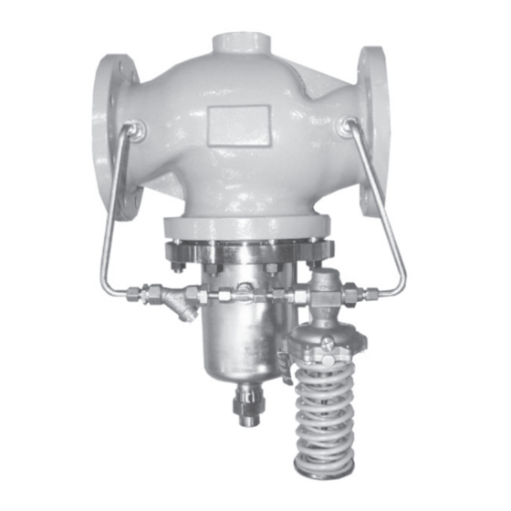
Page 6: Design And Principle Of Operation
Design and principle of operation Design and principle of op- Together with the pilot valve, the fixed restric- tion (8) or the Venturi nozzle (6) create the eration control pressure p See Fig. 1 and Fig. 2. If the downstream pressure p falls again be- The medium flows through the globe valve (1) low the set point, the pilot valve opens. - Page 7 Design and principle of operation Type 2333 Pressure Reducing Valve · Type 2422 Valve, balanced by a bellows · DN 125 to 250 Type 2422 as main valve balanced by a bellows Lower section Pilot valve with bellows Version suitable for steam Lower section Pilot valve with bellows Version suitable for liquids and gases Globe valve (main valve)
- Page 8 Design and principle of operation Type 2333 Pressure Reducing Valve · Type 2422 Valve, balanced by a diaphragm · DN 125 to 400 Pilot valve Diaphragm section Type 2422 as main valve, balanced by a diaphragm Valve body (main valve) Control pressure Valve seat Upstream pressure Plug with plug stem Downstream pressure 3.1 Positioning spring...
-
Page 9: Installation
cess especially in applications with gases, air Valve balanced by a bellows or steam. − Bellows including housing Contact SAMSON to obtain the TV-SK 17041 suspended downward documentation which contains more details on Valve balanced by a diaphragm installation requirements. -
Page 10: Strainers
4.2 Strainers 4.4 Pressure gauges Install the strainer (e.g. SAMSON Type 1/ Install a pressure gauge both upstream and Type 2) upstream of the pressure reducing downstream of the regulator to monitor the valve. -
Page 11: Operation
− Air and condensate must be allowed to 5.1 Start-up escape from the plant. Install steam trap (e.g. SAMSON Type 13 E) or air vent for First start up the regulator after mounting all steam-operated systems (e.g. SAMSON parts (e.g. valve and control line). Open con- Type 3) at a suitable location. -
Page 12: Decommissioning
Operation NOTICE Incorrectly adjusted set point or set point cannot be adjusted. Malfunction! Start by turning the set point adjust- er by one turn at a time and wait until the downstream pressure reaches the set point. As soon as the pressure re- ducing valve starts to work, you can adjust the set point by making larg- er changes. -
Page 13: Maintenance
(pi- lot valve). As in many cases, special tools are required, we advise you to contact SAMSON after-sales service to find out how to proceed to repair the regulator or replace a component (see section 10). - Page 14 Otherwise, return regulator to is closed, the pilot valve has Downstream SAMSON for repair. caused the malfunction. pressure is much higher than the Remove valve from the pipeline adjusted set point and clean seat and plug.
- Page 15 Maintenance Troubleshooting (continued) Malfunction Possible reasons Recommended action Comments Strainer in the line in which the pilot valve is installed is Clean strainer. clogged up The required minimum differ- Raise upstream pressure or re- ential pressure to operate the duce downstream pressure regulator is not available Set point range of the pilot Convert or replace pilot valve.
- Page 16 If this is the case, send a sketch of plant at the location where the process especially in applica- the plant to SAMSON for a thor- regulator is installed are not tions with gases, air or steam. ough analysis.
-
Page 17: Nameplate
Nameplate Nameplate Nameplate of main valve DIN version ANSI version Valve For ANSI version Valve type Valve size Model number Perm. differential pressure in psi Model number index Perm. temperature in °F Order number or date Body material coefficient coefficient (K x 1.17) Nominal size ANSI Class (pressure rating) -
Page 18: Technical Data
Technical data Technical data Table 3: Technical data · All pressures in bar (gauge) Type 2422 Valve Balanced by a bellows Suitable for liquids, gases or vapors · · Nominal size DN 125 DN 150 DN 200 DN 250 Nominal pressure PN 16 to 40 coefficient I (with flow divider St I) III (with flow divider St III) value... - Page 19 Technical data Type 2422 Valve · Balanced by a diaphragm· Suitable for liquids and gases Nominal size DN 125 DN 150 DN 200 DN 250 DN 300 DN 400 Nominal pressure PN 16 to 40 coefficient 1250 2000 value 0.35 0.35 Minimum differential pressure 0.8 bar 0.8 bar 0.4 bar 0.4 bar 0.5 bar 0.3 bar Δp...
-
Page 20: Dimensions
Dimensions Dimensions Type 2422 Valve · DN 125 to 250 · Balanced by a bellows DN 125 DN 150 DN 200 DN 250 Nominal size Length L 400 mm 480 mm 600 mm 730 mm Height H 285 mm 315 mm 390 mm 390 mm Height H1 460 mm 590 mm 730 mm 730 mm Height H2 145 mm 175 mm 235 mm... - Page 21 Dimensions Type 2422 Valve · DN 125 to 400 · Balanced by a diaphragm Nominal size DN 125 DN 150 DN 200 DN 250 DN 300 DN 400 Length L 400 mm 480 mm 600 mm 730 mm 850 mm 110 mm Height H1 285 mm 310 mm 380 mm 380 mm 510 mm 610 mm Height H2 145 mm 175 mm 260 mm...
-
Page 22: Customer Service
The addresses of SAMSON AG, its subsidiaries, representatives and service facilities world- wide can be found on the SAMSON website, in all SAMSON product catalogs or on the back of these Mounting and Operating Instructions. Please send your inquiries to: service@samson.de To assist diagnosis, specify the following details (see section 7): −... - Page 24 SAMSON AG · MESS- UND REGELTECHNIK Weismüllerstraße 3 · 60314 Frankfurt am Main, Germany Phone: +49 69 4009-0 · Fax: +49 69 4009-1507 EB 2552-1 EN samson@samson.de · www.samson.de...
- Page 25 Conversion from chromate coating to iridescent passivation We at SAMSON are converting the surface treatment of passivated steel parts in our production. As a result, you may receive a device assembled from parts that have be- en subjected to different surface treatment methods. This means that the surfaces of so- me parts show different reflections.
Need help?
Do you have a question about the 2333 series and is the answer not in the manual?
Questions and answers