
Related Manuals for Benning MM 10-PV


Summary of Contents for Benning MM 10-PV
- Page 1 Bedienungsanleitung Operating manual Notice d‘emploi Gebruiksaanwijzing VoltSense mV Ω Volt Sense TRUE RMS 600V CAT IV 1000V CAT III FUSED...
- Page 2 Bedienungsanleitung Operating manual Notice d‘emploi Gebruiksaanwijzing Mehrsprachige Anleitung unter www.benning.de Multilingual manuals at VoltSense mV Ω Volt Sense TRUE RMS 600V CAT IV 1000V CAT III FUSED...
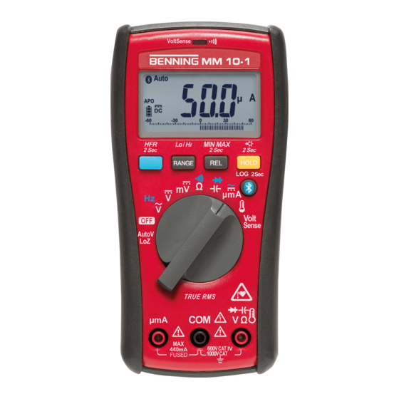
- Page 3 µmA Volt Sense AutoV TRUE RMS µmA 600V CAT IV 1000V CAT III FUSED Bild 1: Gerätefrontseite Fig. 1: Device front Fig. 1: Panneau avant de l‘appareil Fig. 1: Voorzijde van het apparaat BENNING MM 10–PV/ MM 10–1 03/ 2020...
- Page 4 Alternating voltage measurement (frequency measurement) Fig. 3 : Mesure de tension alternative (mesure de fréquence) Fig. 3: Meten van wisselspanning (frequentiemeting) VoltSense mV Ω Volt Sense TRUE RMS 600V CAT IV 1000V CAT III FUSED BENNING MM 10–PV/ MM 10–1 03/ 2020...
- Page 5 BENNING TA PV Bild 4b: AutoV/LoZ Spannungsmessung (BENNING MM 10-1) Fig. 4b: AutoV/Loz voltage measurement (BENNING MM 10-1) Fig. 4b : Mesure de tension AutoV / LoZ (BENNING MM 10-1) Fig. 4b: AutoV/LoZ spanningsmeting (BENNING MM 10-1) VoltSense mV Ω µmA...
- Page 6 Fig. 5a: Direct/ alternating current measurement (frequency measurement) (BENNING MM 10-PV) Fig. 5a : Mesure de courant continu et de courant alternatif (mesure de fréquence) (BENNING MM 10-PV) Fig. 5a: Meten van gelijk-/ wisselstroom (frequentiemeting) (BENNING MM 10-PV) VoltSense mV Ω...
- Page 7 Fig. 7: Capacity measurement/ diode testing Fig. 7 : Mesure de capacité/ contrôle de diodes Fig. 7: Capaciteitsmeting/ diodetest VoltSense mV Ω Volt Sense TRUE RMS 600V CAT IV 1000V CAT III FUSED BENNING MM 10–PV/ MM 10–1 03/ 2020...
- Page 8 Fig. 9 : Indicateur de tension avec ronfleur et LED Fig. 9: Spanningsindicator met zoemer en LED VoltSense mV Ω Volt Sense Volt Sense TRUE RMS 600V CAT IV 1000V CAT III FUSED BENNING MM 10–PV/ MM 10–1 03/ 2020...
- Page 9 Battery replacement Fig. 10 : Remplacement de la pile Fig. 10: Vervanging van de batterijen Bild 11: Sicherungswechsel Fig. 11: Fuse replacement Fig. 11: Remplacement des fusibles Fig. 11: Vervanging van de smeltzekeringen BENNING MM 10–PV/ MM 10–1 03/ 2020...
- Page 10 D F Bild 12: Aufwicklung der Sicherheitsmessleitung Fig. 12: Winding up the safety measuring leads Fig. 12: Enroulement du câble de mesure de sécurité Fig. 12: Wikkeling van veiligheidsmeetsnoeren BENNING MM 10–PV/ MM 10–1 03/ 2020...
-
Page 11: Table Of Contents
Diese Bedienungsanleitung richtet sich an Elektrofachkräfte und elektrotechnisch unterwiesene Personen Das BENNING MM 10-PV/ MM 10-1 ist zur Messung in trockener Umgebung vorgesehen. Es darf nicht in Stromkreisen mit einer höheren Nennspannung als 1000 VAC/DC eingesetzt werden (Näheres hierzu im Abschnitt 6. „Umgebungs- bedingungen). - Page 12 Dieses Symbol auf dem BENNING MM 10-PV/ MM 10-1 bedeutet, dass das BENNING MM 10-PV/ MM 10-1 konform zu den EU-Richtlinien ist. Dieses Symbol auf dem BENNING MM 10-PV/ MM 10-1 weist auf die eingebaute Sicherung hin. Dieses Symbol erscheint in der Anzeige für eine entladene Batterie.
- Page 13 1500 V DC ausschließlich den Mess adap- ter BENNING TA PV und die Schaltstellung „PV“ des BENNING MM 10-PV. Der Messadapter reduziert die am BENNING MM 10 PV anliegen- de Spannung und ist ausschließlich für das BENNING MM 10-PV zu verwenden! Elektrische Gefahr! Der Messadapter BENNING TA PV darf nur in Stromkreisen der Überspannungskategorie II mit max.
- Page 14 Ein Stück Sicherung F 440 mA, 1000 V, 10 kA, D = 10 mm, L = 34,9 mm (Art.-Nr. 10016655). Das BENNING MM 10-PV/ MM 10-1 wird durch zwei eingebaute 1,5 V Mig- non-Batterien (AA/ IEC LR06) gespeist. Die oben genannten Sicherheitsmessleitungen (geprüftes Zubehör, Art.-Nr.
- Page 15 “ in der Digitalanzeige 1 (siehe Ab- schnitt 5.2). 5.1.13 Das BENNING MM 10-PV/ MM 10-1 schaltet sich nach ca. 20 Minuten selbsttätig ab (APO, Auto-Power-Off). Es schaltet sich wieder ein, wenn der Drehschalter aus der Schaltstellung „OFF“ eingeschaltet oder eine BENNING MM 10–PV/ MM 10–1...
- Page 16 °C < 18 °C oder > 28 °C, bezogen auf den Wert bei der Referenz- temperatur von 23 °C. 5.1.16 Das BENNING MM 10-PV/ MM 10-1 wird durch zwei 1,5 V Mignon- Batterien (AA/ IEC LR6) gespeist. 5.1.17 Die Batterieanzeige 3 zeigt permanent die verbleibende Batteriekapa- zität über maximal 3 Segmente an.
- Page 17 Speicher und somit alle gespeicherten Messwerte des Datenloggers „LOG“. Die manuelle Speicherung „SAVE“ kann anschließend mehrmals gestartet und been- det werden. Die Messwerte werden fortlaufend in dem internen Speicher auf den Speicherplätzen 0001 - 4000 abgelegt. BENNING MM 10–PV/ MM 10–1 03/ 2020...
-
Page 18: Datenübertragung Zum Smartphone/ Tablet
Zur Aktivierung der Bluetooth Schnittstelle betätigen Sie die Taste Bluetooth ® ® 8 am BENNING MM 10-PV/ MM 10-1 (Symbol „ “ blinkt). Sobald eine Blue- tooth Verbindung besteht, wird das Symbol „ “ dauerhaft eingeblendet. ® Reichweite im Freigelände: ca. 10 m Umgebungsbedingungen Das BENNING MM 10-PV/ MM 10-1 ist für Messungen in trockener Umge-... - Page 19 Überlastschutz: 1000 V AC/DC Frequenzbereich: 45 Hz - 500 Hz, Sinus Eingangswiderstand: DC: 10 MΩ, AC: 10 MΩ II < 100 pF 7.2 Spannungsbereiche (PV) über Messadapter BENNING TA PV (BENNING MM 10-PV) Funktion Messbereich Auflösung Messgenauigkeit 600,0 V 0,1 V PV V DC ±...
- Page 20 30 Sekunden mit > 10 A (Pause > 10 Minuten) Überlastschutz: 11 A AC/DC Frequenzbereich: 45 Hz - 500 Hz, Sinus 7.5 Mikro-/ Milliampere-Strombereiche (µA AC/DC) (BENNING MM 10-1) Funktion Messbereich Auflösung Messgenauigkeit 600,0 µA 0,1 µA ± 1,5 % + 7 Digit...
-
Page 21: Messen Mit Dem Benning Mm 10-Pv/ Mm
AC/DC Messen mit dem BENNING MM 10-PV/ MM 10-1 8.1 Vorbereiten der Messung Benutzen und lagern Sie das BENNING MM 10-PV/ MM 10-1 nur bei den an- gegebenen Lager- und Arbeitstemperaturbedingungen, vermeiden Sie dauernde Sonneneinstrahlung. Angaben von Nennspannung und Nennstrom auf den Sicherheitsmesslei- tungen überprüfen. - Page 22 Der Messadapter reduziert die am BENNING MM 10-PV anliegende Spannung und ist ausschließlich für das BENNING MM 10-PV zu verwenden! Elektrische Gefahr! Den Messadapter BENNING TA PV in die COM-Buchse K und Buchse + L stecken. Mit dem Drehschalter 9 die gewünschte Funktion am BENNING MM 10-PV wählen.
- Page 23 Die Sicherheitsmessleitungen mit den Messpunkten kontaktieren. Un- terschreitet der Leitungswiderstand zwischen der COM-Buchse K und der Buchse L den Wert 20 Ω bis 200 Ω, ertönt im BENNING MM 10-PV/ MM 10-1 der eingebaute Summer und die rote LED O leuchtet auf.
-
Page 24: Instandhaltung
Mit dem Drehschalter 9 die gewünschte Funktion am BENNING MM 10-PV/ MM 10-1 wählen, das Symbol ““ blinkt in der Digitalanzeige 1 . Durch Betätigung der RANGE-Taste 5 die Umschaltung auf Hi (hohe Emp- findlichkeit) bzw. Lo (niedrige Empfindlichkeit) vornehmen. - Page 25 Erkennbaren Folgen von längerer Lagerung unter unzulässigen Bedingun- gen und Erkennbaren Folgen von außerordentlicher Transportbeanspruchung. In diesen Fällen ist das BENNING MM 10-PV/ MM 10-1 sofort abzuschalten, von den Messstellen zu entfernen und gegen erneute Nutzung zu sichern. 9.2 Reinigung Reinigen Sie das Gehäuse äußerlich mit einem sauberen und trockenen Tuch...
-
Page 26: Technische Daten Des Messzubehörs
Legen Sie die Batterien polrichtig in das Batteriefach, rasten Sie den Batte- riedeckel an das Unterteil an, und ziehen Sie die Schrauben an. Setzen Sie das BENNING MM 10-PV/ MM 10-1 in den Gummi-Schutzrah- men M ein. siehe Bild 11: Sicherungswechsel 9.5 Kalibrierung... -
Page 27: Umweltschutz
11. Umweltschutz Bitte führen Sie das Gerät am Ende seiner Lebensdauer den zur Verfügung ste hen den Rückgabe- und Sammelsystemen zu. BENNING MM 10–PV/ MM 10–1 03/ 2020... - Page 28 The BENNING MM 10-PV/ MM 10-1 is intended for measurements under dry am- bient conditions. It must not be used in electrical circuits with a nominal voltage higher than 1000 VAC/DC (see section 6 „Ambient conditions“).
-
Page 29: Safety Instructions
This symbol on the BENNING MM 10-PV/ MM 10-1 indicates that the BENNING MM 10-PV/ MM 10-1 is equipped with protective insulation (protection class II). Please observe the operating manual! This symbol on the BENNING MM 10-PV/ MM 10-1 means that the BENNING MM 10-PV/ MM 10-1 complies with the EU directives. -
Page 30: Scope Of Delivery
For voltage measurements on PV systems with system voltages of up to 1500 V DC, use the BENNING TA PV measuring adapter and the switch position “PV” of the BENNING MM 10-PV only. The measuring adapter reduces the voltage applied to the... -
Page 31: Device Description
The nominal measurement rate of the BENNING MM 10-PV/ MM 10-1 is 3 measurements per second (sec) for the digital display. 5.1.7 The BENNING MM 10-PV/ MM 10-1 is switched on and off by the rotat- ing switch 9 . Switch-off position “OFF”. 5.1.8... - Page 32 5.1.14 The BENNING MM 10-PV/ MM 10-1 offers individual setting possibili- ties. To change a setting, press one of the following keys and simulta- neously switch on the BENNING MM 10-PV/ MM 10-1 from the “OFF” position. BENNING MM 10–PV/ MM 10–1...
-
Page 33: Data Logger Functions
8 and simultaneously switch ® on the BENNING MM 10-PV via the rotary switch 9 . The current setting is shown by a symbol on the digital display 1 . As soon as the symbol appears, press the Bluetooth key 8 repeatedly to select from the following functions: ®... -
Page 34: Automatic Storage (Log)
“LOG”. The manual storage “SAVE” can then be started and stopped several times. The measured values are continuously stored in the internal memory at the storage locations 0001 to 4000. BENNING MM 10–PV/ MM 10–1 03/ 2020... -
Page 35: Data Transmission To The Smartphone/ Tablet
® face for real-time wireless transmission of measured values to an Android or IOS device. The “BENNING MM-CM Link” app required for this is available in the Google Play Store and in the Apple App Store. Google Playstore App Store The “BENNING MM-CM Link”... - Page 36 AC/DC Frequency range: 45 Hz - 500 Hz (sine) Input resistance: DC: 10 MΩ, AC: 10 MΩ II < 100 pF 7.2 Voltage ranges (PV) via BENNING TA PV measuring adapter (BENNING MM 10-PV) Function Measuring range Resolution Measurement accuracy 600.0 V...
- Page 37 7.4 Current ranges (A ) (BENNING MM 10-PV) AC/DC Function Measuring range Resolution Measurement accuracy 6.000 A 0.001 A A AC ± 1.5 % + 5 digits 10.00 A 0.01 A 6.000 A 0.001 A A DC ± 1.0 % + 5 digits 10.00 A...
-
Page 38: Measuring With The Benning Mm 10-Pv/ Mm
The highest voltage that may be applied to the jacks COM jack K , jack + L of the BENNING MM 10-PV/ MM 10-1 against ground is 600 V CAT IV/ 1000 V CAT III. BENNING MM 10–PV/ MM 10–1... - Page 39 Alternating voltage measurement (frequency measurement) see fig. 4b: AutoV/Loz voltage measurement (BENNING MM 10-1) Note: On the digital display 1 , the AutoV/ LoZ function (BENNING MM 10-1) is shown Auto LoZ by the „ “ symbol. It automatically determines the required measuring func- tion (AC/ DC voltage) and the ideal measuring range.
- Page 40 Use the rotary switch 9 to select the required function , the function key (blue) 4 can be used to select the coupling mode (AC or DC) on BENNING MM 10-1. Connect the black safety measuring lead to the COM jack K of the BENNING MM 10-1.
-
Page 41: Maintenance
Use the rotary switch 9 to select the required function on BENNING MM 10-PV/ MM 10-1, the symbol ““ is flashing on the digital display 1 . Press the RANGE key 5 to switch over to Hi (high sensitivity) or Lo (low sensitivity). - Page 42 Electrical danger! The BENNING MM 10-PV/ MM 10-1 is supplied by means of two integrated 1.5 V batteries (AA/ IEC LR6). Battery replacement (see fig. 10) is required as soon as all segments of the battery symbol...
-
Page 43: Technical Data Of Measuring Accessories
Insert the batteries into the battery compartment observing correct polarity, place the battery compartment cover onto the bottom part and tighten the screw. Replace the BENNING MM 10-PV/ MM 10-1 in its protective rubber holster See fig. 11: Fuse replacement 9.5 Calibration Benning guarantees compliance with the technical and accuracy specifications stated in the operating manual for the first 12 months after the delivery date. -
Page 44: Environmental Note
11. Environmental note At the end of product life, dispose of the unserviceable device via ap- propriate collecting facilities provided in your community. BENNING MM 10–PV/ MM 10–1 03/ 2020... - Page 45 électriciens et aux personnes ayant reçu une formation en électrotechnique. Le BENNING MM 10-PV/ MM 10-1 est destiné aux mesures en milieu sec et ne doit pas être utilisé sur des circuits de tension nominale supérieure à 1000 VAC/ DC (voir aussi le paragraphe 6. « Conditions d’environnement »).
- Page 46 Ce symbole sur le contrôleur BENNING MM 10-PV/ MM 10-1 signifie que le BENNING MM 10-PV/ MM 10-1 est conforme aux directives de l‘UE. Ce symbole sur le BENNING MM 10-PV/ MM 10-1 indique qu’il y a des fusibles intégrés. Ce symbole apparaît sur l’affichage lorsque la pile est déchargée.
- Page 47 Pour les mesures de tension aux installations photovoltaïques avec des tensions de système jusqu’à 1500 V DC, n’utilisez que l’adaptateur de mesure BENNING TA PV et la position « PV » de l’appareil BENNING MM 10-PV/ MM 10-1. L’adaptateur de mesure réduit la tension appliquée à l’appareil BENNING MM 10-PV/ MM 10-1 et ne doit être utilisé...
- Page 48 à courant nominal de 440 mA à action instantanée (1000 V), 10 kA, D = 10 mm, L = 34,9 mm (réf. 10016655). L‘appareil BENNING MM 10-PV/ MM 10-1 est alimenté par deux piles 1,5 V du type LR06 intégrées.
- Page 49 V et A (BENNING MM 10-PV)/ µmA AC (BENNING MM 10-1) pour filtrer les impulsions à haute fréquence, par ex. sur les entraînements moteurs cadencés. Sym- bole « HFR » sur l’écran numérique (1). La fréquence limite (-3 dB) du filtre est fg = 800 Hz.
- Page 50 < 18 °C ou > 28 °C, se réfère à la valeur pour la température de réfé- rence de 23 °C. 5.1.16 Le BENNING MM 10-PV/ MM 10-1 est alimenté par deux piles 1,5 V du type LR6 intégrées. 5.1.17 Le symbole de pile 3 indique en permanence la capacité résiduelle des piles au moyen d’un maximum de 3 segments.
- Page 51 « HOLD » 7 est actionnée, la valeur mesurée actuelle est enregistrée dans la mémoire interne et le numéro d’emplacement mémoire correspondant est brièvement affiché sur l’écran numérique 1 . Pour arrêter l’enregistrement BENNING MM 10–PV/ MM 10–1 03/ 2020...
- Page 52 ® Portée sur le terrain en plein air : 10 m environ Conditions d’environnement Le BENNING MM 10-PV/ MM 10-1 est conçu pour procéder à la mesure dans des environnements secs Hauteur barométrique pour les mesures : maximum 2000 m Catégorie de surtension / catégorie d’installation de l’appareil BENNING...
- Page 53 Plages de fréquence: 45 Hz - 500 Hz, sinus Résistance d’entrée: DC: 10 MΩ, AC: 10 MΩ II < 100 pF 7.2 Plages de tension (PV) par l’adaptateur de mesure BENNING TA PV (BENNING MM 10-PV) Fonction Domaine de mesure Résolution...
- Page 54 30 secondes avec > 10 A (pause > 10 minutes) Protection de surtension: 11 A AC/DC Plages de fréquence: 45 Hz - 500 Hz, sinus 7.5 Plages de courant (µA AC/DC) (BENNING MM 10-1) Fonction Domaine de mesure Résolution Précision de mesure 600,0 µA...
- Page 55 Mesurer avec le BENNING MM 10-PV/ MM 10-1 8.1 Préparation des mesures Utilisez et stockez le BENNING MM 10-PV/ MM 10-1 uniquement dans les condi- tions spécifiées de température de travail et de stockage, évitez l’exposition pro- longée aux rayons du soleil.
- Page 56 La plus haute tension qui doit être appliquée à la douille COM K la douille + L de l‘appareil BENNING MM 10-PV/ MM 10-1 par rapport à la terre est de 600 V CAT IV/ 1000 V CAT III. 8.2.1 Mesure de tension et de fréquence (position «...
- Page 57 Avec le commutateur rotatif 9 , sélectionner la fonction souhaitée « » et sélectionnez le mode de couplage (AC ou DC) sur le BENNING MM 10-PV à l’aide de la touche de fonction (bleue) 4 . Mettez en contact le câble de mesure de sécurité noir avec la douille COM K de l’appareil BENNING MM 10-PV.
- Page 58 La fonction de l’indicateur de tension ne nécessite aucun câble de mesure (saisie sans contact d’un champ alternatif). Le capteur récepteur se trouve sur le côté face de l’appareil BENNING MM 10-PV/ MM 10-1. Au cas où une tension de phase serait localisée, un signal acoustique est émis et la LED rouge O sur le côté...
- Page 59 ! Danger d’électrocution ! Une intervention sur le BENNING MM 10-PV/ MM 10-1 ouvert et placé sous ten- sion est exclusivement réservée à des électriciens qui doivent alors prendre des mesures particulières pour prévenir les accidents.
- Page 60 Le BENNING MM 10-PV est protégé contre la surcharge par un fusible intégré (G cartouche fusible) de 11 A à action instantanée (voir fig. 11). Le BENNING MM 10-1 est protégé contre la surcharge par un fusible intégré (G cartouche fusible) de 440 mA à...
- Page 61 10. Données techniques des accessoires de mesure norme : EN 61010-031 tension nominale maximum (tension de fonctionnement) de l’adaptateur de mesure BENNING TA PV (réf. 10217846) pour les circuits d’essai et de mesure, qui ne sont pas directement connectés au secteur : 1500 VAC/ 2000 VDC ...
- Page 62 Deze gebruiksaanwijziging is bedoeld voor: Elektriciens. Elektrotechnici. De BENNING MM 10-PV/ MM 10-1 is bedoeld voor metingen in droge ruimtes en mag niet worden gebruikt in elektrische circuits met een nominale spanning hoger dan 1000 VAC/DC (zie ook pt. 6: „Gebruiksomstandigheden“).
- Page 63 Dit symbool op de BENNING MM 10-PV/ MM 10-1 betekent dat de BENNING MM 10-PV/ MM 10-1 in overeenstemming met de EU-richt- lijnen is. Dit symbool op de BENNING MM 10-PV/ MM 10-1 duidt op de inge- bouwde zekeringen. Dit symbool verschijnt in het scherm bij een te lage batterijspanning.
- Page 64 1500 V DC uitsluitend de BENNING TA PV- meetadapter en zet de BENNING MM 10-PV in de ‘PV’-stand. De meetadapter reduceert de spanning op de BENNING MM 10-PV en mag dus uitsluitend voor de BENNING MM 10-PV gebruikt worden! ...
- Page 65 (> 60 V DC / 30 V AC rms) wordt aangegeven door een extra knipperend symbool „()“. 5.1.5 Bij de BENNING MM 10-PV/ MM 10-1 weerklinkt er een signaal wanneer u op een toets drukt. Het indrukken van een verkeerde toets is te herken- nen aan een tweevoudig signaal.
- Page 66 Bij een langere druk op de toets (2 s) wordt de LOG-functie geactiveerd en verschijnt ondertussen het symbool ‘ ’ op de display 1 . Zie para- graaf 5.2 5.1.13 De BENNING MM 10-PV/ MM 10-1 schakelt na ong. 20 minuten auto- BENNING MM 10–PV/ MM 10–1 03/ 2020...
- Page 67 M . Het rubberen beschermingsframe M maakt het mogelijk om de BENNING MM 10-PV/ MM 10-1 tijdens de metingen op te stellen of met de geïnte- greerde magneet te bevestigen. 5.2 Functies van de datalogger...
- Page 68 ‘LOG’ gewist. De manuele opslagfunctie ‘SAVE’ kan aansluitend meermaals gestart en beëindigd worden. De meetwaarden worden doorlopend in het interne geheugen bewaard op geheugenplaatsen 0001 - 4000. BENNING MM 10–PV/ MM 10–1 03/ 2020...
- Page 69 Bluetooth -toets 8 op ® ® de BENNING MM 10-PV/ MM 10-1 (het symbool „ “ knippert). Zodra er een Blu- etooth verbinding is gemaakt, blijft het symbool „ “ permanent branden. ®...
- Page 70 Beveiliging tegen overbelasting: 1000 V AC/DC Frequentiebereik: 45 Hz - 500 Hz, sinus Ingangsweerstand: DC: 10 MΩ, AC: 10 MΩ II < 100 pF 7.2 Spanningsbereik (PV) met de meetadapter BENNING TA PV (BENNING MM 10-PV) Functie Meetbereik Resolutie Nauwkeurigheid...
- Page 71 7.4 Stroombereiken (A ) (BENNING MM 10-PV) AC/ DC Functie Meetbereik Resolutie Nauwkeurigheid 6,000 A 0,001 A A AC ± 1,5 % + 5 Digit 10,00 A 0,01 A 6,000 A 0,001 A A DC ± 1,0 % + 5 Digit...
- Page 72 Gevaarlijke spanning! De hoogste spanning die aan het COM-bus K bus + L van de BENNING MM 10-PV/ MM 10-1 ligt t.o.v. aarde, mag maximaal 600 V CAT IV/ 1000 V CAT III bedragen. , AutoV/LoZ) 8.2.1 Spannings-/ frequentiemeting (stand:...
- Page 73 MM 10-PV en mag dus uitsluitend voor de BENNING MM 10-PV gebruikt worden! Gevaarlijke spanning! Plaats de meetadapter BENNING TA PV in de COM- K en +-contactbus L . Kies met de draaiknop 9 de gewenste instelling op de BENNING MM 10-PV.
- Page 74 Breng de veiligheidsmeetleidingen in contact met de meetpunten. Wanneer de leidingweerstand tussen de COM- bus K en de bus L lager ligt dan het bereik 20 kΩ en 200 kΩ, zal de zoemer van de BENNING MM 10-PV/ MM 10-1. geactiveerd worden en de rode led O oplichten.
- Page 75 COM-bus K en in de bus L . Leg het contactpunt (uiteinde van de sensorkabel) aan de te meten plaats en lees de gemeten waarde af in het display 1 van de BENNING MM 10-PV/ MM 10-1.
- Page 76 Reinig de behuizing aan de buitenzijde met een schone, droge doek. (speciale reinigingsdoeken uitgezonderd). Gebruik geen oplos- en/ of schuurmiddelen om de BENNING MM 10-PV/ MM 10-1 schoon te maken. Let er in het bijzonder op dat het batterijvak en de batterijcontacten niet vervuilen door uitlopende batte- rijen.
- Page 77 Leg de batterijen in de juiste richting in het batterijvak en klik het deksel weer op de achterwand en draai de schroeven er weer in. Plaats de rubber beschermhoes M weer op de BENNING MM 10-PV/ MM 10-1. Zie fig. 11: Vervanging van de smeltzekeringen 9.5 IJking...
- Page 78 Benning Elektrotechnik & Elektronik GmbH & Co. KG Münsterstraße 135 - 137 D - 46397 Bocholt Phone: +49 (0) 2871 - 93 - 0 • Fax: +49 (0) 2871 - 93 - 429 www.benning.de • E-Mail: duspol@benning.de...
Need help?
Do you have a question about the MM 10-PV and is the answer not in the manual?
Questions and answers