Table of Contents
Advertisement
Available languages
Available languages
Bedienungsanleitung
D
Operating manual
Mehrsprachige Anleitung auf beigefügter CD und unter
AUTOTEST
MAX-MIN AVG ▲
▼
AutoPeak HOLD
MAX
MIN
AVG
%
A-SAVE SAVE LOAD CLR RATE LOG MEM
RANGE
HFR
°C/°F
AC+DC
mV
AutoV
LoZ
A
mA
COM
MAX
MAX
400 mA
10 A
FUSED
FUSED
Multilingual manuals on included CD and at
MM 12
T-POINT
dBm % HFR
µms VAFs
MkHz
AC+DC
s°F°C%
µmVAF
MkΩHz
dB
dBm
SETUP
ENTER A HOLD
CANCEL P HOLD
AC+DC
AC+DC
Hz
V Ω
600V
CAT IV
1000V
CAT III
www.benning.de
Advertisement
Table of Contents

Related Manuals for Benning MM 12


Summary of Contents for Benning MM 12
- Page 1 Bedienungsanleitung Operating manual Mehrsprachige Anleitung auf beigefügter CD und unter www.benning.de Multilingual manuals on included CD and at MM 12 AUTOTEST T-POINT MAX-MIN AVG ▲ dBm % HFR µms VAFs ▼ AutoPeak HOLD MkHz AC+DC s°F°C% µmVAF MkΩHz SETUP...
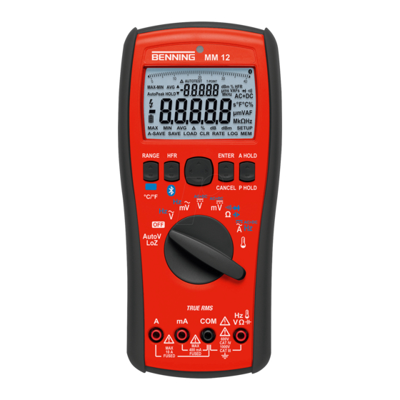
- Page 2 RANGE ENTER A HOLD CANCEL P HOLD °C/°F AC+DC AC+DC AC+DC AutoV V Ω 600V CAT IV 1000V 400 mA CAT III 10 A FUSED FUSED Bild 1: Gerätefrontseite Fig. 1: Front tester panel BENNING MM 12 07/ 2016...
-
Page 3: Ac Current Measurement
CAT IV 1000V 1000V 400 mA 400 mA CAT III CAT III 10 A 10 A FUSED FUSED FUSED FUSED Bild 4: Gleichstrommessung Bild 5: Wechselstrommessung Fig. 4: DC current measurement Fig. 5: AC current measurement BENNING MM 12 07/ 2016... - Page 4 1000V 400 mA 400 mA CAT III CAT III 10 A 10 A FUSED FUSED FUSED FUSED Bild 8: Durchgangsprüfung mit Summer Bild 9: Kapazitätsmessung Fig. 8: Continuity Testing with buzzer Fig. 9: Capacity Testing BENNING MM 12 07/ 2016...
-
Page 5: Temperature Measurement
10 A 10 A FUSED FUSED FUSED FUSED Bild 10: Frequenzmessung Bild 11: Temperaturmessung Fig. 10: Frequency measurement Fig. 11: Temperature measurement Bild 12: Batteriewechsel Bild 13: Sicherungswechsel Fig. 12: Battery replacement Fig. 13: Fuse replacement BENNING MM 12 07/ 2016... - Page 6 D Bild 14: Aufwicklung der Sicherheitsmessleitung Fig. 14: Winding up the safety measuring leads Bild 15: Aufstellung des BENNING MM 12 Fig. 15: Standing up the BENNING MM 12 BENNING MM 12 07/ 2016...
- Page 7 Elektrofachkräfte und elektrotechnisch unterwiesene Personen Das BENNING MM 12 ist zur Messung in trockener Umgebung vorgesehen. Es darf nicht in Stromkreisen mit einer höheren Nennspannung als 1000 V AC/ DC eingesetzt werden (Näheres hierzu im Abschnitt 6. „Umgebungsbedingungen“). In der Bedienungsanleitung und auf dem...
- Page 8 Zum Lieferumfang des BENNING MM 12 gehören: 3.1 ein Stück BENNING MM 12, 3.2 ein Stück Software BENNING PC-Win MM 12 3.3 ein Stück serielles Datenkabel mit USB 2.0 kompatiblen Anschluss 3.4 ein Stück Sicherheitsmessleitung, rot (L = 1,4 m), 3.5 ein Stück Sicherheitsmessleitung, schwarz (L = 1,4 m),...
- Page 9 Das BENNING MM 12 bestätigt jede Tastenbetätigung mit einem Signalton. Ungültige Tastenbetätigungen werden mit einem zweifachen Signalton bestätigt. Bei unkorrekter Beschaltung der Buchsen für den mA- M / A-Bereich N warnt das BENNING MM 12 mit einem Signalton und der Anzeige von ProbE im Display 1 .
- Page 10 < 18 °C oder > 28 °C, bezogen auf den Wert bei der Referenz temperatur von 23 °C. 5.1.10 Das BENNING MM 12 wird durch vier 1,5 V Mignon-Batterien (AA/ IEC LR6) gespeist. 5.1.11 Die Batterieanzeige 4 zeigt permanent die verbleibende Batteriekapazität über maxi- mal 3 Segmente an.
- Page 11 P2. L = 10 x log (P1/ P2). Befindet sich das BENNING MM 12 in der Funktion der Wechselspannungsmessung (V AC), wählen Sie über die Taste Cursor 7 die Menüfunktion „dB“ oder „dBm“ an und starten Sie durch Betätigung der Taste ENTER 8 (oben/▲) die Messung.
- Page 12 5.3.5 SETUP-Menü Das BENNING MM 12 verfügt über individuelle Einstellmöglichkeiten. Um eine Einstellung zu ändern, wählen Sie über die Taste Cursor 7 das Menü „SETUP“ an. Betätigen Sie die Taste ENTER 8 (oben/▲), um das Menü „SETUP“ zu öffnen. Über die Taste Cursor 7 können folgende Einstellungen vorgenommen werden:...
- Page 13 Bei Arbeitstemperatur von 41 °C bis 50 °C: relative Luftfeuchte kleiner 45 %, Lagerungstemperatur: Das BENNING MM 12 kann bei Temperaturen von - 20 °C bis + 60 °C (Luftfeuchte 0 bis 80 %) gelagert werden. Dabei ist die Batterie aus dem Gerät herauszunehmen.
- Page 14 Eingangswiderstand: < 2 Ω am mA-Eingang, < 0,1 Ω am A-Eingang Frequenzbereich: 40 Hz - 10 kHz Maximale Messzeit: 1 Minute am A-Eingang (Pause > 20 Minuten) 10 Minuten am mA-Eingang (Pause > 20 Minuten) BENNING MM 12 07/ 2016...
- Page 15 ± (1,0 % des Messwertes + 20 Digit) 7.7 Frequenzbereiche Messbereich Auflösung Messgenauigkeit 400,0 Hz 0,1 Hz 4,000 kHz 1 Hz ± 3 Digit bei 3¾-stelliger Anzeige ± 10 Digit bei 4¾-stelliger Anzeige 40,00 kHz 10 Hz 100,0 kHz 100 Hz BENNING MM 12 07/ 2016...
- Page 16 , Hz, Buchse für mA-Bereich M und der Buchse für 10 A-Bereich N des BENNING MM 12 gegenüber Erde liegen darf, beträgt 600 V CAT IV/ 1000 V CAT III. 8.2.1 Spannungsmessung Mit dem Drehschalter J die gewünschte Funktion (V AC, mV AC, V DC, mV DC) am BENNING MM 12 wählen.
- Page 17 Bild 9: Kapazitätsmessung 8.7 Frequenzmessung Mit dem Drehschalter J die gewünschte Funktion (V AC, mV AC, A AC) am BENNING MM 12 wählen. Mit der Taste Funktion 5 (unten/▼) am BENNING MM 12 die Umschaltung auf Fre quenz- BENNING MM 12...
- Page 18 Mit dem Drehschalter J die gewünschte Funktion ( ) am BENNING MM 12 wählen. Mit der Taste Funktion 5 (unten/▼) am BENNING MM 12 die Umschaltung auf °C oder °F vornehmen. Den Temperatursensor (K-Typ) mit den Buchsen COM L und K polrichtig kontaktieren.
- Page 19 Bringen Sie den Drehschalter J in die Schaltstellung „OFF“. Entfernen Sie den Gummi-Schutzrahmen O vom BENNING MM 12. Legen Sie das BENNING MM 12 auf die Frontseite und lösen Sie die untere Schraube vom Batteriedeckel. Heben Sie den Batteriedeckel vom Unterteil ab.
- Page 20 12. Umweltschutz Bitte führen Sie das Gerät am Ende seiner Lebensdauer den zur Verfügung ste- hen den Rückgabe- und Sammelsystemen zu. BENNING MM 12 07/ 2016...
-
Page 21: Table Of Contents
The BENNING MM 12 is designed for measurements in dry surroundings. It must not be used in electrical circuits with rated voltages higher than 1000 V AC/ DC (For more details, see in section 6 “Ambient conditions”). The following symbols are used in the operating manual and on the BENNING MM 12 itself: ... -
Page 22: Safety Notes
Regularly wipe the housing by means of a dry cloth and cleaning agent. Do not use any polishing agents or solvents! Scope of delivery The scope of delivery for the BENNING MM 12 comprises: 3.1 One BENNING MM 12 3.2 One software BENNING PC-Win MM 12 3.3 One serial data cable with USB 2.0 compatible connection... -
Page 23: Description Of Unit
In the event of an incorrect circuit of the jack for the mA M / A range N BENNING MM 12 warns with a signal sound and the indication of ProbE in the display 1... -
Page 24: Key Functions
BENNING MM 12 during the measuring process or to stand it upright. 5.1.16 The BENNING MM 12 has an optical interface P on the top side. This is used for the galvanic isolation of the measuring signal to a PC/ laptop. The enclosed data cable is used for the transmission of measuring data and is equipped with a USB 2.0 compa-... -
Page 25: Menu Functions
The level measurement in decibels is the logarithmic ratio of two powers P1 to P2. LP = 10 x log (P1/P2). If the BENNINGF MM 12 is in the AC voltage (V AC) measuring mode, use the Cursor key 7 to select the menu function “dB” or “dBm” and start the measurement by pres- sing the ENTER key 8 (up/ ▲). -
Page 26: Data Logger Function "Log
The measured values stored in the data logger can be read out and stored as MS Excel file by ® means of the enclosed PC software BENNING PC-Win MM 12. 5.5 Memory function “MEM” The memory function “MEM” allows the automatic and manual storage of series of measurements with up to 1,000 measured values. -
Page 27: Ambient Conditions
At operating temperatures of 41 °C to 50 °C: relative humidity under 45 %. Storage temperature: The BENNING MM 12 can be stored at temperatures from - 20 °C to + 60 °C (humidity 0 up to 80 %). The batteries must be removed from the unit. - Page 28 AC accuracy plus 1 % of the measured value, 40 Hz to 400 Hz Limiting frequency (- 3 dB): 800 Hz Attenuation: approx. - 24 dB Peak-Hold: ± 3 % of the measured value + 200 digits, 40 Hz to 1 kHz, sinusoidal BENNING MM 12 07/ 2016...
-
Page 29: Continuity Testing
10 kHz - 100 kHz 40.00 mV 10 mV 10 mV 400.0 mV 40 mV 100 mV 4.000 V 0.4 V 40.00 V 10 V 400.0 V 40 V not specified 1000 V 400 V BENNING MM 12 07/ 2016... - Page 30 Use the rotating switch J to select the required range and function (A AC, A DC, A AC/ DC) on the BENNING MM 12. Press the Function key 5 (down/ ▼) of the BENNING MM 12 to select the current type to be measured: alternating current (AC), direct current (DC) or (AC+DC).
- Page 31 ) on the BENNING MM 12. Press the Function key 5 (down/ ▼) of the BENNING MM 12 to switch over to °C or °F. Connect the temperature sensor (type K) to the COM jack L and to the jack K observing correct polarity.
- Page 32 Before opening the BENNING MM 12, ensure that it is not connected to a source of voltage! Electrical danger! Any work required on the BENNING MM 12 when it is under voltage must be done only by a qualified electrician. Special steps must be taken to prevent accidents.
- Page 33 This allows you to bring the measuring probe and the BENNING MM 12 up to the measuring point together. The support at the back of the holster O can be used to prop the BENNING MM 12 up in a diagonal position (to make reading easier) or to suspend it (see fig. 15).
- Page 34 Benning Elektrotechnik & Elektronik GmbH & Co. KG Münsterstraße 135 - 137 D - 46397 Bocholt Phone: +49 (0) 2871 - 93 - 0 • Fax: +49 (0) 2871 - 93 - 429 www.benning.de • E-Mail: duspol@benning.de...
Need help?
Do you have a question about the MM 12 and is the answer not in the manual?
Questions and answers