Table of Contents
Advertisement
EN
KLEM NTIS
INSTRUCTION M NU L
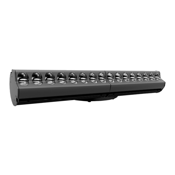
KLEMANTIS AS 1000 RGBW AL2025)
Congratulations on choosing an ADB product! We thank you for your custom.
Please note that this xture - like all the others in the wide ADB range - has been designed and made with total
quality assurance to ensure excellent performance and best meet your expectations and requirements.
www.adbstagelight.com
Advertisement
Table of Contents

Related Manuals for Osram ADB KLEMANTIS AS 1000


Summary of Contents for Osram ADB KLEMANTIS AS 1000
- Page 1 KLEM NTIS INSTRUCTION M NU L KLEMANTIS AS 1000 RGBW AL2025) Congratulations on choosing an ADB product! We thank you for your custom. Please note that this xture - like all the others in the wide ADB range - has been designed and made with total quality assurance to ensure excellent performance and best meet your expectations and requirements.
- Page 2 INDEX SAFETY INFORMATION INTRODUCTION Presentation Product overview UNPACKING Package contents Accessories INSTALLATION AND START-UP Installing the fixture 4.1.1 Introduction 4.1.2 Installation configurations 4.1.3 How to calculate positioning distance from cyclorama 4.1.4 Focus and tilt angle 4.1.5 Tips tricks Connecting to main Supply Connecting the control signal line: DMX / Art-Net Control Panel MAINTENANCE...
-
Page 3: Safety Information
1. SAFETY INFORMATION How to get a multilingual version of your SAFETY INSTRUCTIONS. You may always download multilingual safety instruction for this ADB product from: https://www.adbstagelight.com Ref: FIS01B - KLEMANTIS AS Safety Information Come ottenere le INFORMAZIONI DI SICUREZZA nella versione multilingue. - Page 4 2. INTRODUCTION Presentation The new ADB KLEMANTIS is an asymmetric cyclight based on a RGBW LED module. Its light output is enhanced with an innovative optical unit, which enables the Klemantis to generate a uniform light with excellent diffusion and perfectly blended colours.
-
Page 5: Product Overview
Product overview Risk Group 2 t t t a a ta 4 4 ta 40 0 ta 40 ° ° ta 40 °C C ta 40 °C WARNING CAUTION. Possibly hazardous optical radia- MINIMUM DISTANCE OF INFLAMMABLE 0 0 0 . . 0.2 2 0.2 m m 0.2 m tion emitted from this product. -
Page 6: Package Contents
3. UNPACKING Package contents Package contents - Fig. 3 • 1x Safety Information Leaflet FIS01B • 1x Omega Bracket 319102-801 • 1x powerCON TRUE 1 to Bare Ends Mains Cable CAB02B-801 KLEMANTIS AS 1 RGBW... -
Page 7: Optional Accessories
Optional Accessories AZ2001000200 Lenses 28° AZ2001000210 Lenses 40° Fig. 4 A - AZ2001000200 Kit Klemantis Symmetric Lenses 28° (2 sets of 0.5 meter) AZ2001000210 Kit Klemantis Symmetric Lenses 40° (2 sets of 0.5 meter) (provided in a box where both symmetrical and asymmetrical lenses can be stored) B - Hook clamp - ADB-1092.10.600 C - Safety bond - 105041/001 D - Junction pin - AA20000001020... -
Page 8: Installation And Start-Up
4. INSTALLATION AND START-UP Installing the fixture 4.1.1 Introduction The Klemantis’ unique asymmetric optical unit has been designed to respond to the increasing need to illuminate walls, scenery and cycloramas uniformly with a smooth, even wash of seamlessly blended colours. The Klemantis ensures good colour consistency and uniform light distribution on very high scenery, even when the lighting fixture and the projection surface are very close together. - Page 9 Klemantis units may be installed in a bottom, top and bottom, or top only set-up, depending on the height of the surface to be lit and on the required effect (total evenness of the light on the cyclorama or a linearly fading intensity effect). When Klemantis units are installed in a single row (top or bottom), they create a uniform horizontal light distribution which fades vertically (see Fig.
- Page 10 Safety cables must be inserted in the two anchor points and attached to the truss Installing the fixture - Fig. 7 The fixture can be installed on the floor, on a truss, on the ceiling or on a wall. WARNING: safety cables must be installed in every case except when the fixture is on the ground. (Code 2X 105041/001 available on request.) The safety cables must be fastened to the unit supporting structure and then hooked onto the fastening points found on the sides of the fixture.
- Page 11 4.1.3 How to calculate the installation distance from a cyclorama In the case of the two-row set-up, the recommended distance for the most even light on a cyclorama can be easily calculated using the following formula: d = distance from cyclorama H = height of cyclorama Klemantis Distance (D)
- Page 12 4.1.4 Focus and tilt angle The Klemantis performs best if tilted 45° When one Klemantis is installed properly in place (at the correct distance, perfectly parallel to the wall and tilted 45°), the light distribution on the cyclorama looks like a rectangular distribution with soft edges on the sides and soft vertical fading. Focus Fig.
- Page 13 Connecting to main power supply MAINS IN MAINS OUT Link additional fixtures via the Power Thru connector - Fig. 11 Up to five Klemantis AS1000s may be linked via Power Thru connectors on the same power line (16 Amp). NOTE: plug the cable into AC power 100/240V 50/60Hz on a non-dimmable circuit. Do not connect to a dimmer power line. KLEMANTIS AS 1 RGBW...
-
Page 14: Connecting The Control Signal Line: Dmx / Art-Net
Connecting the control signal line: DMX / Art-Net DMX IN DMX OUT DMX 512 5 PIN SCREEN SIGNAL SIGNAL DMX 512 Connecting the control signal line: DMX / Art-Net - Fig. 12-13 Use a cable conforming to specifications EIA RS-485: 2-pole twisted, shielded, 120 characteristic impedance, 22-24 AWG, low capacity. Do not use microphone cable or other cable with characteristics differing from those specified. -
Page 15: Control Panel
Control panel Switching the fixture on - Fig. 14 The fixture comes on immediately when the power cord is plugged in. Menu settings status If no button is pressed, the display automatically returns to idle status after a time-out interval of about 60 seconds. Any modified value that has not yet been confirmed with the key will be cancelled. -
Page 16: Maintenance
5. MAINTENANCE Replacing fuses 2 Fusibili 6.3 x 32 mm 4AT (p/n FUS00B) Replacing fuses - Fig. 16 Each fixture has two fuses on the main power cord connection. KLEMANTIS AS 1 RGBW... -
Page 17: Routine Cleaning
Routine cleaning Parts requiring frequent cleaning. Routine cleaning - Fig. 17 To ensure optimal operation and performance for a long time it is essential to clean the parts subject to dust and grease deposits periodically. The frequency with which the following operations need to be carried out depends on various factors such as wear and the working environment (air humidity, dust, salinity, etc.). - Page 18 • Ambient temp. (min-max): -20°C / +40° C • Maximum surface temperature: 90° POWER CONNECTION OPTICAL SPECS • Power input: Neutrik PowerCON TRUE 1 • Source: Osram RGBW LED • Power thru: Neutrik PowerCON TRUE 1 • Lifetime L : 57,000 h DATA CONNECTION APPROVALS •...
- Page 19 7. APPENDIX Klemantis installation steps The following steps summarize the recommended procedure for installing a single row of units (for instance on the floor): 1. Calculate the proper installation distance (D) from the cyclorama. 2. Place the Klemantis stably and make sure all Klemantis units are parallel to the cyclorama, at the set distance (D). Reduce the gap between two adjacent fixtures to a minimum (1 - 2 mm).
- Page 20 b. Loosen the tilting knobs so that the Klemantis units may be tilted (fig. 20). c. Place your smartphone in the middle of the Klemantis housing as shown in the picture (fig. 21), so that the plastic bulges on the top surface between the lenses define the slope of your smartphone.
- Page 21 5. Turn on the bottom row of Klemantis units to illuminate the cyclorama. Observe the cyclorama from where the audience would, and single out any light peaks or gaps: these might occur at a specific Klemantis unit. 6. For each Klemantis unit identified, an observer should stand in front of the cyclorama while another person tilts the Klemantis slightly (without a digital level) to adjust its tilt finely based on feedback from the observer.
- Page 22 KLEMANTIS AS 1 RGBW...
- Page 23 KLEMANTIS AS 1 RGBW...
- Page 24 I - 24068 Seriate (BG) - via Pastrengo, 3/b Phone +39 035 654311 - www.adbstagelight.com...
Need help?
Do you have a question about the ADB KLEMANTIS AS 1000 and is the answer not in the manual?
Questions and answers