Rice Lake 920i Installation Manual
Programmable hmi indicator/controller panel mount enclosure installation
Hide thumbs
Also See for 920i:
- Installation manual ,
- Programming reference manual (98 pages) ,
- Technical manual (40 pages)
Advertisement
920i
Programmable HMI Indicator/Controller
®
Panel Mount Enclosure Installation
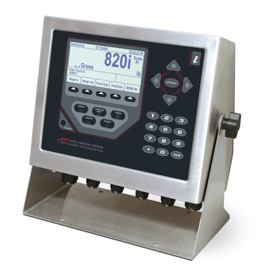
This document contains drawings, replacement parts lists and instructions for installing panel mount models of 920i indicators.
See the 920i Installation Manual, PN 67887, for general installation, configuration and calibration information.
The 920i has no on/off switch. Before opening the unit, ensure the power cord is disconnected from the power
WARNING
outlet.
Use a wrist strap for grounding and to protect components from electrostatic discharge (ESD) when working
inside the indicator enclosure.
This unit uses double pole/neutral fusing which could create an electric shock hazard. Procedures requiring
work inside the indicator must be performed by qualified service personnel only.
9.16"
8.02"
April 20, 2018
11.56"
10.51"
Illustration is not to scale, dimensions
are for reference only.
Figure 1. Panel Cutout for Panel Mount Enclosure
Outer Perimeter of
Exterior Faceplate
(Solid Line)
Panel Cutout
(Dashed Line)
Interior Housing
(Dotted Line)
PN 69988 Rev B
Advertisement
Table of Contents

Related Manuals for Rice Lake 920i


Summary of Contents for Rice Lake 920i
- Page 1 This document contains drawings, replacement parts lists and instructions for installing panel mount models of 920i indicators. See the 920i Installation Manual, PN 67887, for general installation, configuration and calibration information. The 920i has no on/off switch. Before opening the unit, ensure the power cord is disconnected from the power WARNING outlet.
- Page 2 5. Use the nine 1 1/2" screws (PN 82425) to secure the clinching bracket to the panel door. Reinforcing Plate 1 1/2" screws (PN 82425) Clinching Bracket 1/4" screws (PN 71522) Figure 3. Clinching Bracket Assembly © Rice Lake Weighing Systems ● All Rights Reserved...
- Page 3 920i Programmable HMI Indicator/Controller Panel Mount Enclosure Panel is located between the front bezel and the reinforcing plate (not shown). The clinch bracket draws the front bezel against the panel Clinch Bracket when screws are tightened. Figure 4. Panel Mount Enclosure Grounding Except for the power cord, all cables routed through the cord grips should be grounded against the indicator enclosure.
- Page 4 (15 mm) of the insulation to expose the braid where the cable passes through the clamp. Load Cell Cables Cut the shield wire just past the grounding clamp. Shield wire function is provided by contact between the cable shield and the grounding clamp. © Rice Lake Weighing Systems ● All Rights Reserved...
- Page 5 Wickmann Time-Lag 19372 Series UL Recognized, Semko and VDE Approved See the 920i installation manual for additional specifications. Parts Kit Contents Table 1-1 lists the parts kit contents for the panel mount version of the 920i. Part No. Description 14626...
- Page 6 Specifications subject to change without notice. Rice Lake Weighing Systems is an ISO 9001 registered company. 230 W. Coleman St. • Rice Lake, WI 54868 • USA U.S. 800-472-6703 • Canada/Mexico 800-321-6703 • International 715-234-9171 • Europe +31 (0)26 472 1319...
Need help?
Do you have a question about the 920i and is the answer not in the manual?
Questions and answers