Rice Lake 920i Installation Manual
Programmable hmi indicator/controller
Hide thumbs
Also See for 920i:
- Installation manual ,
- Programming reference manual (98 pages) ,
- Technical manual (40 pages)

Related Manuals for Rice Lake 920i


Summary of Contents for Rice Lake 920i
- Page 1 ® Programmable HMI Indicator/Controller Version 4.01 Installation Manual Rev H Board Requires Minimum Version 3.14 67887...
-
Page 3: Table Of Contents
Course descriptions and dates can be viewed at www.ricelake.com or obtained by calling 715-234-9171 and asking for the training department. © June 2011 Rice Lake Weighing Systems. All rights reserved. Printed in the United States of America. Specifications subject to change without notice. - Page 4 Symbol Widgets ..............103 Rice Lake continually offers web-based video training on a growing selection of product-related topics at no cost.
- Page 5 10.14 Specifications ............. . . 127 920i Limited Warranty ......................... 128...
- Page 6 920i Installation Manual...
-
Page 7: About This Manual
3; If using in conjunction with iQUBE , use version Rice Lake Weighing Systems distributor 4.x and iRev 4. site at www.ricelake.com/manuals. Configuration and calibration of the indicator can be... -
Page 8: Operating Modes
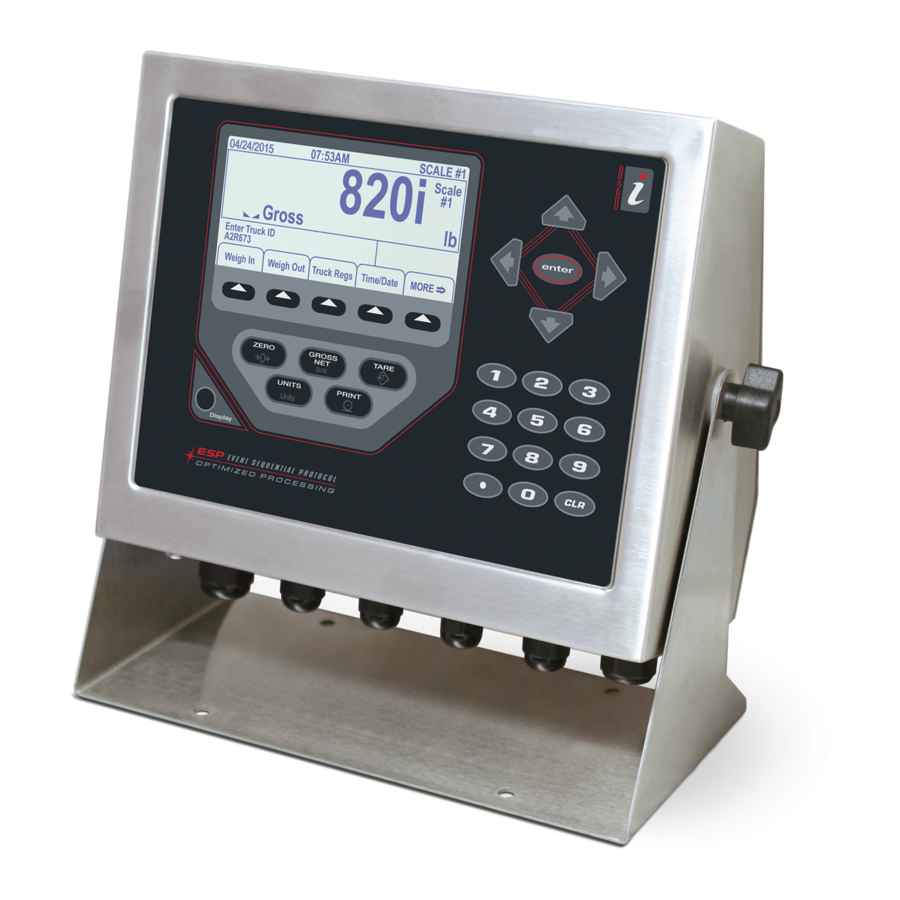
UNITS PRINT • Pulse input card for use with pulse count and pulse rate setpoints. Figure 1-1. 920i Front Panel • Dual-channel analog input card supports 0–10 VDC, 0–20 mA, ambient temperature, and four Enclosures types of thermocouple. -
Page 9: Indicator Operations
Indicator Operations softkey can be configured to Display Accum display the current accumulator value. Printing while Basic 920i operations are summarized below: the accumulator is displayed, or when the setpoint Toggle Gross/Net Mode PSHACCUM function is active, uses the ACCFMT print format (see Section 6.0 on page 62). -
Page 10: Contrast Adjustment
Panel mount model, 230 VAC, North American, NEMA 15-5 power cord 69766 69777 Panel mount model, 230 VAC, European, CEE 7/7 power cord 72137 72138 Wall mount model, 115 VAC 69763 69770 Table 1-3. Part Numbers for 920i Models 920i Installation Manual... -
Page 11: Summary Of Changes
Dual-channel analog output card 103138 ribbon cable and power supply cable. Dual serial port expansion card 67604 Table 1-5. Part Numbers for 920i Expansion Boards 24-channel digital I/O expansion card 67601 Relay Options 1MB NV RAM memory expansion card 67600... - Page 12 • There is no SDRAM module on the back side to a PC prior to powering the 920i down. as the memory is now on the main board. • Removed the EXIT key during Setup mode.
-
Page 13: Hardware And Software Compatibility
• New IMAGE parameter on the FEATURE menu allows inversion of the display image Because select components of the 920i CPU have (blue-on-white or white-on-blue) for support of recently become obsolete, certain design changes have the outdoor display option. See Section 3.2.3. -
Page 14: Installation
Ensure indicator, this manual, and a parts kit. If any parts silver (conductive) side of foil is turned were damaged in shipment, notify Rice Lake outward for contact with the grounding Weighing Systems and the shipper immediately. -
Page 15: Load Cells
• For load cell cables, cut the shield wire just When connections are complete, reinstall load cell past the grounding clamp. Shield wire connector on the A/D card and use two cable ties to function is provided by contact between the secure the load cell cable to the inside of the cable shield and the grounding clamp. -
Page 16: Serial Communications
2.3.3 Serial Communications The four communications ports on the 920i DIN-8 Connector for board support full duplex RS-232, 20 mA output, or PS/2 Remote Keyboard RS-485 communications at up to 115200 bps. To attach serial communications cables, route the cable through the cord grip and ground the shield wire as described in Section 2.3.1 on page 8. - Page 17 SLOT 2 SLOT 1 POWER EXPANSION BUS SUPPLY +6VDC PIEZO BUZZER OPTION OPTION CARD LOCATIONS INTERFACE REMOTE SETUP BOARD PORT 2 SWITCH CONNECTION BOOT PORT 3 PORT 4 DIGITAL I/O MODE PORT 1 Figure 2-5. 920i Rev G CPU Board Installation...
-
Page 18: Digital I/O
Figure 2-6. 920i Rev H CPU Board 2.3.4 Digital I/O Digital inputs can be set to provide many indicator functions, including all keypad functions. Digital J2 Pin J2 Signal inputs are active low (0 VDC), inactive high (5 VDC). +5 VDC Digital outputs are typically used to control relays that drive other equipment. -
Page 19: Installing Option Cards
Figure 2-7. Installing Option Card Onto CPU Board Each option card is shipped with installation instructions specific to that card. The general procedure for all option cards is as follows: Option cards are not hot-pluggable. 920i Disconnect power to the before INDICATES installing option cards. -
Page 20: Expansion Board Configurations
Expansion Board Configurations Two- and six-card expansion boards allow up to fourteen option cards to be attached to the 920i Figures 2-9 through 2-11 show the slot numbers assigned for various combinations of two- and six-card expansion boards. A single six-card... -
Page 21: Enclosure Reassembly
15–16 17–18 19–20 21–22 23–24 25–26 Figure 2-13. 920i Enclosure Backplate 27–28 Torqued screws may become less tight as the gasket is 29–30 compressed during torque pattern, therefore a second 31–32 torque is required using the same pattern and torque Table 2-6. -
Page 22: Fuse Replacement
Fuses for the universal and deep enclosure models of the battery retaining spring and slide the battery out of are located under a cover plate on the outside 920i position on the CPU board. of the enclosure. Remove the cover plate, replace the fuses, and reinstall the cover plate (see Figure 2-14). -
Page 23: Parts Kit Contents
2.10 Parts Kit Contents Table 2-7 lists the parts kit contents for the universal model of the 920i Description 14626 Kep nuts, 8-32NC (4) 14862 Machine screws, 8-32NC x 3/8 (12) 45042 Sealing washers (14) 15133 Lock washers, No. 8, Type A (4) -
Page 24: Replacement Parts And Assembly Drawings
2.11 Replacement Parts and Assembly Drawings Table 2-8 lists replacement parts for the 920i universal enclosure model, including all parts referenced in Figures 2-16 through 2-18. For assembly drawings and replacement parts information for other enclosures, see the 920i Panel Mount Installation Instructions, PN 69989 and the 920i Wall Mount Installation Instructions, PN 69988. - Page 25 Ref Number Description (Quantity) See Figure 71027 Fuses (115 VAC models), 2 A Time-Lag TR5 (2) 2-16 71026 Fuses (230 VAC models), 2 A Time-Lag TR5 (2) 67869 Interface board (1) 2-17 14832 Machine screws, 4-40NC x 3/8 (2) 22086 Machine screws, 6-32NC x 1/4 (8) 2-16 15628...
- Page 26 17/4X/B 18/12X/E 14/11X/A 9/2X BLUE WIRE 6/4X BROWN WIRE 55/4X/L 43/2X 13/2X FROM DISPLAY BOARD TO BOTTOM OF CPU BOARD (J4) 53/2X 7/2X 22/3X 50/2X 21/3X 52/2X 23/3X 47/8X/ K Figure 2-16. 920i Universal Model Assembly 920i Installation Manual...
- Page 27 TO BOTTOM OF CPU BOARD (J3) 33/H FROM LCD DISPLAY TO CPU BOARD (J12) RED STRIPE 35/4X/D WIRE 46/2X 25/3X/C 26/3X/G 27/F Figure 2-17. 920i Universal Model CPU Board and Power Supply Components 44/2X/J Figure 2-18. 920i Universal Model, Back View with Backplate Removed Installation...
-
Page 28: Configuration
Configuration To configure the 920i indicator, the indicator must be When the indicator is placed in setup mode, a series of placed in setup mode. The setup switch is accessed by menus is shown across the top of the display, along... -
Page 29: Serial Command Configuration
Multi-range scales provide two or three ranges, each The serial command set can be used to configure the extending from zero to the maximum capacity 920i indicator using either a personal computer, specified for the range, that can specify different scale terminal, or remote keyboard. -
Page 30: Total Scale Configuration
The total scale will show an over-range indication if the maximum capacity of any source scale is exceeded, and show dashes if any source scale reads a negative value. Source scales will respond to Tare and Zero operations performed on the total scale. 920i Installation Manual... -
Page 31: Menu Structures And Parameter Descriptions
Display installed software version number. The Reset Config softkey on the Version menu can be used to restore all configuration parameters to their default values. Table 3-1. 920i Menu Summary The following sections provide graphic representations of the menu structures and tables describing the 920i menu parameters. -
Page 32: Scales Menu
32OUT 64OUT 128OUT 100D 200D 250D RATTRAP SMPRAT PEAK HOLD PWRUPMD TAREFN ACCUM VISIBLE 30HZ BOTH NORMAL 60HZ DELAY NOTARE 120HZ PBTARE BI-DIR 240HZ AUTO KEYED 480HZ 960HZ 7.5HZ 15HZ CALIBR CALIBR Submenu Figure 3-4. SCALES Menu 920i Installation Manual... - Page 33 SCALES Menu Parameter Choices Description Level 2 submenus SCALEx Allows configuration and calibration of each scale CONFIG Lists available and associated A/Ds Level 3 submenus GRADS 10000 Specifies the number of full scale graduations if SPLIT=OFF. (For multi-range and 1–9999999 multi-interval scales (SPLIT OFF), the GRADS value is derived from the capacity and...
- Page 34 KEYED: Keyed tare enabled ACCUM Accumulator. Specifies whether the scale accumulator is enabled. If enabled, accumulation occurs whenever a print operation is performed. VISIBL Scale visibility. Specifies whether scale data is displayed. Table 3-2. SCALES Menu Parameters (Continued) 920i Installation Manual...
- Page 35 SCALES Menu Parameter Choices Description PEAK HOLD Peak hold. Used to determine, display, and print the greatest net weight read during a NORMAL weighing cycle. The weighing cycle ends when a print command is executed (AUTO setting) BI-DIR or when the peak weight is cleared by pressing ZERO or PRINT. Press GROSS/NET to AUTO display gross weight data when using the peak hold function.
- Page 36 8888888 number 8888880 8888880 8888800 8888800 8.888888 8.888888 88.88888 88.88888 888.8888 TROYOZ 888.8888 8888.888 TROYLB 8888.888 88888.88 88888.88 888888.8 CUSTOM NONE UNITS INTERVL REFRESH number number HOUR Figure 3-5. SCALES Menu, FORMAT Submenu, SPLIT = OFF 920i Installation Manual...
- Page 37 SCALES Menu, FORMAT Submenu, SPLIT = OFF Parameter Choices Description Level 4, FORMAT submenu PRIMAR DECPNT Specifies the decimal position, display divisions, and units used for the primary units. See DSPDIV Level 5 submenu parameter descriptions. UNITS SECNDR DECPNT Specifies the decimal position, display divisions, units, and conversion multiplier used for the DSPDIV secondary units.
- Page 38 20 * 0.1 = 2 Note that setting both PRIMARY and ROC display resolutions to 1 LB would have resulted in a step size of 20 LB. Table 3-3. SCALES Menu, FORMAT Submenu Parameters, SPLIT = OFF (Continued) 920i Installation Manual...
- Page 39 SCALES Menu, FORMAT Submenu, SPLIT = OFF Parameter Choices Description DECPNT 8888888 Decimal point location. Determines the location of the decimal point or dummy zeros in the 8888880 display. 8888800 8.888888 88.88888 888.8888 8888.888 88888.88 888888.8 DSPDIV Display divisions. Selects the minimum division size for the ROC units displayed weight. MULT Multiplier.
- Page 40 88888.88 8888.888 888888.8 88888.88 MAX3 UNITS DECPT3 DDIV3 50.00000 888888.8 weight 8888888 8888880 8888800 8.888888 88.88888 888.8888 TROYOZ 8888.888 If SPLIT = 3RNG or 3INTVL TROYLB 88888.88 CUSTOM NONE Figure 3-6. SCALES Menu, FORMAT Submenu, SPLIT 920i Installation Manual...
- Page 41 SCALES Menu, FORMAT Submenu, SPLIT Parameter Choices Description Level 4, FORMAT submenu DECPT1 8888888 Decimal point location for first range or interval. Specifies the location of the decimal point or 8888880 dummy zeroes in the primary unit display. Value should be consistent with local legal 8888800 requirements.
- Page 42 Press ENTER to remove an offset value from the zero and span calibrations. NOTE: Use this parameter only after WZERO and WSPAN have been set. See Section 4.2 on page 55 for more information about using this parameter. Table 3-5. SCALES Menu, CALIBR Submenu Parameters 920i Installation Manual...
-
Page 43: Serial Menu
3.2.2 SERIAL Menu See Section 10.6 on page 112 for information about serial data formats. 920i SCALES SERIAL FEATURE PFORMT SETPTS DIG I/O VERS … PORT 1 PORT 2 PROGIN KEYBD PROGIN KBDPRG Same as See PORT 1 See PORT 1... - Page 44 If PORT = scales INDUST SCALE or IND SC If STREAM ≠ OFF 4KEYS Selectable token characters KEYPAD If STREAM = LFT or INDUST DISPLAY If PORT = CMD or PROGIN Figure 3-9. SERIAL Menu, Port 3 920i Installation Manual...
- Page 45 SCALES SERIAL FEATURE PFORMT SETPTS DIG I/O VERS … PORT 4 PROGIN SCALE IND SC DISPLAY IQUBE2 See PROGIN Selections See iQUBE2 Installation Manual , PN 106113 BAUD BITS TERMIN STOP BITS ECHO RESPONSE EOLDLY HANDSHK 9600 8NONE CR/LF 7EVEN XONXOFF 19200 number...
- Page 46 KEYBD and KBDPRG are available only on Port 2; SCALE, IND SC, and IQUBE2 are available only on Ports 3 and 4 and higher (expansion ports). 920i NOTE: The keyboard interface is not hot-pluggable. Power-off the before plugging the keyboard cable into the Port 2 connector.
- Page 47 SERIAL Menu Parameter Choices Description PORTTYPE Specifies whether Port 4 is used for RS-232, RS-485, or RS-422 communications. If 485 is selected, additional prompts are shown to specify half- or full-duplex operation and RS-485 address. iQUBE NOTE: RS-485 communications is compatible with .
-
Page 48: Feature Menu
LOCALE LATUDE ELEVAT LANGUAGE IMAGE NEGATIVE ENGLISH language number number POSITIVE If LOCALE = ON *If there is a pot, make sure to center its position and use the CONTRAST parameter for fine-tuning. Figure 3-11. FEATURE Menu 920i Installation Manual... - Page 49 FEATURE Menu Parameter Choices Description Level 2 submenus DATE DATEFMT Allows selection of date format and date separator character. See Level 3 submenu DATESEP parameter descriptions. Use the TIME/DATE softkey or the SD serial command to set the date. See Section 9.0 on page 89 for information about using the serial commands.
- Page 50 PROMPTS PROMPT1– Specify prompts for use in setpoint names. Prompts are referenced by the NAME parameter PROMPT60 under the SETPTS submenus; prompts can be shown on the display during setpoint execution. Table 3-7. FEATURE Menu Parameters (Continued) 920i Installation Manual...
- Page 51 POSITIVE to show the standard, blue-on-white display image, then use the LCD contrast potentiometer to adjust for optimal viewing. LANGUAGE ENGLISH 920i Specifies the language and character set used for prompts and printing. language...
- Page 52 Enter the next scheduled calibration date using the month/day/year format on the DATEFMT parameter. Separator characters are not required. Table 3-8. CONTACT Submenu Parameters *If value is not changed, date will reflect 6 months out from last calibration. 920i Installation Manual...
- Page 53 FEATURE Menu, REGULAT/INDUST Submenu The INDUST setting of the REGULAT parameter allows customization of several tare, clear, and print functions for use in non-legal-for-trade scale installations. See Section 10.2 on page 109 for more information about regulatory mode functions. SCALES SERIAL FEATURE PFORMT...
-
Page 54: Pformt Menu
PORT 3 PORT 4 Default port for ALERT format is PORT 1 PORT SERV PHONE None Alert modem format Alert email server phone PORT 1 PORT 2 ALERT format ONLY PORT 3 PORT 4 Figure 3-14. PFORMT Menu 920i Installation Manual... -
Page 55: Setpts Menu
3.2.5 SETPTS Menu See Section 8.0 on page 70 for more information about configuring and using setpoints. Submenus for the various setpoint kinds (shown as in Figure 3-15) are described in Figures 8-2 through 8-9, beginning on Go to X page 74. -
Page 56: Dig I/O Menu
TARE KEY7 BATSTOP CLRCN UNITS KEY8 PRINT KEY9 GROSS ACCUM KEYDP SETPNT KEY0 PRIM ENTER TIMDATE NAVUP CLEAR NAVDN CLRTAR DSPTAR NAVLFT CLRACC IDKEY NAVRGT TRIGGER OUTSLOT PARAM NONE number SLOT 3 Figure 3-16. DIG I/O Menu 920i Installation Manual... - Page 57 DIG I/O Menu Parameter Choices Description Level 2 submenus SLOTx BIT y Lists available digital I/O slots. Level 3 submenus BIT y Specifies the function of the digital I/O bit. INPUT • OFF indicates that the bit is not configured. OUTPUT •...
-
Page 58: Algout Menu
Specifies the maximum weight value tracked by the analog output. Specify a value in the range 0–9999999 0–9999999 MAXNEG Specify ON if the maximum weight (MAX parameter) is a negative value. Table 3-11. Analog Output Menu Parameters 920i Installation Manual... -
Page 59: Fldbus Menu
ALGOUT Menu Parameter Choices Description TWZERO Tweak zero. Enter tweak value to adjust the analog output zero calibration. Use a multimeter to 0–65535 monitor the analog output value. TWSPAN 59650 Tweak span. Enter tweak value to adjust the analog output span calibration. Use a multimeter to 0-65535 monitor the analog output value. -
Page 60: Vers Menu
Figure 3-19. Version Menu softkey on the Version menu allows display of contact information (see “FEATURE Menu, Contacts CONTACT Submenu” on page 46). If an scale is configured, a softkey also provides access iQUBE Diagnostics diagnostic information. iQUBE 920i Installation Manual... -
Page 61: Calibration
Calibration can be calibrated using the front panel, serial commands, or . Each method consists of the 920i iRev 4 following steps: • Zero calibration • Entering the test weight value • Span calibration • Optional five-point linearization • Optional rezero calibration for test weights using hooks or chains The following sections describe the calibration procedure for each of the calibration methods. - Page 62 SCALES menu, or softkey to calibrate span. When Calibrate press the softkey to exit setup complete, the new A/D count for the span Save and Exit mode. calibration is displayed. Press again to enter 920i Installation Manual...
-
Page 63: Serial Command Calibration
Calibration iRev 4 Calibration Wizard provides step-by-step scale calibration. With the 920i connected to the PC, select the Calibration Wizard from the Tools menu on iRev 4 Scales display, then follow the steps listed below to calibrate the scale. See Section 5.0 on... - Page 64 3, the Rezero display is shown (see restore the current calibration values, click Figure 4-8). Remove all weights from the Cancel scale, including chains or hooks. Press the button to calibrate the zero offset. Re-Zero Figure 4-10. iRev 4 Calibration Values Display 920i Installation Manual...
-
Page 65: Using Irev
4 Editor, Uninstall and configuration, database management, and iRite the Rice Lake Web Update utility are placed in the program editing are all supported by iRev 4 Windows Start menu. Calibration values, scale, setpoint, and display Saving and Opening Files... -
Page 66: Configuring Scales
Configuring the Display iRev 4 display editor allows the 920i display to be Figure 5-2. iRev 4 Scales Menu customized by dragging and dropping widgets onto a virtual display, then setting parameters specific to 5.4.1... -
Page 67: Connecting To The Indicator
4 hardware configuration with the actual indicator hardware configuration. 5.6.1 Downloading to the Indicator Figure 5-5. Rice Lake Web Update Display function on the iRev 4 Download Configuration Communications menu allows an iRev 4 configuration... -
Page 68: Print Formatting
Print Formatting 920i provides print formats that determine the format of the printed output when the key is pressed, a PRINT KPRINT serial command is received, or when setpoint push-print or truck weigh-in or weigh-out operations are performed. Supported print formats are: GFMT, NFMT, ACCFMT, SPFMT, TRWIN, TRWOUT, ALERT, AUXFMT1—AUXFMT20, and AUDITFMT. - Page 69 Command Description Supported Ticket Formats Truck Mode Commands <TID> Truck ID number TRWIN, TRWOUT <TR1> Gross weight for current ticket in displayed units <TR2> Tare weight for current ticket in displayed units <TR3> Net weight for current ticket in displayed units NOTE: TR1, TR2, and TR3 truck ticket weight data includes keywords INBOUND, KEYED, RECALLED, as necessary.
-
Page 70: Laserlight Commands
Table 6-2. LaserLight Commands Default Print Formats Table 6-3 shows the default print formats for the 920i and lists the conditions under which each print format is used. HDRFMT1 and HDRFMT2 specify header information that can be used by other ticket formats. The contents of HDRFMT can be inserted by using the <H1>... -
Page 71: Customizing Print Formats
Format Default Format String Used When ALERT <COMP><NL><COAR1><NL><COAR2><NL><COAR3><NL> Alert message is sent to specified port when <CONM1><NL><COPH1><NL> error indication is generated by an attached <CONM2><NL><COPH2><NL> iQUBE . See the iQUBE Installation Manual, <CONM3><NL><COPH3><NL> PN 106113, for more information. <COML><NL><ERR><NL> HDRFMT1 COMPANY NAME<NL>STREET ADDRESS<NL>... -
Page 72: Using The Front Panel
Each print format can be edited from the front panel using a character selection like that shown in Figure 6-3. Use the navigation keys ( ) to move around and between the format command line and the down left right character selection list. Figure 6-3. Print Formatting Character Selection Display 920i Installation Manual... -
Page 73: Using Serial Commands
With a personal computer, terminal, or remote keyboard attached to one of the serial ports, you can use the 920i serial command set described in Table 6-1 on page 62 to customize the print format strings. To view the current setting of a format string, type the name of the print format and press the key. -
Page 74: Truck Modes
For example, if the same truck Figure 7-1. 920i Display, showing Truck Mode Softkeys seldom crosses the scale, it may not be practical to save its ID number and weigh-in weight. However, if... -
Page 75: Weigh-In Procedure
Single-Transaction Tare Weights Exits to weighing mode. Cancel and IDs Deletes the highlighted truck ID from Delete the truck register. One-time transactions are supported in all modes that can be configured to use stored IDs (modes 3–6). This Deletes all truck IDs from the truck Delete All function allows one-time weighing of trucks without register. -
Page 76: Setpoints
Setpoints 920i indicator provides 100 configurable setpoints for control of both indicator and external equipment functions. Setpoints can be configured to perform actions or functions based on specified parameter conditions. Parameters associated with various setpoint kinds can, for example, be configured to perform functions (print, tare, accumulate), to change the state of a digital output controlling indicator or external equipment functions, or to make conditional decisions. - Page 77 Kind Description Batch Continuous –REL Negative relative setpoint. Performs functions based on a specified value below a referenced setpoint, using the same weight mode as the referenced setpoint. %REL Percent relative setpoint. Performs functions based on a specified percentage of the target value of a referenced setpoint, using the same weight mode as the referenced setpoint.
- Page 78 DINCNT Digital input count setpoint. Counts pulses received at the specified digital input. Table 8-1. Setpoint Kinds (Continued) 920i Installation Manual...
-
Page 79: Setpoint Menu Parameters
Setpoint Menu Parameters Figure 8-1 shows the general structure of the SETPTS menu. Submenus (indicated by in Figure 8-1) for Go to X various groups of setpoint kinds are shown on the following pages (Figures 8-3 through 8-9); parameter descriptions for the submenus are provided in Table 8-2 on page 82. See Table 8-1 on page 70 for descriptions of each of the setpoint kinds. - Page 80 List of available NONE NONE NORMAL output bits for HIDE 1–60 INVERT 1–100 specified slot List of available digital I/O slots If SLOT≠NONE If BA TCH=ON Figure 8-2. GROSS, NET, –GROSS, –NET, ACCUM, and ROC Setpoint Parameters 920i Installation Manual...
- Page 81 +REL %REL RESREL –REL Same as +REL VALUE TRIP BANDVAL HYSTER PREACT PREVAL PREADJ number number number number number HIGHER LOWER PREACT=LEARN If TRIP=INBAND If TRIP=HIGHER If PREACT≠OFF INBAND LEARN PREACT=FLOW OUTBAND TRIP=OUTBAND TRIP=LOWER FLOW If TRIP=HIGHER TRIP=LOWER PRESTAB PCOUNT TOLBAND TOLCNT RELNUM...
- Page 82 SENSE List of available NONE NONE NORMAL output bits for HIDE 1–60 INVERT specified slot List of available digital I/O slots If SLOT≠ NONE WAITSS setpoints only Figure 8-4. PAUSE, COUNTER, DELAY, WAITSS, and AUTOJOG Setpoint Parameters 920i Installation Manual...
- Page 83 COZ, INMOTON, INRANGE, and BATCHPR setpoints SOURCE SENSE ACCESS NAME SLOT DIGOUT List of available NORMAL NONE NONE List of available output bits for scales INVERT HIDE 1–60 specified slot List of available digital I/O slots COZ, INMOTON, If SLOT≠ NONE and INRANGE setpoints only TIMER and CONCUR setpoints...
- Page 84 List of available NONE NONE NORMAL output bits for HIDE 1–60 INVERT 1–100 specified slot List of available digital I/O slots If SLOT≠ NONE If BATCH=ON DIGIN and AVG setpoints only Figure 8-6. DIGIN, AVG, and TOD Setpoint Parameters 920i Installation Manual...
- Page 85 DELTA VALUE SOURCE CLRACCM CLRTARE PSHACCM PSHPRNT PSHTARE number List of available scales ONQUIET WAITSS ACCESS NAME SLOT DIGOUT SENSE BRANCH NONE List of available NORMAL NONE output bits for HIDE 1–60 1–100 INVERT specified slot List of available digital I/O slots If SLOT≠...
- Page 86 ACCESS NAME number HIGHER number NONE List of available scales LOWER HIDE 1–60 If TRIP=INBAND INBAND WAITSS OUTBAND TRIP=OUTBAND SLOT SENSE NORMAL NONE INVERT List of available digital I/O slots Figure 8-8. PLSCNT and PLSRAT Setpoint Parameters 920i Installation Manual...
- Page 87 ALWAYS NEVER BRANCH 1–100 DINCNT DIN SLOT DIN MASK VALUE BATCH ACCESS PRECOUNT number number List of digital NONE input bits HIDE List of available 1–24 digital input slots NAME SLOT SENSE NONE NORMAL NONE 1–60 INVERT List of available digital I/O slots Figure 8-9.
- Page 88 MANUAL requires a BATSTRT digital input, BATSTART serial command, Batch Start MANUAL iRite softkey, or the StartBatch function in an program before the batch sequence can run. AUTO allows batch sequences to repeat continuously. Table 8-2. Setpoint Menu Parameters 920i Installation Manual...
- Page 89 SETPTS Menu Parameter Choices Description Level 4 submenus VALUE number Setpoint value. • For weight-based setpoints: Specifies the target weight value, 0–9999999. • For time-based setpoints: Specifies, in 0.1-second intervals, a time value in the range 0–65535. • For COUNTER setpoints: Specifies the number of consecutive batches to be run, 0–65535.
- Page 90 1–100 Specifies the ending setpoint number. Do not specify the number of the TIMER or CONCUR setpoint itself. The TIMER or CONCUR setpoint stops when the ending setpoint begins. Table 8-2. Setpoint Menu Parameters (Continued) 920i Installation Manual...
- Page 91 SETPTS Menu Parameter Choices Description ACCESS Specifies the access allowed to setpoint parameters shown by pressing the HIDE Setpoint softkey in normal mode. ON: Values can be displayed and changed HIDE: Values cannot be displayed or changed OFF: Values can be displayed but not changed NAME NONE, 1–60 Specify the number of an assigned prompt.
-
Page 92: Batch Operations
Softkeys can be configured to allow operator control setup mode. Use the DIG I/O menu (see Section 3.2.6 front panel (see of batch operations from the 920i on page 50) to configure digital input and output Figure 8-10), Softkeys can be configured using iRev 4 functions. -
Page 93: Batching Examples
To begin a batch process, turn the 3-way switch to Setpoint 4 is used to dispense material from the momentarily. If the STOP button is pushed hopper. When the hopper weight goes below 100 LB START during the batch process, the process halts and the net the setpoint is tripped. - Page 94 Setpoint 4 uses DIGOUT 2 to fill the hopper to a net weight of 1000 LB. SETPOINT=4 KIND=NET VALUE=1000 TRIP=HIGHER BATCH=ON DIGOUT=2 Setpoint 5 operates DIGOUT 2 while Setpoint 3 is active, providing simultaneous two-speed filling. SETPOINT=5 KIND=CONCUR VALUE=0 TRIP=HIGHER START=4 END=5 DIGOUT=2 920i Installation Manual...
-
Page 95: Serial Commands
Serial Commands 920i indicator can be controlled by a personal Command Function computer or remote keyboard connected to an KTER Go to tertiary units (pseudo key) indicator serial port. Control is provided by a set of serial commands that can simulate front panel key... -
Page 96: Reporting Commands
List all parameter values Current configuration parameter settings can be SPDUMP Print setpoint configuration displayed in either setup mode or normal mode using VERSION 920i Write software version the following syntax: command<ENTER> HARDWARE Lists option cards installed in slots 1–14. - Page 97 Command Description Values SC.ZTRKBND#n Zero track band 0, 0–100 SC.ZRANGE#n Zero range 1.900000, 0–100 SC.MOTBAND#n Motion band 1, 0–100 SC.SSTIME#n Standstill time 1–65535 SC.OVRLOAD#n Overload FS+2%, FS+1D, FS+9D, FS SC.WMTTHRH#n Weighment threshold grads SC.NUMWEIGH#n Number of weighments — SC.MAX_WEIGHT#n Maximum weight —...
- Page 98 ON, OFF EDP.RESPONSE#p Poer response ON, OFF EDP.EOLDLY#p Port end-of-line delay 0–255 (0.1-second intervals) EDP.HANDSHK#p Port handshaking OFF, XONXOFF, HRDWAR EDP.PORTTYPE#p Port type 232, 485 EDP.DUPLEX#p Port RS-485 duplex HALF, FULL Table 9-4. SERIAL Port Serial Commands 920i Installation Manual...
- Page 99 Command Description Values EDP.ADDRESS#p Port RS-485 address 0, 1–255 EDP.STREAM#p Port streaming OFF, LFT, INDUST, 4KEYS, KEYPAD, DISPLAY EDP.SOURCE#p Port source scale for output scale_number EDP.SFMT#p Port custom stream format 0-50 characters STR.POS#p Custom stream identifiers Specify replacement text for token STR.NEG#p Example: STR.PRI#1=L STR.PRI#p...
- Page 100 (up to 30 characters) NEXTCAL Next calibration date calibration_date GRAVADJ Gravitational adjustment OFF, ON LAT.LOC Latitude 0–90 (to nearest degree of latitude) ELEV.LOC Elevation ±0–9999 (in meters) IMAGE Display image NEGATIVE, POSITIVE Table 9-5. FEATURE Serial Commands (Continued) 920i Installation Manual...
- Page 101 Command Description Values SP.KIND#n Setpoint kind OFF, GROSS, NET, –GROSS, –NET, ACCUM, ROC, +REL, –REL, %REL, RESREL, PAUSE, DELAY, WAITSS, COUNTER, AUTOJOG, COZ, INMOTON, INRANGE, BATCHPR, TIMER, CONCUR, DIGIN, AVG, TOD, DELTA, CHWEI, PLSCNT, PLSRAT, ALWAYS, NEVER, DINCNT SP.VALUE#n Setpoint value number SP.SOURCE#n Source scale...
- Page 102 TARE, UNITS, PRINT, ACCUM, SETPNT, TIMDATE, ESC, CLEAR, DSPTAR, IDKEY, KEY0–KEY9, KEYDP, ENTER, NAVUP, NAVDN, NAVLFT, NAVRGT, KBDLOC, HOLD, BATRUN, BATSTRT, BATPAUS, BATRESET, BATSTOP, CLRCN, GROSS, NET, PRIM, SEC, CLRTAR, CLRACC, TRIGGER Table 9-8. DIG I/O Serial Commands 920i Installation Manual...
- Page 103 Command Description Values DIO.TRIG_SLOT.b#s Trigger output slot NONE, SLOT3 DIO.TRIG_PARAM.b#s Trigger output parameter value Digital inputs and outputs are specified by bit number (b) and slot number (s) Table 9-8. DIG I/O Serial Commands Command Description Values ALG.ALIAS#s Analog output alias name ALG.SOURCE#s Analog output source...
-
Page 104: Normal Mode Commands
Transmit tare weight in secondary units XTT#n Transmit tare weight in tertiary units Query system error conditions nnnnn See Section 10.1.4 on page 108 for detailed information about the XE command response format. Table 9-12. Normal Mode Serial Commands 920i Installation Manual... -
Page 105: Batching Control Commands
DB.CLEAR The commands listed in Table 9-14 can be used to To clear the contents of a database, send the following create and maintain databases in the 920i . Except for command: command, all of the database D B . D E L A L L commands require an extension to identify the number DB.CLEAR.n#x<CR>... - Page 106 Table 9-15 into the first database in the DB.SCHEMA structure of a database. onboard memory: DB.SCHEMA.n#x<CR> DB.DATA.1#0=this|<CR> responds to the command above by returning 920i DB.DATA.1#0=is|<CR> the following: DB.DATA.1#0=a|<CR> DB.DATA.1#0=test<CR> <Max Records>,<Current Record Count>, <Column Name>,<Data Type>,<Data Size>,...<CR>...
-
Page 107: Widget Programming
Scale Widgets Scale widgets are used to present basic scale data from The type and location of elements shown on the 920i one or more configured scales. For multiple scale display are easily specified using the drag and drop applications, up to four scale widgets can be features of the utility. -
Page 108: Bargraph Widgets
If data_source = 1, data_field is the scale channel number WDGT#n=4, left, top, width, caption, border_style, If data_source = 3, data_field is the setpoint number, justification, font_size, name/alias, data_source, 1–100, or 0 (current setpoint) data_field, data_subfield, visible, screen_number 920i Installation Manual... -
Page 109: Symbol Widgets
data_subfield data_field If data_source = 1, data_subfield can be: If data_source = 1, data_field is the scale channel 1 (gross, primary units) number 2 (gross, secondary units) If data_source = 3, data_field is the setpoint number, 3 (gross, tertiary units) 1–100, or 0 (current setpoint) 4 (net, primary units) If data_source = 4, data_field is 0 (onboard I/O, bits... - Page 110 Over/Under – Stop Light Green Yellow Left [Blank] Right [Blank] [Blank] Down [Blank] Speaker Quiet Loud [Blank] Serial Connect Disconnect [Blank] Truck 1 [Blank] Truck 2 [Blank] Weight [Blank] Overload [Blank] Underload [Blank] Table 9-19. Symbol Widgets 920i Installation Manual...
- Page 111 Widget State (y) Symbol Style (x) Description Stop On/Dark [Blank] On/Light Yield [Blank] Skull & Crossbones [Blank] Unbalance [Blank] Runner Slow Fast [Blank] Walker Left leg Right leg [Blank] Printer [Blank] Hourglass [Blank] Gas Pump [Blank] Conveyor Empty Full [Blank] Batch Automatic Manual...
-
Page 112: Appendix
If not correct, deconfigure this scale assignment and reconfigure as required. Serial scale out of range Check source scale for proper mechanical operation. Check cable connection. 920i Possible format mismatch between serial scale and : Check SFMT specification under SERIAL menu. -
Page 113: Option Card Diagnostic Errors
10.1.1 Option Card Diagnostic Errors Table 10-2 lists the card codes returned by the Option cards are detected by the 920i at power-up. If HARDWARE command. the current indicator configuration requires an option Code Card Type card but that card is not detected at power-up, an error... -
Page 114: Using The Xe Serial Command
Using the XE Serial Command The XE serial command can be used to remotely query the 920i for the error conditions shown on the front panel. The XE command returns a decimal number representing any existing error conditions. For multi-scale applications, the value returned by the XE command represents all error conditions, if any, present on all configured scales. -
Page 115: Regulatory Mode Functions
10.2 Regulatory Mode Functions The function of the front panel keys depends on the value specified for the REGULAT parameter TARE ZERO on the FEATURE menu. Table 10-4 describes the function of these keys for the NTEP, CANADA, OIML, and NONE regulatory modes. -
Page 116: Ps/2 Keyboard Interface
ZERO Table 10-5. REGULAT / INDUST Mode Parameters, Comparison with Effective Values of Other Modes (Continued) 10.3 PS/2 Keyboard Interface Serial port 2 on the 920i CPU board provides a PS/2-type keyboard interface for use with a remote Function keyboard. To use the keyboard interface, set the... -
Page 117: Serial Scale Interface
4 stream formatting displays. to the 920i . Once a serial port has been configured to accept scale data, the data format can be customized to match the data stream sent by that indicator. -
Page 118: Custom Stream Formatting
=11 (not used) Dynamic =00 if UNITS=PRIMARY =01 if UNITS=SECONDARY =10 if UNITS=TERTIARY =11 (not used) Configuration =00 (not used) =01 if current DSPDIV=1 =10 if current DSPDIV=2 =11 if current DSPDIV=5 Table 10-8. Custom Stream Format Identifiers 920i Installation Manual... - Page 119 Format Identifier Defined By Description Configuration =00 (not used) =01 if primary DSPDIV=1 =10 if primary DSPDIV=2 =11 if primary DSPDIV=5 Configuration =00 (not used) =01 if secondary DSPDIV=1 =10 if secondary DSPDIV=2 =11 if secondary DSPDIV=5 Configuration =00 (not used) =01 if tertiary DSPDIV=1 =10 if tertiary DSPDIV=2 =11 if tertiary DSPDIV=5...
- Page 120 Two consecutive decimals send the decimal point even if it falls at the end of the transmitted weight field. <CR> — Carriage return <LF> — Line feed Table 10-8. Custom Stream Format Identifiers 920i Installation Manual...
-
Page 121: Stream Formatting Examples
Sample string for Toledo 8142 indicator (with no checksum): <STX><Status Word A><Status Word B><Status Word C><wwwwww><tttttt><EOL> String recognized by the 920i <02><B2, B0, B1, B13, B17><B2, B0, B1, B8, B5, B7, B6, B3><B2, B0, B1, B0, B0, B0, B0, B0><W06><T06><CR> 920i... -
Page 122: Cardinal 738 Indicator
10.7.2 Cardinal 738 Indicator Sample string for the Cardinal 738 indicator: <CR><POL><wwwwww><S><SP><units><SP><G/N><SP><SP><EOL> String recognized by the 920i <CR><P><W06..><S><SP><U><SP><M><SP2><03> 920i Stream Format Identifier <CR> Carriage Return <POL> Cardinal uses + for positive and – for negative, so the stream polarity tokens need to reflect this. The serial... -
Page 123: Weightronix Wi -120 Indicator
10.7.3 Weightronix WI -120 Indicator Sample string for the Weightronix WI-120 indicator: <SP><G/N><POL><wwwwww><SP><units><EOL> String recognized by the 920i <SP><M><P><W06.><SP><U><CR><LF> 920i Stream Format Identifier <SP> Space <G/N> The mode used for Weightronix is G for gross and N for net. These tokens are set using the STR.GROSS#p=G and STR.NET#p=N tokens. -
Page 124: Data Formats
10.8 Data Formats If the initiating device address matches the port address of an 920i on the RS-485 network, that indicator Continuous Output Serial Data Format responds. For example, with demand outputs, or in If continuous transmission is configured for a serial... -
Page 125: Digital Filtering
10.9 Digital Filtering • DFSENS specifies the number of consecutive scale readings that must fall outside the filter Standard digital filtering uses mathematical averaging threshold (DFTHRH) before digital filtering to eliminate the variant digital readings that the A/D is suspended. converter sends periodically because of external •... -
Page 126: Conversion Factors For Secondary Units
10.10 Conversion Factors for Secondary Units 920i has the capability to mathematically convert a weight into many different types of units and instantly display those results with a press of the key. UNITS Secondary and tertiary units can be specified on the FORMAT menu using the SECNDR and TERTIA parameters, or by using serial commands. -
Page 127: Audit Trail Support
10.11.1 Displaying Audit Trail Information Secondary/ To display audit trail information, press and hold the Primary Unit x Multiplier Tertiary Unit key for several seconds. Various audit trail Gross/Net long tons 2240.00 pounds information screens can then be accessed by pressing 1016.05 kilograms the front panel number keys (... -
Page 128: Dimension Drawings
10.12 Dimension Drawings 12.50" 10.56" 4.61" 8.51" 10.87" 0.14" 10.80" 5.25" 4X Ø.28" 6.00" 2.40" .50" 4.25" Figure 10-5. Universal Model Dimensions 920i Installation Manual... - Page 129 10.76" 5.25" 8.51" Figure 10-6. Deep Enclosure Model Dimensions Appendix...
- Page 130 10.38" BACK VIEW 5.20" 11.56" 7.95" 9.16" UNITS PRINT Figure 10-7. Panel Mount Model Dimensions 920i Installation Manual...
- Page 131 14.30" 11.00" 0.75" 18.00" 18.84" UNITS PRINT 19.63" 14.00" 6.75" Figure 10-8. Wall Mount Model Dimensions Appendix...
-
Page 132: Printed Information
Pulse Input Card Installation Instructions, PN 69086 • 920i Memory Expansion Card Installation Instructions, PN 69085 • 920i Analog Input Card with Thermocouple Input Installation Instructions, PN 88110 Communications Options (520/920i) ™ • DeviceNet Interface Installation and Programming Manual, PN 69949 ® •... -
Page 133: Specifications
10.14 Specifications Operator Interface Display 320x240 pixel VGA LCD display module with adjustable contrast, 75Hz scan rate Power Line Voltages 115 or 230 VAC 26000 cd/m brightness Frequency 50 or 60 Hz Keyboard 27-key membrane panel, PS/2 port for external keyboard connection Power Consumption (universal model, 32 x 350... -
Page 134: Limited Warranty
Rice Lake Weighing Systems warrants that the equipment sold hereunder will conform to the current written specifications authorized by Rice Lake Weighing Systems. Rice Lake Weighing Systems warrants the equipment against faulty workmanship and defective materials. - Page 136 PN 67887 06/11...
Need help?
Do you have a question about the 920i and is the answer not in the manual?
Questions and answers