Advertisement
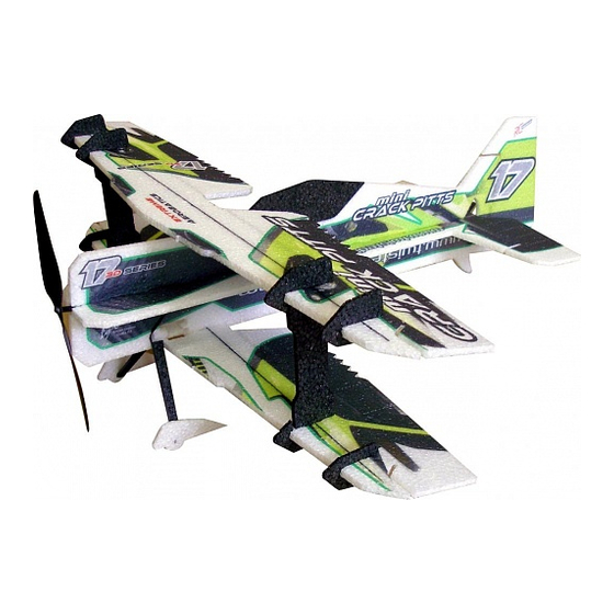
Mini Crack Pitts Building Instructions
Please refer to the respective Diagrams.
1. Create the main spar for each wing by gluing together 2 carbon strips 3x0.5x500 mm
side by side – only tiny drops of CA suffice. Make the spar slot in the wings by cutting
through in a straight line (along a metal ruler). Use very very sharp hobby knife. The
position of the cut is indicated by a shallow, laser cut mark. Keep your knife square to
the building board throughout all the cut. CA glue the spar into the slot. Repeat for
both the upper and lower wing.
2. In similar way, reinforce the elevator and the inter-wing struts with 3x0.5x100 and
3x0.5x110 carbon strips, respectively.
3. Cut the slots in the fuselage as indicated (make sure that you do not cut the fuselage all
the way across vertically in 2 parts), now do cut the fuselage horizontally in 2 parts
4. Glue the stabilizer/elevator to the horizontal fuselage part (the „backbone"), in upside-
down position. Glue the elevator servo into the backbone (ideally using Welders or
UHU-Por). Attach (glue) the lower fuselage part to the backbone.
5. Install (CA glue) the elevator control horn. Glue the pushrod supports into the
backbone.
6. There are 14 plastic „click-in" clevises included in the kit. You will need 12 and there
are 2 spares. Attach each clevis to the pushrod by a piece of heat-shrink tubing. When
you are happy with the lenght of the pushrod, neutrals etc, fix each clevis with a tiny
tiny drop of CA. Make sure the CA does not get into the pin – it would ruin it's
function. Ideally apply the CA when the clevis is in a vertical orientation with the pin
on top.
7. Install the elevator pushrod, glue in the rudder servo and the top part of the fuselage.
8. Create the vertical fuselage reinforcements (again, by first gluing CA strips side by
side just like with the wing spar), glue them into the fuselage.
9. Lower wing: attach the aileron extension horn to the aileron servo horn. Install the
aileron servo into the lower wing. Install the control horns (4 square holes in each),
centralize your aileron servo and install the aileron pushrods (see also Diag. 6). Glue
in the aileron connection arms. Glue the inter-wing struts into the lower wing (going
up, they have to lean to the front of the airplane).
10. Attach the lower wing to the fuselage as per the Diagram (on a margin of a
workbench, connect the fuselage with the wing, slide the plywood reinforcements on
the wing spar, apply thin CA glue).
11. Attach the upper wing as per the Diagram, all in upside down position, glue in the
inter-wing struts, install the aileron connection arms, adjust the lenght of the inter-
aileron pushrods and click them into the arms. Make sure the ailerons are all neutral
and parallel. Glue in the tailskid.
12. Assemble the Landing Gear as indicated. Glue the EPP LG „legs" to the carbon ones.
You can color the „half-wheels" on the wheel pants for better realism. Soak the
„wheels" in thin CA for better durability and lower friction.
13. Attach the Rudder to the fuselage. Glue in the control horn and the pushrod guides.
Install the pushrod just like you did with the elevator. Attach the Canopy.
14. Attach the motor mount to the fuselage. Install the motor and ESC.
15. Install the SFGs as per Diagram
16. Install the SFGs as per Diagram
17. Adjust your control throws as indicated. For first flights or if you are somewhat less
experienced 3D pilot, you may limit those throws to 50% or so.
Advertisement
Table of Contents

Related Manuals for RC Factory Mini Crack Pitts


Summary of Contents for RC Factory Mini Crack Pitts
- Page 1 Mini Crack Pitts Building Instructions Please refer to the respective Diagrams. 1. Create the main spar for each wing by gluing together 2 carbon strips 3x0.5x500 mm side by side – only tiny drops of CA suffice. Make the spar slot in the wings by cutting through in a straight line (along a metal ruler).
- Page 2 18. You may start with the CoG as indicated. It may be slightly adjusted to your personal taste.
- Page 3 Glue CA carbon 3x0,5x100mm carbon 3x0,5x110mm Glue CA Glue CA 2x carbon 3x0,5x500mm = 6x0,5x500mm Upper + lower wing cca 5mm Glue CA! (14pcs) Glue CA 2x carbon 3x0,5x70mm (6x0,5x70mm) Glue CA 0,8x330mm 2x carbon 3x0,5x110mm (6x0,5x110mm) 1x60mm Lower wing Upper + lower wing...
- Page 4 1x120mm Batt. 0,8x330mm Upper wing Lower wing Upper + lower wing Rud. 60° Elev. 60° Ail. 50° 135 mm...
Need help?
Do you have a question about the Mini Crack Pitts and is the answer not in the manual?
Questions and answers