Blodgett KLT-G Series Installation & Operation Manual
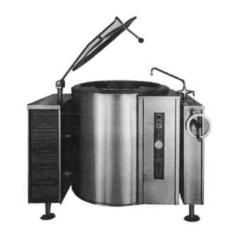
Klt-g series gas fired tri-leg tilting kettle
Hide thumbs
Also See for KLT-G Series:
- Installation operation & maintenance (32 pages) ,
- Installation operation & maintenance (23 pages)
Table of Contents
Advertisement
Quick Links
Advertisement
Table of Contents

Related Manuals for Blodgett KLT-G Series


Summary of Contents for Blodgett KLT-G Series
- Page 1 KLT-G Series GAS FIRED TRI-LEG TILTING KETTLE INSTALLATION – OPERATION – MAINTENANCE BLODGETT OVEN COMPANY IMPORTANT NOTES FOR INSTALLATION AND OPERATION www.blodgett.com 44 Lakeside Avenue, Burlington, Vermont 05401 USA Telephone: (802) 658-6600 Fax: (802) 864-0183 S00052 Rev A (5/04)
-
Page 2: Important Notes For Installation And Operation
It is recommended that this manual be read thoroughly and that all instructions be followed carefully. This is the safety alert symbol. It is used to alert you to potential personal injury hazards. Obey all safety messages that follow this symbol to avoid possible injury or death. -
Page 3: Table Of Contents
DESCRIPTION Important Notes For Installation and Operation 1.0 Service Connections 2.0 Installation 3.0 Operation 4.0 Cleaning Instructions 5.0 Maintenance 6.0 Service 7.0 Troubleshooting Appendix A, Material Safety Data Sheet TABLE OF CONTENTS PAGE... -
Page 4: Service Connections
1.0 SERVICE CONNECTIONS Supply gas through 3/4" pipe . A gas shut-off valve must be installed in supply piping convenient and adjacent to appliance. Unless other wise specified, Field Wire Electrical Connection to be 120 Volts, 60 Hertz single phase with grounding wire. COLD WATER: 3/8"(10mm) tubing to faucet (OPTIONAL) HOT WATER: 3/8"(10mm) tubing to faucet (OPTIONAL) MODEL... -
Page 5: Installation
2.0 INSTALLATION INSTALLATION CODES AND STANDARDS Installation must conform with local codes, or in the absence of local codes, with the National Fuel Gas Code, ANSI Z223.1/NFPA 54, or the Natural Gas and Propane Installation Code, CSA B149.1, as applicable. 1. - Page 6 INSTALLATION (Continued) All units must be installed in such a manner that the flow of combustion and ventilation air are not obstructed. Provisions for an adequate air supply must also be provided. Do not obstruct side of the unit, as combustion air enters through this area. Information on the construction and installation of ventilating hoods may be obtained from the standard for “Vapor Removal from Cooking Equipment”, NFPA No.
-
Page 7: Gas Connection
2.0 INSTALLATION (Continued) GAS CONNECTION The serial plate on the lower right side of the unit indicates the type of gas your unit is equipped to burn. Do NOT connect to any other gas type. A 3/4" NPT line is provided at the rear for the connection. Each unit is equipped with an internal pressure regulator which is set for 3.5"... -
Page 8: Water Connection
2.0 INSTALLATION (Continued) WATER CONNECTION On units equipped with an optional water fill valve connect a water line (minimum 1/4") to the valve with a 1/4" NPT female fitting. Units with dual (hot and cold) valves must have the hot water line connected to side with the hot water valve (red) and cold water line to the cold water valve (blue). -
Page 9: Performance Check
2.0 INSTALLATION (Continued) PERFORMANCE CHECK The following items should be checked before or within the first 30 days of operation by a qualified service technician. 1. Verify correct gas type against rating plate on unit. 2. Verify correct voltage, cycle and phase against rating plate on unit. 3. -
Page 10: Operation
3.0 OPERATION Contact the factory, the factory representative or a local service company to perform maintenance and repairs should the appliance malfunction. CAUTION: If you smell gas during the lighting procedure, immediately shut off the gas supply until the leak has been corrected. WARNING: In the event of main burner ignition failure, a 5 minute purge period must be observed prior to re-establishing ignition source. -
Page 11: Daily Shutdown
3.0 OPERATION (Continued) A. Lighting (Continued) If after 36 seconds the burner fails to ignite or the “ignition light goes out, the system goes into Safety Lockout. De-energize the system by setting the thermostat to “OFF” for five minutes and try again. 1. - Page 12 3.0 OPERATION (Continued) FRONT PANEL CONTROLS POWER SWITCH This switch turns the main power to the unit on and off. It must be turned on to heat the kettle. It should be turned off when the kettle will not be in use for long periods. (GREEN) IGNITION LIGHT This light is on whenever the main burner gas is on.
-
Page 13: Dial Setting
3.0 OPERATION (Continued) THERMOSTAT The thermostat selects the desired internal kettle operating temperature. The thermostat must be set at a desired setting in order for the burner to ignite. For Reference: DIAL SETTING PRESSURE GAUGE The pressure gauge indicates the internal operating pressure of the kettle. When cold, the gauge should point to the green vacuum zone. -
Page 14: Pressure Relief Valve
3.0 OPERATION (Continued) PRESSURE RELIEF VALVE The pressure relief valve is a safety device which prevents the internal kettle pressure from exceeding 50 psi. It should never be tampered with. DAILY OPERATION Daily operation should consist of turning on the power switch and setting thermostat for the desired temperature. - Page 15 3.0 OPERATION (Continued) GAS SAVING TIPS Use these reminders to help develop energy-saving procedures and habits. Using less natural or propane gas saves energy as well as money. 1. Turn off when not in use. 2. Limit preheat times. 3. Use lid when possible. 4.
-
Page 16: Cleaning Instructions
4.0 CLEANING INSTRUCTIONS WARNING: Disconnect the power supply to the appliance before cleaning or servicing. WARNING: Never spray water into electric controls or components! CAUTION: The equipment and its parts are hot. Use care when operating, cleaning and servicing. CAUTION: Do not use cleaning agents that are corrosive. Your kettle should be cleaned immediately after each use or when cooking a different product. -
Page 17: Draw-Off Valve Cleaning
4.0 CLEANING INSTRUCTIONS (Continued) DRAW-OFF VALVE CLEANING 1. If equipped with a tangent draw-off valve, turn the large hex nut on the draw-off valve counterclockwise until it is completely disengaged from the threads. Grasp the valve knob and slowly pull out the valve stem and disk. Do not allow the disk to come in contact with hard surfaces as it can be damaged and cause valve leakage. -
Page 18: What To Do If Surface Rust Appears
4.0 CLEANING INSTRUCTIONS (Continued) NOTICE: Draw-off valve has a vulcanized rubber coated stem for better sealing. Do not over tighten. This may cause the rubber to pull away from stem and permanently damage it. This is not covered under warranty. WHAT TO DO IF SURFACE RUST APPEARS Metal utensils should never be used as they will scratch the surface of the equipment and rust may begin to form. - Page 19 4.0 CLEANING INSTRUCTIONS (Continued) Soil and burn deposits which do not respond to the above procedure can usually be removed by rubbing the surface with SCOTCH-BRITE™ scouring pads or STAINLESS scouring pads. DO NOT USE ORDINARY STEEL WOOL as any particles left on the surface will rust and further spoil the appearance of the finish.
-
Page 20: Maintenance
5.0 MAINTENANCE Contact the factory, the factory representative or a local service company to perform maintenance and repairs. WARNING: Disconnect the power supply to the appliance before cleaning or servicing. Daily: 1. Wash exposed cleanable areas. Monthly: 1. Blower wheel inlet and motor air vent should be cleansed if an accumulation of dust or lint is obvious. -
Page 21: Service
6.0 SERVICE GENERAL When any difficulty arises always check that the unit has been connected to the gas supply type and voltage for which it was supplied. This can be done by examining the serial plate on the lower right side of the unit. It will list the gas type and voltage for which the unit was manufactured. -
Page 22: Pressure Switch
6.0 SERVICE (Continued) THERMOSTAT The thermostat adjustment should not be changed. Check the following before changing the thermostat. 1. With kettle cold, the pressure on the pressure gauge should read in the green vacuum zone (25 to 30 inches Hg vacuum). If not, see „Re-establishing Vacuum” section. 2. - Page 23 6.0 SERVICE (Continued) TO ADJUST PRESSURE SWITCH: 1. To obtain access to the pressure switch, the front panel must be removed. Remove the screws on bottom of the panel. Be sure to support the panel to avoid excessive strain on the wiring.
-
Page 24: For Reference
6.0 SERVICE (Continued) ADDING WATER (Low water light comes on) It may be necessary to replenish water in the jacket when the low water indicator comes on. Do so as follows: 1. Unit should be completely cold and off. 2. Lift handle of pressure relief valve to release vacuum in kettle. 3. - Page 25 6.0 SERVICE (Continued) RE-ESTABLISHING VACUUM Periodically check pressure gauge when kettle is cold. Reading should be in green vacuum zone (below 0 psi). Otherwise air is present and proper heating will not occur. Use the following procedure to remove air and re-establish vacuum: With the kettle empty, turn the thermostat knob to the highest temperature.
-
Page 26: Troubleshooting
7.0 TROUBLESHOOTING PROBLEM Motor will not run. Motor runs, no spark. Motor runs, spark present, no gas ignition. Low water light comes on. Relief valve opens. LOOK FOR S No current. Check that power is being supplied to the unit. S Defective thermostat or pressure switch. -
Page 27: Shutter Settings
Flame burns only about 6 seconds and shuts off. Short flame. Long hazy flame. Gas fails to shut off. NOTE: Loose, broken or grounded wiring may cause many of the symptoms listed. Check all wiring and make sure it is intact. Kettle Size/Gas Type 20 Gallon (80,000 BTU/HR) 30/40 Gallon (100,000 BTU/HR) - Page 28 Figure 1 Shutter setting at 2.0 Figure 2...
-
Page 29: Appendix A, Material Safety Data Sheet
PREPARATION INFORMATION: Prepared for use in Canada by: E H & S Product Regulatory Management Department 1. CHEMICAL PRODUCT AND COMPANY IDENTIFICATION IN CASE OF EMERGENCY: Product:: DOWFROST* HD HEAT TRANSFER FLUID, DYED Product Code: 04632 Effective Date: 2/20/01 DOW CHEMICAL CANADA INC. P.O. -
Page 30: Hazards Identification
Product: DOWFROST* HD HEAT TRANSFER FLUID, DYED Effective Date: 02/20/01, Date Printed: 07/10/02, MSD: 002239 3. HAZARDS IDENTIFICATION EMERGENCY OVERVIEW Clear yellow liquid. Odourless. Avoid temperatures above 450F, 232C. POTENTIAL HEALTH EFFECTS (See Section 11 for toxicological data.) EYE: May cause slight transient (temporary) eye irritation. Corneal injury is unlikely. Mists may cause eye irritation. - Page 31 Effective Date: 02/20/01, Date Printed: 07/10/02, MSD: 002239 4. FIRST AID EYES: SKIN: INGESTION: INHALATION: NOTE TO PHYSICIAN: 5. FIRE FIGHTING MEASURES FLAMMABLE PROPERTIES FLASH POINT: METHOD USED: AUTOIGNITION TEMPERATURE: NOT DETERMINED FLAMMABILITY LIMITS LFL: Not determined UFL: Not determined * or (R) indicates a trademark of The Dow Chemical Company.
- Page 32 MATERIAL SAFETY DATA SHEET Product: DOWFROST* HD HEAT TRANSFER FLUID, DYED Product Code: 04632 Effective Date: 02/20/01, Date Printed: 07/10/02, MSD: 002239 HAZARDOUS COMBUSTION PRODUCTS: During a fire, smoke may contain the original material in addition to unidentified toxic and/or irritating compounds. Hazardous combustion products may include and are not limited to carbon monoxide and carbon dioxide.
-
Page 33: Handling And Storage
MATERIAL SAFETY DATA SHEET Product: DOWFROST* HD HEAT TRANSFER FLUID, DYED Product Code: 04632 Effective Date: 02/20/01, Date Printed: 07/10/02, MSD: 002239 6. ACCIDENTAL RELEASE MEASURES (See Section 15 for Regulatory Information) PROTECT PEOPLE: Use appropriate safety equipment. For additional information, refer to Section 8, Exposure Controls/ Personal Protection. -
Page 34: Physical And Chemical Properties
Product: DOWFROST* HD HEAT TRANSFER FLUID, DYED Effective Date: 02/20/01, Date Printed: 07/10/02, MSD: 002239 EXPOSURE GUIDELINES: Propylene glycol: AIHA WEEL is 50 ppm total, 10 mg/m3 aerosol only. 9. PHYSICAL AND CHEMICAL PROPERTIES APPEARANCE/PHYSICAL STATE: ODOUR: VAPOUR PRESSURE: VAPOUR DENSITY: BOILING POINT: SOLUBILITY IN WATER/MISCIBILITY: SPECIFIC GRAVITY OR DENSITY:... - Page 35 Product: DOWFROST* HD HEAT TRANSFER FLUID, DYED Effective Date: 02/20/01, Date Printed: 07/10/02, MSD: 002239 SKIN: INGESTION: MUTAGENICITY: 12. ECOLOGICAL INFORMATION (For detailed Ecological data, write or call the address or non-emergency number shown in Section 1.) ENVIRONMENTAL FATE MOVEMENT & PARTITIONING: Based largely or completely on data for major component(s). Bioconcentration potential is low (BCF less than 100 or Log Pow less than 3).
-
Page 36: Transport Information
MATERIAL SAFETY DATA SHEET Product: DOWFROST* HD HEAT TRANSFER FLUID, DYED Effective Date: 02/20/01, Date Printed: 07/10/02, MSD: 002239 FOR UNUSED & UNCONTAMINATED PRODUCT, the preferred options include sending to a licensed, permitted: recycler, reclaimer, incinerator or other thermal destruction device. As a service to its customers, Dow can provide names of information resources to help identify waste management companies and other facilities which recycle, reprocess or manage chemicals or plastics, and that manage used drums. - Page 37 MATERIAL SAFETY DATA SHEET Product: DOWFROST* HD HEAT TRANSFER FLUID, DYED Effective Date: 02/20/01, Date Printed: 07/10/02, MSD: 002239 U.S. REGULATIONS SARA 313 INFORMATION: To the best of our knowledge, this product contains no chemical subject to SARA Title III Section 313 supplier notification requirements. SARA HAZARD CATEGORY: This product has been reviewed according to the EPA “Hazard Categories”...
-
Page 38: Canadian Regulations
MATERIAL SAFETY DATA SHEET Product: DOWFROST* HD HEAT TRANSFER FLUID, DYED Product Code: 04632 Effective Date: 02/20/01, Date Printed: 07/10/02, MSD: 002239 CANADIAN REGULATIONS WHMIS INFORMATION: The Canadian Workplace Hazardous Materials Information System (WHMIS) Classification for this product is: This product is not a “Controlled Product” under WHMIS. CANADIAN ENVIRONMENTAL PROTECTION ACT (CEPA) This product contains one or more substances which are not listed on the Canadian Domestic Substances List (DSL).
Need help?
Do you have a question about the KLT-G Series and is the answer not in the manual?
Questions and answers