Blodgett KLT-G Series Installation Operation & Maintenance
Gas tilting floor kettle
Hide thumbs
Also See for KLT-G Series:
- Installation & operation manual (38 pages) ,
- Installation operation & maintenance (23 pages)
Table of Contents
Advertisement
Quick Links
Advertisement
Table of Contents

Related Manuals for Blodgett KLT-G Series


Summary of Contents for Blodgett KLT-G Series
- Page 1 KLT-G Series GAS TILTING FLOOR KETTLE INSTALLATION - OPERATION - MAINTENANCE BLODGETT OVEN COMPANY www.blodgett.com 44 Lakeside Avenue, Burlington, Vermont 05401 USA Manufacture Service Questions: 866-518-3977 PART NUMBER 170097 REV B (04/11)
- Page 2 THIS MANUAL MUST BE RETAINED FOR FUTURE REFERENCE. READ, UNDERSTAND AND FOLLOW THE INSTRUCTIONS AND WARNINGS CONTAINED IN THIS MANUAL. FOR YOUR SAFETY DO NOT STORE OR USE GASOLINE OR OTHER FLAMMABLE vAPORS AND LIqUIDS IN THE vICINITY OF THIS OR ANY OTHER APPLIANCE. POST IN A PROMINENT LOCATION INSTRUCTIONS TO BE FOLLOWED IN THE EvENT USER SMELLS GAS.
-
Page 3: Important Operator Warnings
IMPORTANT - READ FIRST - IMPORTANT CAUTION: BE SURE ALL OPERATORS READ, UNDERSTAND AND FOLLOW THE OPERATING INSTRUCTIONS, CAUTIONS, AND SAFETY INSTRUCTIONS CONTAINED IN THIS MANUAL. WARNING: THIS UNIT IS INTENDED FOR USE IN THE COMMERCIAL HEATING, COOKING AND HOLDING OF WATER AND FOOD PRODUCTS, PER THE INSTRUCTIONS CONTAINED IN THIS MANUAL. - Page 4 IMPORTANT - READ FIRST - IMPORTANT WARNING: KEEP WATER AND SOLUTIONS OUT OF CONTROLS AND ELECTRICAL EqUIPMENT. NEvER SPRAY OR HOSE THE SUPPORT HOUSING OR ELECTRICAL CONNECTIONS. CAUTION: MOST CLEANERS ARE HARMFUL TO THE SKIN, EYES, MUCOUS MEMBRANES AND CLOTHING. PRECAUTIONS SHOULD BE TAKEN.
-
Page 5: Table Of Contents
Table of Contents Important Operator Warnings .............page 1-2 References..................page 3 Equipment Description..............page 4 Inspection and Unpacking ............page 5 Installation ................... page 6-7 Operation ................page 8-10 Sequence of Operation ..............page 11 Cleaning.................. page 12-13 Maintenance................page 14-16 Troubleshooting.............. -
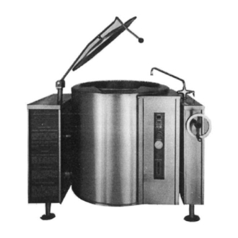
Page 6: Equipment Description
Equipment Description The Blodgett KLT-G is a floor-mounted, tilting, steam jacketed kettle with a thermostatically controlled, self-contained, gas-heated steam source and appropriate controls, mounted on a sturdy base. The kettle is available in 20, 40, 60 or 80 gallon capacities. -
Page 7: Inspection And Unpacking
Inspection & Unpacking CAUTION The unit will arrive in a heavy shipping carton and will be bolted or banded to a skid. SHIPPING STRAPS ARE UNDER TENSION Immediately upon receipt, inspect the carton carefully for exterior damage. AND CAN SNAP BACK WHEN CUT. TAKE CARE TO AVOID PERSONAL INJURY OR Carefully cut any polyester straps around the carton and detach the sides of the box from DAMAGE TO THE UNIT BY STAPLES LEFT... -
Page 8: Installation
Installation WARNING For efficient performance the kettle must be installed in a well-ventilated area. Items THE UNIT MUST BE INSTALLED BY which might restrict or obstruct the flow of air for combustion and ventilation must be PERSONNEL WHO ARE QUALIFIED TO WORK removed. - Page 9 Installation WARNING The gas supply and unit’s installation must conform with local codes or in the DO NOT CONNECT ANY PIPING TO absence of local codes, with the National Fuel Gas Code, ANSI Z223.1/NFPA THE PRESSURE RELIEF VALVE. THE VALVE 54 (current edition), or the Natural Gas and Propane Installation Code CSA MUST BE FREE TO VENT STEAM AS 149.1(current edition), as applicable.
-
Page 10: Operation
Operation Controls Operator controls for the kettle are: Manual gas valve (on gas line behind the unit), which controls the supply of gas from the main to the unit. On-Off (Toggle) Switch. This controls the supply of electric power to the control circuits. - Page 11 Operation CAUTION To Shut Down Kettle: DO NOT TILT KETTLE WITH LIFT-OFF Turn thermostat dial to OFF. COVER IN PLACE. COVER MAY SLIDE OFF, CAUSING INJURY TO OPERATOR. Turn toggle switch to OFF. WARNING For a prolonged shut-down: AVOID ALL DIRECT CONTACT WITH HOT Follow the procedure above.
- Page 12 Operation CAUTION Basket Insert DO NOT OVER FILL THE KETTLE WHEN An optional kettle basket insert set will assist in cooking water-boiled COOKING, HOLDING OR CLEANING. KEEP products including eggs, potatoes, vegetables, shell fish, pasta and LIQUIDS AT A MINIMUM OF 2-3” (5-8 CM) rice.
-
Page 13: Sequence Of Operation
Sequence of Operation The following “action-reaction” outline is provided to help understand how the kettle works. When the power switch is turned on, it starts the spark igniter and opens the automatic valve for the pilot burner. The spark ignites a pilot flame, which heats the sensor. -
Page 14: Cleaning
Cleaning WARNING Suggested Cleaning Supplies: KEEP WATER AND SOLUTIONS AWAY FROM Cleaner, such as Klenzade HC-10 or HC-32 from ECOLAB, Inc. or CONTROLS AND ELECTRICAL EQUIPMENT. equivalent. NEVER SPRAY THE SUPPORT HOUSING OR Kettle brushes in good condition. ELECTRICAL CONNECTIONS. Sanitizer such as Klenzade XY-12. - Page 15 Cleaning NOTICE The outside of the unit may be polished with a stainless steel cleaner NEVER LEAVE A CHLORINE SANITIZER IN such as “Zepper” from Zep Manufacturing Co. or equivalent. CONTACT WITH STAINLESS STEEL SURFACES LONGER THAN 30 MINUTES. When equipment needs to be sanitized, use a solution equivalent to one LONGER CONTACT CAN CAUSE that supplies 200 parts per million available chlorine.
-
Page 16: Maintenance
Maintenance WARNING NOTICE: Contact an authorized representative when repairs are required. WHEN TESTING, AVOID ANY EXPOSURE TO THE STEAM BLOWING OUT OF THE Periodic Maintenance SAFETY VALVE. DIRECT CONTACT A Maintenance & Service Log is provided at the back of this manual with the COULD RESULT IN SEVERE BURNS. - Page 17 Maintenance Jacket Vacuum/Removing Air from Jacket When the kettle is cold, a positive pressure reading on the pressure/vacuum gauge or a reading near zero indicates that there is air in the jacket. Air in the jacket acts as an insulator, and slows kettle heating. To remove air: Start the unit.
- Page 18 Maintenance WARNING Water Treatment Procedure TO AVOID INJURY, READ AND FOLLOW ALL A Maintenance & Service Log is provided at the back of this manual with the PRECAUTIONS ON THE LABEL OF THE warranty information. Each time maintenance is performed on your kettle, enter WATER TREATMENT COMPOUND.
-
Page 19: Troubleshooting
Troubleshooting Your kettle is designed to operate smoothly and efficiently if properly maintained. However, the following is a list of checks to make in the event of a problem. Wiring diagrams are furnished inside the service panel and in this manual. If an item on the list is followed by X, the work should be done by a qualified service representative. - Page 20 Troubleshooting WHAT TO CHECK SYMPTOM X indicates items which must be performed by an authorized technician. Spark is present but the pilot Auth Service a. That the pilot valve is securely connected to terminals.X will not light. Rep Only b. For 24 VAC at terminals PV and PV/MV. If 24V is not present, replace the ignition control module.X b.
-
Page 21: Parts Lists
Parts List Stand & Housing Assy. - Smaller Sizes Description Part No. STAND AND HOUSING ASSY. 123813 CABINET SIDE PANEL 047882 STAND CLADDING MS96694 BASE ASSEMBLY MS96698 HOUSING WELDMENT ASSY. MS47332 HOUSING CLADDING, 20 GAL. 123810 HOUSING CLADDING, 123811 40 AND 60 GAL. TRAY LINER 001475 NUT HEXAGON 1/2-13... - Page 22 Parts List Stand & Housing Assembly - 80 Gal. Description Part No. STAND & HOUSING ASSEMBLY FRAME ASSEMBLY 80 GAL. 149257 WELDMENT, STAND 149775 CLADDING WELDMENT, PEDESTAL 149242 TRAY, LINER 150253 CLADDING, PEDESTAL 149241 ASSEMBLY COVER, TOP PEDESTAL 150252 CLADDING WASHER, PLAIN 1/2”...
- Page 23 Parts List Gas valve Piping & Btm. Components Assembly Assy. - Smaller Sizes Description Part No. GAS VALVE PIPING & 127369 BOTTOM COMPS. TUBE, COPPER, 1/2” 007334 ELBOW, FEMALE, 055634 90 DEG. 1/2 NPT THERMOSTAT, ELECTRIC 009730 ELBOW, 90 DEG 1/2 NPT 008747 NIPPLE, 1/2 NPT X 005552...
- Page 24 Parts List Gas valve Piping & Btm. Components Assembly Assy. - 80 Gal. Description Part No. GAS VALVE PIPING & BOTTOM COMPS. TUBE, PILOT 150949 FITTING COMPRESSION 057217 TUBE, VALVE OUTLET. 149765 80 GAL. ELECTRODE WATER LEVEL 076526 BRACKET SUPPORT 065382 SCREW PAN HEAD 005764...
- Page 25 Parts List Burner & Flame Sensor Assembly Description Part No. BURNER AND FLAME SEN- 123814 SOR ASSY. - 40 GAL. BAFFLE PLATE 123498 WASHER LOCK 005655 NUT HEX 005601 BURNER BRACKET SUPPORT 1017010 BURNER BRACKET 117013 BURNER ASSEMBLY - 090644 60 GAL.
- Page 26 Parts List Flue Stack Assembly - Smaller Sizes Description Part No. FLUE STACK ASSEMBLY 117034 FLUE, TOP SECTION OF 117029 TOP PLATE FLUE, BOTTOM SECTION 117033 OF TOP PLATE FLUE, FRONT SECTION 117032 FLUE, MAIN BODY 117031 SCREW, TRUSS HEAD 072189 OM-KLT-G...
- Page 27 Parts List Flue Stack Assembly - 80 Gal. Description Part No. FLUE STACK ASSEMBLY ASSY. FLUE STACK 149220 MAIN BODY FLUE, FRONT PANEL. 150927 WELDMENT FLUE STACK, BOTTOM 149236 SECTION FLUE, TOP SECTION 149222 SCREW TRUSS HEAD 072189 MACHINED 10-32 X 1/2” L. OM-KLT-G...
- Page 28 Parts List Electrical Panel Description Part No. ELECTRICAL PANEL 123736 WATER LEVEL CONTROL 122192 TRANSFORMER 75A 24V 106233 SEC., 120V PRI TRANSFORMER 75A 24V 106234 SEC., 208/240V PRI SCREW, BUTTON HEAD #8- 096317 32 X 0.25 LG TERMINAL BLOCK, 003887 2 POLE #4 - #18 AWG FUSE HOLDER 3AG W/0.
- Page 29 Parts List Arm & Module Box Assembly Description Part No. ARM AND MODULE 127734 BOX ASSEMBLY CONDUIT NUT, 1/2” 005487 SCREW #8-32 X 3/8” 005764 BOX, SPARK IGNITION 123775 MODULE GASKET, IGNITION 104941 MODULE BOX SPARK IGNITION MODULE 085153 HEX NUT W/SHAKEPROOF 071289 WASHER CONDUIT, PLASTIC,...
-
Page 30: Service Log
Service Log Model No: Purchased From: Serial No: Location: Date Purchased: Date Installed: Purchase Order No: For Service Call: Date Maintenance Performed Performed By OM-KLT-G... - Page 31 Service Log Model No: Purchased From: Serial No: Location: Date Purchased: Date Installed: Purchase Order No: For Service Call: Date Maintenance Performed Performed By OM-KLT-G...
- Page 32 BLODGETT OVEN COMPANY www.blodgett.com 44 Lakeside Avenue, Burlington, Vermont 05401 USA Telephone: 866-518-3977 PART NUMBER 170097 REV B (04/11)
Need help?
Do you have a question about the KLT-G Series and is the answer not in the manual?
Questions and answers