
Related Manuals for Silvan Selecta 190547


Summary of Contents for Silvan Selecta 190547
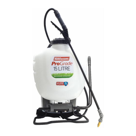
- Page 1 Instruction Manual MAN190547 REV A 23/04/18 PRO GRADE NO LEAKS SPRAYER 15L 190547, 190550...
-
Page 2: Safety Instructions
Safety Instructions WARNINGS • This sprayer is designed and manufactured solely for the purpose of applying agricultural chemicals. Under no circumstances may it be used for any other purpose. • Read owner’s manual completely before operating this sprayer. • Test the sprayer with water before using chemicals •... - Page 3 Assembly Assemble Extension, Shut-Off, Nozzle and Spray Optimizer: 1. Install the extension “wand” onto the shut- off assembly and tighten the nut securely. Figure B (See Figure A) 2. Install Spray Optimiser for low pressure (low Figure A drift) applications. This will help prevent Figure C weed killer formulas from drifting into undesired areas.
- Page 4 Assembly (cont.) ASSEMBLE PUMP HANDLE: Step 1: Insert handle onto the drive shaft. Step 2: Line up holes so that pump handle is angled upward. Upward position Step 1 Step 2 Step 3: Thread hex bolt through pump handle and drive shaft, tighten with a 13mm or adjustable wrench.
-
Page 5: Operation
Operation Always conduct a test using clean water before mixing chemicals. Filling: Always refer to chemical manufacturer for proper mixture. 1. Remove the cap from the tank. 2. Make sure the filter basket is in place in the neck of the tank. The filter basket includes the seal and must be in place to prevent leaks. -
Page 6: Installation
Assembly Sprayer Storage: 1. Never store sprayer with pressure in chamber or liquid in any part of sprayer. 2. Sprayer tank should be hung upside down, with the cap removed, to dry completely. 3. Do not store or leave any solution in the tank after use. 4. - Page 7 Servicing Prior To Servicing And/Or Repairs: 1. Empty contents of tank. 2. While squeezing shut-off, pump sprayer until all liquid is expelled. 3. Continue squeezing shut-off without pumping to release all air pressure. Sprayer Servicing Steps: 1. Unscrew cap from tank. Remove and replace check valve. (See Figure 1) 2.
- Page 8 Servicing (cont.) 7. Pull upward to slide piston rod out of pump. (See Figure 7) 8. While holding onto the pump, use an adjustable wrench to unthread pump nut from pump. Remove nut, hose and barb assembly. (See Figure 8) 9.
-
Page 9: Harness Installation
Servicing (cont.) 16. Attach pivot clip to piston rod and insert hitch pin. Note orientation of piston rod must match the pivot clip. (See Figure 16) 17. Reassemble carry handle onto tank. Tighten all (6) screws. (See Figure 5) 18. To reinstall the agitator, line the notch up on the agitator with the wedge on piston rod and snap into place. -
Page 10: Troubleshoot
Troubleshoot PROBLEM REASON SOLUTION Sprayer starts to spray when Squeeze shut-off lever and disengage pumping sprayer will not Shut-off lock is engaged. the lock, See Pressurising and stop spraying when shut-off Spraying section. lever is released. 1.Install pressure chamber as 1. -
Page 11: Spare Parts
Spare Parts Code Description 183864 Shoulder Harness 183862 Nozzle Kit 183859 Trigger Assembly (Shut Off Assembly) 183863 Trigger Assembly& Wand Repair Kit 183867 Pump Handle 183860 Stainless Steel Wand 183861 Poly Wand 183865 183866 Filter Basket 183868 Knapsack Pump Repair Kit...
Need help?
Do you have a question about the 190547 and is the answer not in the manual?
Questions and answers