Table of Contents
Advertisement
Quick Links
Advertisement
Table of Contents

Related Manuals for BOMBARDIER SKI-DOO MX-Z Renegade 600 HO SDI


Summary of Contents for BOMBARDIER SKI-DOO MX-Z Renegade 600 HO SDI
- Page 2 This Operator’s Guide and Safety Videocassette should remain with the unit at time of resale. In USA, products are distributed by Bombardier Motor Corporation of America. In Canada, products are distributed by Bombardier Inc. The following are trademarks of Bombardier Inc. or its subsidiaries. ®...
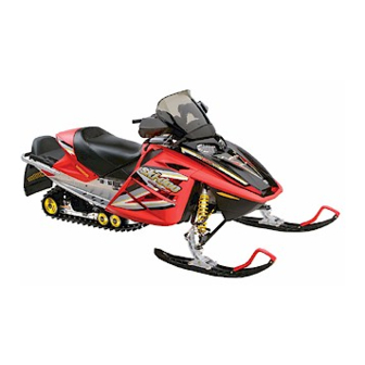
- Page 3 2005 SKI-DOO OPERATOR’S GUIDE ® This guide is applicable to MX-Z Renegade 600 HO SDI.
- Page 4 FOREWORD Congratulations on your purchase of a new SKI-DOO snowmobile. Whatever model you have chosen, it is backed by the Bombardier warranty and a network of authorized SKI-DOO snowmobile dealers ready to provide the parts, service or accessories you may require.
- Page 5 The information and components/system descriptions contained in this guide are correct at time of publication. Bombardier Inc., howev- er maintains a policy of continuous improvement of its products with- out imposing upon itself any obligation to install them on products previously manufactured.
-
Page 6: Table Of Contents
LAWS AND REGULATIONS ............ SUMMARY OF ACCIDENT PREVENTION PRACTICES ..ENVIRONMENT ............... VEHICLE INFORMATION LIST OF HOT PARTS..............LIST OF MOVING PARTS ............BOMBARDIER LIMITED WARRANTY NORTH AMERICA: ® 2005 SKI-DOO SNOWMOBILES..........FREQUENTLY ASKED QUESTIONS ........AUTHORIZED SKI-DOO DEALERS ......... - Page 7 11) Engine Cut-Out Switch ............12) Headlamp Dimmer Switch ........... 13) High Beam Pilot Lamp (Blue) ..........14) Oil Pilot Lamp............... 15) Low Battery Voltage Pilot Lamp .......... 16) Engine Management System (EMS) Pilot Lamp....17) Rewind Starter Handle ............18) Speedometer ...............
- Page 8 OPERATING INSTRUCTIONS ..........102 Principle of Operation..............102 Starting the Engine..............103 Emergency Starting..............103 Shutting Off the Engine............. 105 VEHICLE WARM-UP ..............106 RIDING THE VEHICLE .............. 106 HOW TO RIDE ................107 TERRAIN/RIDING VARIATIONS ..........110 POST-OPERATION CARE ............117 SPECIAL OPERATIONS ............
- Page 9 Track Condition ................139 Track Tension and Alignment............. 140 Steering and Front Suspension..........144 Wear and Condition of Skis and Runners ........144 Exhaust System ................. 144 Air Filter Cleaning............... 145 Headlamp Beam Aiming ............146 Bulb Replacement..............146 TOWING THE VEHICLE ............148 TRANSPORTING THE VEHICLE ..........
-
Page 10: Safety Measures
SAFETY MEASURES Observe the Following Warnings: The performance of some snowmobiles may significantly exceed that of other snowmobiles you have operated. Therefore, use by novice or inexperienced operators is not recommended. Basic training is required for the safe operation of any snowmobile. Study your Operator’s Guide paying particular attention to cautions and warnings. - Page 11 Never ride after consuming drugs or alcohol or if you feel tired or ill. Operate your snowmobile prudently. Speeding can be fatal. In many cases, you cannot react or respond quickly enough to the unexpected. Always ride at a speed which is suitable to the trail, weather conditions and your own ability.
- Page 12 Use of Rotax snowmobile engines in other than SKI-DOO snowmobiles is not recommended or autho- rized by Bombardier Inc.or its subsidiaries. Electronic reverse (RER ) models only: The shifting to reverse mode on these snowmobiles is done by the push of the RER button when the engine is running.
-
Page 13: Safety Information
SAFETY INFORMATION SAFETY INFORMATION... -
Page 14: Introduction
INTRODUCTION This safety information section includes safety WARNINGS which if not followed may result in serious personal injury including the pos- sibility of death. After reading, please keep this Operator’s Guide with the snowmo- bile. If the snowmobile is resold, please give the guide to the new owner for his awareness. -
Page 15: Safety Labeling
SAFETY LABELING Safety standards for snowmobiles have been adopted by the Snowmo- bile Safety and Certification Committee (SSCC) of which Bombardier is a proud participating member. Assurance that your snowmobile meets these standards is easily checked by locating the Certification Label on a right vertical portion of the vehicle. - Page 16 HOW TO DRESS Proper snowmobile clothing should be worn. It should be comfort- able and not too tight. Always check the weather forecast before you go on a ride. Dress for the coldest weather expected. Thermal under- wear next to the skin also provides an important layer of insulation. Approved helmets are recommended at all times.
-
Page 17: A Word To All Snowmobilers
A WORD TO ALL SNOWMOBILERS Everyone is a beginner the first time he sits behind the controls of a snowmobile regardless of previous experience in driving an automo- bile, a motorcycle or a motorboat. The safe use of your snowmobile is dependent on many conditions such as visibility, speed, weather, environment, traffic, vehicle condition and the condition of the driver. -
Page 18: Laws And Regulations
TRANSPORTING AND TOWING Follow transporting and towing instructions explained further in this guide. LAWS AND REGULATIONS Federal, state, provincial and local government agencies have enact- ed laws and regulations pertaining to the safe use and operation of snowmobiles. It is your responsibility as a snowmobiler to learn and obey these laws and regulations. - Page 19 Be aware of inherent risks associated with riding off trails, such as avalanche and other natural or man made hazards or obstacles. Avoid road traveling. If you must do so and it is permitted, reduce speed. The snowmobile is not designed to operate or turn on pav- ing.
- Page 20 Drinking and driving demonstrates a most irresponsible at- titude not only to others but to yourself. Legislators and the popu- lation in general don’t tolerate it for good reason and BOMBARDIER Recreational Products doesn’t either! Wildlife compliments your snowmobiling day. Snowmobile tracks provide firm ground over which animals can travel from area to area.
- Page 21 Help us lead it down the right path! From all of us at BOMBARDIER Recreational Products, thank you for doing your share. SAFETY INFORMATION...
-
Page 22: Environment
Recognizing the importance of this issue and the need for snowmo- bilers to do their share in preserving areas that make it possible to enjoy our sport, BOMBARDIER Recreational Products has developed the “Light Treading Is Smart Sledding” campaign for snowmobilers. - Page 23 Respect wildlife and be particularly sensitive of animals that are rear- ing young or suffering from food shortage. Stress can sap scarce energy reserves. Refrain from riding in areas where only animals are intended to tread! Obey gate closures and regulatory signs and remember, light tread- ers don’t litter! Stay out of wilderness areas.
-
Page 24: Vehicle Information
VEHICLE INFORMATION... -
Page 25: List Of Hot Parts
LIST OF HOT PARTS All power train components. LIST OF MOVING PARTS All transmission, suspension and steering parts. -
Page 26: Bombardier Limited Warranty North America: 2005 Ski-Doo Snowmobiles
All genuine BOMBARDIER parts and accessories, installed by an autho- rized BOMBARDIER dealer (as hereinafter defined) at the time of delivery of the 2005 SKI-DOO snowmobile, carry the same warranty as that of the snowmobile. - Page 27 3. CONDITIONS TO HAVE WARRANTY COVERAGE This warranty coverage is available only on 2005 SKI-DOO snowmobile purchased as new and unused by its first owner from a BOMBARDIER dealer authorized to distribute SKI-DOO products in the country in which the sale occurred (hereinafter “BOMBARDIER dealer”), and then only after the BOMBARDIER specified pre-delivery inspection process is com- pleted and documented.
- Page 28 (2) days of the appearance of a defect, and provide it with reasonable access to the product and reasonable opportunity to repair it. The custom- er must also present to the BOMBARDIER dealer, proof of purchase of the product and must sign the repair/work order prior to the start of the repair in order to validate the warranty repair.
- Page 29 BOMBARDIER. BOMBARDIER reserves the right to modify this warranty at any time, being understood that such modification will not alter the warranty conditions ap- plicable to the products sold while this warranty is in effect.
-
Page 30: Frequently Asked Questions
SKI-DOO dealer with all the necessary data to complete warranty claim forms. b) be advised by Bombardier should there be a safety recall or particular warranty campaign. c) be contacted much faster by the police, the minute they find your stolen snowmobile (if such a case occurs). - Page 31 Q: Are “ Genuine” Bombardier replacement parts used in warranty repairs covered by warranty? A: Yes. When installed by an authorized SKI-DOO dealer, any “Genuine”...
-
Page 32: Authorized Ski-Doo Dealers
AUTHORIZED SKI-DOO DEALERS For Canada and USA Only To find the nearest authorized SKI-DOO dealer, dial: 1 800 375-4366 or visit our web site at WWW.SKIDOO.COM. -
Page 33: How To Identify Your Snowmobile
HOW TO IDENTIFY YOUR SNOWMOBILE Vehicle Description Decal Vehicle description decal is located on right hand side of tunnel. A33H01A TYPICAL 1. Vehicle description decal A00A6MA VEHICLE DESCRIPTION DECAL 1. Manufacturer name 2. Manufacturing date 3. Vehicle identification number (VIN) 4. -
Page 34: Serial Numbers
These numbers are required by the authorized SKI-DOO dealer to complete warranty claims properly. No warranty will be allowed by Bombardier if the engine serial number or vehicle identification number (VIN) is removed or mutilated in any way. - Page 35 Engine Serial Number Location A32C01B 2-STROKE LIQUID COOLED MODELS 1. Engine serial number...
-
Page 36: On-Vehicle Important Instructions
ON-VEHICLE IMPORTANT INSTRUCTIONS The following instructions are on your snowmobile. If missing or dam- aged, the decals can be replaced free of charge. See an authorized SKI-DOO dealer. Please read the following instructions carefully before operating this snowmobile. A33A1ZC TYPICAL — LOCATION OF IMPORTANT INSTRUCTIONS... - Page 37 Instruction 1 A32A24A...
- Page 38 Instruction 2 A01A2EA Instruction 3 A01A2FA...
- Page 39 Instruction 4 A01A2GA TYPICAL Instruction 5 A32A1GA...
- Page 40 Instruction 6 A32A1HA Instruction 7 A32A1EA...
- Page 41 Instruction 8 DO NOT SIT HERE / NE PAS S’ASSEOIR ICI A33H02A Instruction 9 A33H11A...
- Page 42 Instruction 10 A33A20A Instruction 11 EMISSION CONTROL INFORMATION THIS ENGINE IS CERTIFIED TO OPERATE ON UNLEADED GASOLINE AND CONFORMS TO XXXX U.S. EPA REGULATIONS FOR SNOWMOBILE SI ENGINES. ENGINE FAMILY: ............ XXXXXXXXXXX FEL: ............XXg/kW-hr HC+NO XXXg/kW-hr CO ENGINE DISPLACEMENT:......... XXXX cc EXHAUST EMISSION CONTROL SYSTEM: ....
-
Page 43: Controls/Instruments/Equipment
CONTROLS/INSTRUMENTS/EQUIPMENT NOTE: Some controls/instruments/equipment are optional on the MX-Z Renegade. A33A1ZD TYPICAL... - Page 44 A33A1FB TYPICAL...
-
Page 45: Throttle Lever
6-10 20-21-22 A32A15D TYPICAL 1) Throttle Lever Located on the right hand side of handlebar and designed to be thumb activated. When squeezed, it increases the engine speed and engages the transmission. When released, engine speed returns au- tomatically to idle. WARNING Test the throttle lever operation each time before starting the engine. -
Page 46: Brake/Parking Brake (Red) Pilot Lamp
WARNING Make sure parking brake is fully disengaged before operating the snowmobile. When you ride the vehicle, brake pads that are caused to drag by a continuous pressure on the lever may cause damage to the brake system and cause loss of braking capacity and/or fire. To engage mechanism, squeeze brake lever and maintain while pull- ing locking lever with a finger. -
Page 47: Rer Button
5) RER Button General When the engine is running, depressing the RER button will com- mand the engine to reverse crankshaft rotation as driving the snow- mobile in reverse is achieved by changing the direction of rotation of the engine, not by shifting the chaincase in reverse gear. When depressing the RER button, the MPEM (Multi-Purpose Elec- tronic Module) will practically slow down the engine RPM to a stop and advance the ignition timing to cause crankshaft rotation revers-... -
Page 48: Reverse Pilot Lamp
DESS/RER pilot lamp and warning buzzer will stop. Apply throttle slowly and evenly. Allow drive pulley to engage then accelerate carefully. RER Modification at High Altitude General At high altitude, the RER system needs a different engine timing curve to work properly. Operation The MX-Z Renegade 600 HO SDI is equipped with a Engine Manage- ment System (EMS). - Page 49 A33H12A ONE SIDE SHOWN — REARWARD POSITION 1. Bolts retaining windshield assembly Remove steering cover and console cap. A33H05B 1. Steering cover 2. Console cap...
- Page 50 Unscrew 4 bolts retaining console. A33H06A 1. Bolts retaining console...
- Page 51 Slightly lift console to gain access to electrical connector housings. Unplug the 2 large connector housings and the separate 3 wire con- nector. A33H07A TYPICAL 1. Large connector housings Remove console. Remove 2 bolts retaining top of steering column. A33H08A STEERING COLUMN IN REARWARD POSITION 1.
- Page 52 Move steering column to forward position. A33H09B STEERING COLUMN IN FORWARD POSITION 1. Longer bolt Reinstall the 2 bolts. Always install the longer bolt on thicker portion to be bolted. Use new lock nuts. Torque nuts to 24 N• m (18 lbf• ft). Reconnect the electrical connectors and reinstall all removed parts.
- Page 53 Position of console cap will be inverted. Instead of being above it will be beneath steering column. A33H0AA CONSOLE CAP INSTALLED BENEATH STEERING COLUMN Reinstall windshield assembly to handlebar. Refer to WINDSHIELD ADJUSTMENT below. A33H04A ONE SIDE SHOWN — FORWARD POSITION 1.
- Page 54 Readjust throttle lever housing and brake lever housing accordingly to optimal angle so that you will not need to release your grip to operate levers. WARNING Adjust with vehicle at rest in a safe place. Securely retighten all fasteners. Never rotate throttle lever to operate with fingers instead of thumb.
- Page 55 Windshield Adjustment The windshield can be adjusted to properly fit with console. Before adjusting windshield, make sure it is installed on the proper bracket slots according to steering column position. See above photos. Slots in brackets allow different windshield positions. Move wind- shield to fit with console.
-
Page 56: Holding Strap
A33H18A PROPER FIT OF WINDSHIELD VERSUS CONSOLE 1. In line A. 8 to 12 mm (3/8 to 1/2 in) 8) Holding Strap Holding strap provides a grip for driver when side-hilling. WARNING This strap is not for towing, lifting or other purpose than tem- porary use as a grab bar during side-hilling. - Page 57 Operation Attach to clothing eyelet then snap tether cord cap over post before starting engine. A06H1YA TYPICAL 1. Snap over post 2. Attach to eyelet If emergency engine shut off is required, completely pull tether cord cap from post. A06H1XA TYPICAL...
- Page 58 Tether cut-out switch is part of tether cut-out system. This system serves 3 functions. It shuts off engine preventing snowmobile to runaway if the operator falls off the vehicle accidently. Through the DESS (Digitally Encoded Security System), it acts as a lock by preventing unauthorized use of your snowmobile thus de- terring theft.
-
Page 59: Dess Pilot Lamp
DESS Pilot Lamp Codes DESS pilot lamp blinking slowly (one time per 1.5 seconds) means that a bad connection has been detected. Vehicle can not be driven. To check for bad connection, remove tether cord cap. Make sure the tether cord cap is free of dirt or snow. Reinstall cap and restart engine. If a blink per 1.5 seconds still occurs contact an authorized dealer. -
Page 60: Headlamp Dimmer Switch
A33E03A TYPICAL 1. ON 2. OFF All operators of the snowmobile should familiarize themselves with the function of this device by using it several times on first outing and whenever stopping the engine there-after. This engine cut-out pro- cedure will become a reflex and will prepare operators for emergency situations requiring its use. -
Page 61: High Beam Pilot Lamp (Blue)
A33E04A TYPICAL 13) High Beam Pilot Lamp (Blue) Lights when headlamp is on HIGH beam. 14) Oil Pilot Lamp This pilot lamp will glow up when injection oil level is low. Stop vehi- cle in a safe place then, replenish injection oil reservoir. 15) Low Battery Voltage Pilot Lamp This lamp will light up to indicate a low battery voltage condition. -
Page 62: Speedometer
18) Speedometer These models are equipped with an electronic speedometer. It may show speed in km/h or MPH. NOTE: At vehicle speed of 90 km/h (55 MPH) and more the mode LCD screen will show speed only instead of the selected mode. Change from One Unit to the Other NOTE: Speedometer, odometer and trip meter will have their units (kilometer or miles) changed all together. -
Page 63: Mode Button
A33E06A REV SERIES — KILOMETERS READING — CONNECTORS PLUGGED 19) Mode Button Depress mode button to change display. Each time engine is started, display shows odometer. From that point depressing mode button will change display for the trip meter. Depressing mode button again will change display for the resetable hourmeter. -
Page 64: Resetable Hourmeter
22) Resetable Hourmeter Records engine running time in hours and minutes since it has been reset. NOTE: At vehicle speed of 90 km/h (55 MPH) and more the mode LCD screen will show speed only instead of the selected mode. Push and hold mode button for 2 seconds to reset the resetable hour- meter. -
Page 65: Fuel Tank Cap
24) Fuel Tank Cap Unscrew to fill up tank then fully tighten. WARNING Always stop the engine before refueling. Fuel is inflammable and explosive under certain conditions. Always work in a well ventilated area. Do not smoke or allow open flames or sparks in the vicinity. -
Page 66: Engine Overheat Warning Lamp (Red)
NEEDLE POSITION APPROXIMATE REMAINING OF FUEL LEVEL FUEL QUANTITY GAUGE L (U.S. gallon) 15 (4) 21 (5.5) 30 (8) 36 (9.5) 26) Engine Overheat Warning Lamp (Red) If this lamp glows, reduce snowmobile speed and run snowmobile in loose snow or stop engine immediately. 27) Heating Grip Switch It is a three-position switch. -
Page 67: Heating Throttle Lever Switch
28) Heating Throttle Lever Switch Three-position switch. Select the desired position to keep your right thumb at a comfortable temperature. See illustrations above. 29) Windshield Windshield provides operator comfort, as well as protection by de- flecting wind and snow away from the operator. 30) Adjustable Mirrors (optional) Each mirror can be adjusted to suit driver’s preference. -
Page 68: Hood And Side Panel Latches
32) Hood and Side Panel Latches To open hood, slightly widen (pull-out) its both sides top portion in order to unhook its anchors from their grommets. A33H0MA 1. Anchors 2. Grommets To open a side panel, stretch and unhook the latches. A33H13A 1. - Page 69 To remove a side panel remove by pulling up both locking devices from hinge. A33H0EA 1. Locking device For left hand side panel removal, also unplug sensor from air silencer. A33E0RA 1. Sensor...
-
Page 70: Fuses
Reverse opening procedure to close hood and side panels. Properly hook up latches. 33) Fuses To remove fuse from holder, pull fuse out. Check if filament is melted. A15E0KA 1. Fuse 2. Check if melted CAUTION: Do not use a higher rated fuse as this can cause se- vere damage to electric components and/or fire. - Page 71 A33E0EA TYPICAL 1. Charging system fuse Fuse Box To open fuse box push on cover tab and tilt cover. A32I0KA TYPICAL 1. Push tab...
- Page 72 A32I0IA TYPICAL 1. Fuse description decal 2. Fuse remover/installer 3. Spare fuses...
- Page 73 A32I0JA 1. Fuse remover/installer...
-
Page 74: Front Grab Handle/Front Bumper
34) Front Grab Handle/Front Bumper To be used whenever front of snowmobile requires manual lifting. WARNING Do not attempt to lift the vehicle by hand alone. Use appropriate lifting device or have assistance to share lifting stress in order to avoid risk of strain injuries. -
Page 75: Storage Compartment
35) Storage Compartment WARNING All storage compartments must be properly latched and they must not contain any heavy or breakable objects. Pull latch slightly upward then, backward to unlock cover. A33H0LA 1. Latch 36) Rear Rack WARNING All objects in rear rack must be properly latched. Do not carry any breakable objects. -
Page 76: Spark Plug Holder
A33B0QA 1. Tool kit 38) Spark Plug Holder To keep spare spark plugs dry and prevent shocks that might affect the adjustment or break them, a holder is provided in engine compartment. A33C02A TYPICAL — SPARK PLUG HOLDER ON LEFT HAND SIDE PANEL 1. -
Page 77: Shields And Guards
NOTE: Spare spark plugs are not supplied with snowmobile. NOTE: Check spare spark plug gap according to SPECIFICATIONS be- fore installation. CAUTION: Do not attempt to adjust gap on spark plug BR9ECS. 39) Shields and Guards WARNING Never operate engine without belt guard securely installed or, with hood or access/side panels open or removed. -
Page 78: Guidelines To Adjust Suspension
A32F40A TYPICAL 1. Rear springs for comfort and ride height 2. Center spring for steering behavior 3. Stopper strap for snowmobile weight transfer 4. Coupling blocks — Handling 5. Front springs for handling 6. Rear shock motion ratio — Damping strength Guidelines to Adjust Suspension The following is to fine-tune suspension. - Page 79 1. Rear Springs — Comfort IMPORTANT: Make sure that all objects to be transported are in place in storage compartment and rear rack. Grab rear bumper and lift until suspension is fully extended. From this point, rear of snowmobile should collapse by 50 to 75 mm (2 to 3 in) when driver and passenger (if so applicable) take place.
- Page 80 A32F0CA TYPICAL — TOO SOFT OF ADJUSTMENT (REAR SUSPENSION IS TOO LOW, IT HAS COLLAPSED MORE THAN 75 mm (3 in) CAUTION: To increase preload, always turn the left side adjust- ment cam in a clockwise direction, and the right side cam in a coun- terclockwise direction.
- Page 81 A32F0DA TYPICAL — TOO HARD OF ADJUSTMENT (REAR SUSPENSION RUNS TOO HIGH, IT HAS COLLAPSED LESS THAN 50 mm (2 in) CAUTION: To decrease preload, always turn the left side adjust- ment cam in a counterclockwise direction, the right side cam in a clockwise direction.
- Page 82 2. Center Spring — Steering Behavior Ride at moderate speed on a trail. If handlebar is felt too easy or too hard to turn, adjust center spring accordingly. WARNING Remove tether cord cap before performing any maintenance or adjustment, unless otherwise specified. Vehicle must be parked in a safe place, away from the trail.
- Page 83 A32F0EA TYPICAL — TOO SOFT OF ADJUSTMENT 1. Handlebar harder to turn — oversteering altitude A32F01B TYPICAL 1. Use adjuster wrench provided in tool kit to increase preload...
- Page 84 A32F0EA TYPICAL — TOO HARD OF ADJUSTMENT — TOO MUCH PRELOAD 1. Handlebar is very easy to turn — understeering attitude A32F01B TYPICAL 1. Use adjuster wrench provided in tool kit to decrease preload...
- Page 85 3. Stopper Strap — Weight Transfer Ride at low speed then fully accelerate. Note steering behavior. Adjust stopper strap length accordingly. WARNING Remove tether cord cap before performing any maintenance or adjustment, unless otherwise specified. Vehicle must be parked in a safe place, away from the trail. CAUTION: Whenever stopper strap length is changed, track ten- sion must be readjusted.
- Page 86 A32F0EC TYPICAL — TOO LONG STRAP 1. Skis lift off the ground A03F0QB TYPICAL 1. Reduce strap length by bolting to a different hole...
- Page 87 A32F0EA TYPICAL — TOO SHORT STRAP 1. Heavy steering A03F0QB TYPICAL 1. Increase strap length by bolting to a different hole...
- Page 88 4. Coupling Blocks — Handling Ride at moderate speed and check for desired handling. When driver and passenger (if applicable) are sitted on vehicle, the coupling blocks should be centered between rubber stoppers. This condition is achieved when a proper rear spring preload is done. See above rear spring adjustment.
- Page 89 A32F0JA COUPLING BLOCK — RIGHT SIDE VIEW (“R” — RIGHT EMBOSSED ON BLOCK) 1. Thicker part of block facing downward (partly coupled suspension) — more track grip and less skis steering 2. Turn block in this direction to adjust to the other position...
- Page 90 5. Front Springs — Handling Ride at moderate speed and check for proper handling. Adjust front springs accordingly. WARNING Remove tether cord cap before performing any maintenance or adjustment, unless otherwise specified. Vehicle must be parked in a safe place, away from the trail. WARNING Always adjust both front springs to same position.
- Page 91 Some Models A32F0EA TYPICAL — TOO SOFT OF ADJUSTMENT 1. Bad handling A32F1CA 1. Increase spring preload 2. Position number...
- Page 92 A32F0EA TYPICAL — TOO HARD OF ADJUSTMENT 1. Steering hard to turn A32F1CB 1. Decrease spring preload 2. Position number...
- Page 93 CAUTION: Make sure that both front springs are still preloaded when front of vehicle is off the ground. Some Models A32F0EA TYPICAL — TOO SOFT OF ADJUSTMENT 1. Bad handling A03F2IA 1. Increase spring preload...
- Page 94 A32F0EA TYPICAL — TOO HARD OF ADJUSTMENT 1. Steering hard to turn A03F2JA 1. Decrease spring preload...
- Page 95 6. Rear Shock Motion Ratio — Damping Strength Rear shock motion ratio can be adjusted according to driver and pas- senger weight and/or trail condition. There are two adjustment positions. A32F30A 1. Soft position 2. Firm position WARNING Remove tether cord cap before performing any maintenance or adjustment, unless otherwise specified.
- Page 96 Suspension Troubleshooting Chart PROBLEM CORRECTIVE MEASURES Front suspension – Check ski alignment and camber angle wandering adjustment. See an authorized SKI-DOO dealer. – Reduce ski ground pressure. • Reduce front suspension spring preload. • Increase center spring preload. • Reduce rear spring preload. Snowmobile seems –...
-
Page 97: Fuel And Oil
FUEL AND OIL Recommended Fuel Use premium unleaded gasoline, available from most service stations or oxygenated fuel containing less than 10% of ethanol or 5% of methanol. The gasoline used must have an octane number (R + M)/2 of 91 or higher. NOTE: In most service station pump octane number corresponds to (R + M)/2 octane number. -
Page 98: Recommended Oil
➀ 2-TEC SDI BOMBARDIER FORMULA XP-S II ➀ CAUTION: The BOMBARDIER Formula XP-S II oil is specially formulated and tested for the severe requirements of these en- gines. Use of any other brand two-stroke oil may void the lim- ited warranty. Use only BOMBARDIER FORMULA XP-S II oil. -
Page 99: Break-In Period
BREAK-IN PERIOD Engine CAUTION: A break-in period of 10 operating hours — 500 km (300 miles) — is required before running the snowmobile at full throttle. During break-in period, maximum throttle should not exceed 3/4. However, brief full acceleration and speed variations contribute to a good break-in. -
Page 100: Pre-Operation Check
PRE-OPERATION CHECK WARNING The pre-operation check is very important prior to operating the vehicle. Always check the proper operation of critical controls, safety features and mechanical components before starting. If not done as specified here, severe injury or death might occur. •... - Page 101 • Check fuel and injection oil for levels and leaks. Replenish as nec- essary and see an authorized SKI-DOO dealer in case of any leaks. • Verify that air filter(s) is free of snow, if so equipped. • All storage compartments must be properly latched and they must not contain any heavy or breakable objects.
-
Page 102: Pre-Operation Check List
PRE-OPERATION CHECK LIST ✔ ITEM OPERATION Body including seat, footrests, lights, Check that there is no snow or ice. controls and instruments Track and idler wheels Check for free movement. Brake lever Check proper action. Parking device Check proper action. Throttle lever Check proper action. -
Page 103: Operating Instructions
OPERATING INSTRUCTIONS WARNING Proceed with pre-operation check list before riding. Principle of Operation Propulsion Depressing throttle lever increases engine RPM causing the drive pulley to engage. Depending on models engine RPM must be be- tween 2500 and 4200 before drive pulley engagement will occur. Outer sheave of drive pulley moves toward inner sheave, forcing drive belt to move upward on the drive pulley and simultaneously forcing the sheaves apart on the driven pulley. -
Page 104: Starting The Engine
Stopping Before riding your snowmobile, you should understand how to stop it. This is done by releasing the throttle and gradually depressing the brake lever on the left side of the handlebar. In an emergency, you may stop your vehicle by pressing the engine cut-out switch located near the throttle control and applying the brake. - Page 105 A07D0UA Attach one end of emergency rope to rewind handle. NOTE: The spark plug socket can be used as an emergency handle. A17B01A TYPICAL Attach the other end of emergency rope to the starter clip supplied in the tool kit. Hook up clip on drive pulley.
-
Page 106: Shutting Off The Engine
Wind the rope tightly around drive pulley. When pulled, pulley must rotate counterclockwise. A19D13A TYPICAL 1. Clip Pull the rope using a sharp, crisp pull so the rope comes free of the drive pulley. Start engine as per usual manual starting. WARNING When starting the snowmobile in an emergency situation, us- ing drive pulley, do not reinstall the belt guard and return slow-... -
Page 107: Vehicle Warm-Up
VEHICLE WARM-UP Before every ride, vehicle has to be warmed up as follows. Snowmobile must be securely supported by the rear bumper using a wide-base snowmobile mechanical stand. Track must be 100 mm (4 in) off the ground. Attach tether cord to operator’s clothing eyelet. Start engine and allow it to warm up two or three minutes at idle speed. -
Page 108: How To Ride
HOW TO RIDE Your riding position and balance are the two basic principles of mak- ing your snowmobile go where you want it to. When turning on the side of a hill, you and your passenger must be ready to shift body weight to help it turn in the desired direction. - Page 109 Posting A semi-sitting position with the body off the seat and the feet under the body in a sort of squatting posture, thus allowing the legs to absorb the shocks when traveling over uneven terrain. Avoid abrupt stops. A30H03A Kneeling This position is achieved by placing one foot firmly on the running board and the opposite knee on the seat.
- Page 110 Standing Place both feet on the running boards. Knees should be flexed to absorb the shock from surface bumps. This is an effective position to see better and to shift weight as conditions dictate. Avoid abrupt stop. A30H05A...
-
Page 111: Terrain/Riding Variations
TERRAIN/RIDING VARIATIONS Groomed Trail On a maintained trail, sitting is the most preferred riding position. Do not race and, above all, keep to the right hand side of the trail. Be prepared for the unexpected. Observe all trail signs. Do not zigzag from one side of the trail to the other. - Page 112 Frozen Water Traveling frozen lakes and rivers can be fatal. Avoid waterways. If you are in a unfamiliar area, ask the local authorities or residents about the ice condition, inlets, outlets, springs, fast moving currents or oth- er hazards. Never attempt to operate your snowmobile on ice that may be too weak to support you and the vehicle.
- Page 113 Downhill Downhill driving requires that you have full control of your vehicle at all times. On steeper hills, keep your center of gravity low and both hands on the handlebar. Maintain slight throttle pressure and allow the machine to run downhill with the engine operating. If a higher than safe speed is reached, slow down by braking but apply the brake with frequent light pressure.
- Page 114 Bright Sunshine Bright sunny days can considerably reduce your vision. The glare from sun and snow may blind you to the extent that you cannot easily distinguish ravines, ditches or other obstacles. Goggles with colored lenses should always be worn under these conditions. Unseen Obstruction There may be obstructions hidden beneath the snow.
- Page 115 Turning Depending on terrain conditions, there are two preferred ways to turn or corner a snowmobile. For most snow surfaces, “ body english” is the key to turning. Leaning towards the inside of the turn and position- ing body weight on the inside foot will create a “ banking” condition beneath the track.
- Page 116 Railroad Crossing Never ride on railroad tracks. It is illegal. Railroad tracks and railroad rights-of-way are private property. A snowmobile is no match for a train. When crossing a railroad track, stop, look and listen. Night Rides The amount of natural and artificial light at a given time can effect your ability to see or to be seen.
- Page 117 Carrying a Passenger Each operator has a responsability to ensure the safety of his pas- senger. If your snowmobile is so designed and you are carrying a passenger (if snowmobile is specifically designed or equipped), you should inform him of snowmobiling basics. Make sure that you in- struct your passenger to maintain a firm grab of the passenger strap or grips.
-
Page 118: Post-Operation Care
Trail Stops Whenever possible, pull off the trail when you stop. This will reduce the hazard to other snowmobilers using the trail. Trails and Signs Trail signs are used to control, direct or regulate the use of snowmo- biles on trails. Become familiar with all signs used in the area where you are snowmobiling. -
Page 119: Special Operations
SPECIAL OPERATIONS Riding at High Altitudes If you ride at altitudes above 600 m (2000 ft), your snowmobile should have modifications. Refer to an authorized SKI-DOO dealer. CAUTION: Do not change original factory calibration if snowmo- bile is used below 600 m (2000 ft). Engine Overheating Engine overheating pilot lamp will light up if engine is too hot. -
Page 120: Maintenance Information
MAINTENANCE INFORMATION... -
Page 121: Periodic Maintenance Chart
When component conditions seem less than satisfactory, replace with genuine BOMBARDIER parts or approved equivalents. Some items may not apply to your particular model. Refer to MAIN- TENANCE in Shop Manual for more details. - Page 122 ➀ ➁ ➂ ➃ ➄ ➅ ➆ PERIODIC MAINTENANCE CHART Drive Belt Drive and Driven Pulleys Tightening Torque of Drive Pulley Screw Driven Pulley Preload Brake Fluid Brake Drive Chain Tension Countershaft Lubrication (2) Chaincase Oil Drive Axle End Bearing (2) Steering and Front Suspension A,I,L A,I L...
-
Page 123: Fluid Levels
FLUID LEVELS WARNING It is recommended that the assistance of an authorized SKI-DOO dealer be periodically obtained on other components/systems not covered in this guide. Unless otherwise specified, engine must be cold and not running. Remove tether cord cap before performing any maintenance or adjustment, unless otherwise specified. -
Page 124: Chaincase Oil Level
Chaincase Oil Level With snowmobile on a level surface, check the oil level by removing dipstick. Oil level must be between lower and upper marks. NOTE: It is normal to find metallic particles stuck to dipstick magnet. If bigger pieces of metal are found, see an authorized SKI-DOO dealer. Remove metal particles from magnet. -
Page 125: Oil Injection System
Oil Injection System Always maintain a sufficient amount of recommended injection oil in the injection oil reservoir. CAUTION: Never allow oil reservoir to be almost empty. Do not mismatch oil reservoir cap with fuel tank cap. Install cap that is identified OIL. - Page 126 If additional coolant is necessary or if entire system has to be refilled, refer to an authorized SKI-DOO dealer. A33C03A 1. Coolant tank 2. COLD LEVEL line...
-
Page 127: Battery Electrolyte
Battery Electrolyte These vehicles are equipped with a maintenance-free battery. Elec- trolyte level can not be checked. WARNING Battery BLACK negative cable must always be disconnected first and connected last. WARNING Never charge or boost battery while installed. Battery electro- lyte contains sulfuric acid which is corrosive and poisonous. -
Page 128: Maintenance For Epa Certified Engines
(EPA). An emissions control information label, showing emission lev- els and engine specifications, must be placed on each vehicle at the time of manufacture. Bombardier Recreational Products certified the following engines to applicable EPA snowmobile standards: 600 HO SDI Dealer’s Responsibility... - Page 129 EPA Emission Regulations All new 2004 and more recent certified SKI-DOO snowmobiles man- ufactured by Bombardier are certified to the EPA as conforming to the requirements of the regulations for the control of air pollution from new snowmobile engines. This certification is contingent on certain adjustments being set to factory standards.
-
Page 130: Maintenance
For vinyl and plastic parts use Vinyl & Plastic Cleaner (P/N 413 711 200 (6 x 1 L)). To remove scratches on windshield or hood use BOMBARDIER Scratch Remover Kit (P/N 861 774 800). CAUTION: Never clean plastic parts or hood with strong detergent, degreasing agent, paint thinner, acetone, products containing chlorine, etc. -
Page 131: Belt Guard Removal And Installation
Lift rear of vehicle until track is clear of the ground. Install on a wide- base snowmobile mechanical stand. WARNING Do not attempt to lift the vehicle by hand alone. Use appropriate lifting device or have assistance to share lifting stress in order to avoid risk of strain injuries. -
Page 132: Drive Belt Removal/Installation
When reinstalling belt guard, position its cut-away toward front of snowmobile. Refer to decal in belt guard. Place belt guard slots over tabs first, then snap the other end in re- tainer. A32C06A TYPICAL 1. Slots Drive Belt Removal/Installation WARNING Remove tether cord cap before performing any maintenance or adjustment, unless otherwise specified. - Page 133 Open the driven pulley with the drive belt installer/remover provided in tool bag. A03D2PA DRIVE BELT INSTALLER/REMOVER Screw drive belt installer/remover in the free threaded hole and tight- en to open the pulley. Remove belt. A32D13A TYPICAL 1. Tighten to open pulley...
- Page 134 Slip the belt over the top edge of the sliding half of driven pulley, as shown in previous photo. Slip belt under drive pulley then, remove it from vehicle. A32D14A TYPICAL Clean sheaves of both pulleys using pulley flange cleaner (P/N 413 711 809).
- Page 135 A32D15A TYPICAL 1. Arrow pointing front of vehicle CAUTION: Do not force or use tools to pry the belt into place, as this could cut or break the cords in the belt. To install the drive belt, first place belt between drive pulley sheaves. Then, between driven pulley sheaves, finishing with bottom.
-
Page 136: Drive Chain Tension
Drive Chain Tension Remove hair pin. Fully tighten tensioner adjustment screw by hand, then back off only far enough for hair pin to engage in locking hole. A33D0BA TYPICAL 1. Hair pin 2. Adjustment screw... -
Page 137: Drive Pulley Adjustment
Drive Pulley Adjustment WARNING Remove tether cord cap before performing any maintenance or adjustment, unless otherwise specified. Vehicle must be parked in a safe place, away from the trail. General The drive pulley is factory calibrated to transmit maximum engine power at a predefined RPM. - Page 138 There are 6 positions numbered 1 to 6. On TRA drive pulley, note that in position 1 the number is substitued by a dot (due to its location on casting). A16D0GA TRA DRIVE PULLEY 1. Position 1 (not numbered) Each position modifies maximum engine RPM by about 200 RPM. Lower position numbers decrease engine RPM in steps of 200 RPM and higher position numbers increase it in steps of 200 RPM.
-
Page 139: Drive Belt Condition
A16D0HA TYPICAL 1. Loosen just enough to permit rotating of calibrate screw WARNING Always reinstall belt guard. Do not operate engine with hood open or belt guard removed. Improper servicing, modification or poor adjustment may affect drive pulley performance and belt life. -
Page 140: Brake Condition
Brake Condition WARNING The brake mechanism on your snowmobile is an essential safety device. Keep this mechanism in proper working condi- tion. Above all, do not operate the snowmobile without an ef- fective brake system. Periodically verify the condition/wear of the brake pads. -
Page 141: Track Tension And Alignment
WARNING Do not modify track, including by the installation of traction enhancing products. At speed it may cause the track to tear and separate from vehicle posing a risk of severe injury or death. Do not operate or rotate a track if torn, damaged or excessively worn (exposed fibers). - Page 142 A32F39A TYPICAL 1. Top tool O-ring positioned at 7.3 kg (16 lb) 2. Push on top portion of tool until it contacts the top O-ring 3. Measured track deflection CAUTION: Too much tension will result in power loss and exces- sive stresses on suspension components.
- Page 143 A30F03A TYPICAL 1. Adjustment screw 2. Retaining screw 3. Wheel cap removal – Retighten retaining screws. – Check track alignment as described below. Alignment WARNING Before checking track alignment, ensure that the track is free of all particles which could be thrown out while track is rotat- ing.
- Page 144 A01F05A 1. Guides 2. Slider shoes 3. Equal distance To Adjust Track Alignment: WARNING Remove tether cord cap before performing any maintenance or adjustment, unless otherwise specified. Vehicle must be parked in a safe place, away from the trail. – Remove the tether cord cap. –...
-
Page 145: Steering And Front Suspension
Tighten retaining screws. WARNING Properly tighten wheel retaining screws, otherwise wheel may come off and cause track to “lock”. Restart engine and rotate track slowly to recheck alignment. Reposition snowmobile on ground. Install rear wheel caps. Steering and Front Suspension Visually inspect steering and front suspension for tightness of com- ponents (steering arms, control arms and links, tie rods, ball joints, ski bolts, ski legs, etc.). -
Page 146: Air Filter Cleaning
Air Filter Cleaning A33H0JA AIR FILTER LOCATION A33H0KA REMOVAL OF FILTER FROM ITS GRILL Check that the air silencer is clean and dry and properly reinstall the filter. CAUTION: Snowmobile engines have been calibrated with the filters installed. Operating the snowmobile without them may cause engine damage. -
Page 147: Headlamp Beam Aiming
Headlamp Beam Aiming Open left side panel. Turn knob to adjust beam height. A33E08A TYPICAL 1. Knob Bulb Replacement Always check light operation after bulb replacement. Headlamp CAUTION: Never touch glass portion of an halogen bulb with bare fingers, it shortens its operating life. If glass is touched, clean it with isopropyl alcohol which will not leave a film on the bulb. - Page 148 Unplug burnt bulb connector. Remove the rubber boot. A33E0CA 1. Bulb connector 2. Rubber boot Turn bulb locking ring counterclockwise to remove it. Detach the bulb and replace. Properly reinstall parts. A33E0DA 1. Locking ring...
-
Page 149: Towing The Vehicle
Taillight If taillight bulb is burnt, expose the bulb by removing the red plastic lens. To remove, unscrew the 2 lens screws. TOWING THE VEHICLE First remove drive belt from vehicle to be towed. A rope is not suitable to tow. Use a rigid bar and tow at very low speed. -
Page 150: Storage And Preseason Preparation
STORAGE AND PRESEASON PREPARATION WARNING Have an authorized SKI-DOO dealer inspect fuel and oil systems integrity as specified in PERIODIC MAINTENANCE CHART. Storage It is during summer, or when a snowmobile is not in use for more than one month that proper storage is a necessity. To prepare your snowmobile, refer to an authorized SKI-DOO dealer. -
Page 151: Troubleshooting
TROUBLESHOOTING Monitoring Beeper Coded Signals CODED SIGNALS POSSIBLE CAUSE REMEDY 2 short beeps Confirms that Normal condition. (when engine is started). proper tether cord DESS/RER pilot lamp cap is installed. also blinks. Engine can rev above pulley engagement. 1 short beep every Bad DESS system Reinstall tether 1.5 seconds... - Page 152 CODED SIGNALS POSSIBLE CAUSE REMEDY 4 short beeps every 2 Low oil level. Check oil level and minutes. Oil pilot lamp replenish as soon also lights up. as possible. Battery pilot lamp lights No charging. Check battery and charging system. 4 short beeps every 2 Too high battery Check battery and...
- Page 153 SYMPTOM: Engine is cranked but fails to start. POSSIBLE CAUSES WHAT TO DO 1. Engine cut-out switch in OFF position Place engine cut-out switch in the ON or tether cord cap away from post. position and install tether cord cap on post.
- Page 154 SYMPTOM: Engine lacks acceleration or power. POSSIBLE CAUSES WHAT TO DO 1. DESS did not read tether cord cap Properly install. code. DESS pilot lamp blinks once every 1.5 seconds. Engine can not exceed 3000 RPM. 2. DESS has read a different code then Install a tether cord cap (key) for which the one programmed.
- Page 155 SYMPTOM: Engine backfires. POSSIBLE CAUSES WHAT TO DO 1. DESS did not read tether cord cap Properly install. code. DESS/RER pilot lamp blinks once every 1.5 seconds. Engine can not exceed 3000 RPM. 2. DESS has read a different code then Install a tether cord cap (key) for which the one programmed.
- Page 156 SYMPTOM: Snowmobile cannot reach full speed. POSSIBLE CAUSES WHAT TO DO 1. DESS did not read tether cord cap Properly install. code. DESS/RER pilot lamp blinks once every 1.5 seconds. Engine can not exceed 3000 RPM. 2. DESS has read a different code then Install a tether cord cap (key) for which the one programmed.
-
Page 157: Specifications
– Type ➀ to ➇ and N.A.: See at end of specifications. Because of its ongoing commitment to product quality and innovation, Bombardier reserves the right, at any time, to make changes in design and specifications and/or to make additions to, or improvements in its products without imposing any obliga-... - Page 158 BOMBARDIER Formula XP-S II synthetic injection. ➄ Bombardier synthetic chaincase oil (P/N 413 803 300 — 12 x 355 mL). ➅ Bombardier premixed coolant (P/N 413 711 802 — 16 x 1 L). ➆ CAUTION: Do not attempt to adjust gap on spark plug BR 9 ECS.
-
Page 159: Privacy Obligations/Disclaimer
Such notification is necessary for your safety or the safety of any subsequent owner, even after expiration of the original warranty, since Bombardier will be in a position to contact you if correction to your snowmobile becomes necessary. NOTICE TO ALL NEW OWNERS: Make sure to mail the Change of Ownership Card as you are entitled to the unexpired portion of the warranty.
Need help?
Do you have a question about the SKI-DOO MX-Z Renegade 600 HO SDI and is the answer not in the manual?
Questions and answers