Advertisement
Quick Links
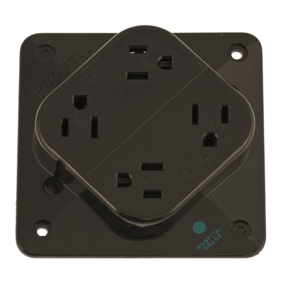
Hubbell 4-PLEXTM Receptacles, Adapter Plate, and Portable Box
Wiring and Assembly Instructions
READ INSTRUCTIONS COMPLETELY PRIOR TO INSTALLATION.
G E N E R A L W I R I N G I N F O R M A T I O N :
Notice: For installation only by a qualilied electri-
cian in accordance with the National Electrical
Code9 Canadian Electrical Code, and local code
requirements, and the following instructions.
.
Caution: Risk of electric shock. Disconnect
power before installing. Never wire energized
electrical components.
A t t e n t i o n : R i s q u e d e c h o c k e l e c t r i q u e .
D6branchef le circuit avant I'installation. Ne ia-
mais faire les connections sur circuit vivant.
Caution: Use with copper conductors only.
Attention: Employer uniquement ave fil de
c u l v e r .
Binding head terminal screws accept up to #12
AWG solid or stranded conductors.
D o n o t u s e t i n n e d ' c o n d u c t o r s .
Refer to NECoTable 400-5 or CEC Table 12 lor
ampacity of flexible cords. Use ampacities from
the 60oC column. Portable box accepts cord
ranges 16/3SJ to 12l3SO.
.
Reler to NECOTable 310-16 or CEC Table 2 tor
ampacity ot insulated conductors. Use conduc-
tors with insulation rated 90oC or higher having
sufficient ampacity in accordance with the 60oC
c o l u m n .
NOTE TO INSTALLER: lnstructions should be left
with end user tor tuture reference.
SURGE SUPPRESSOR RECEPTACLE
Refer to general wiring inlormation (above and be-
low).
Connect this device only to 1 25 VAC max. grounded
branch circuit with listed or certilied over-current
orotectlon rateclz$Fmax. (U.S.) or attffibff
current rating (Canada). Inadvertent connection to
a higher voltage will damage the device. Oiscon-
nection of neutral conductor while circuit is ener-
gized on a 1251250 VAC service could produce a
damaging higher voltage.
CAUTION: RISK OF ELECTRIC SHOCK. This
device is intended for installation on a SINGLE
branch circuit (2-wire plus ground) only" DO
NOT separately wire the outlets of this device to
a multFwire branch circuit (3-wire plug ground).
ATTENTION: RISQUE DE CHOC ELECTRIOUE.
Ce dispositil est pour un installation sur un
courant SIMPLE (2 lils et mise A la terre) seule-
ment. NE pas brancher s6parement les prises
du dispositif sur un A circuit multiple branche'
ments (3 fils et mise a la terre).
This device may be wired as a feed-thru unit t0
protect additional outlets on tf'e same ci::rt
O P E R A T I O N
GREEN-Light Emittin Diode (LED)
"ON" indicates
that power is on and surge protection is tunctioning.
A faint glow of ihe red LED is noticeable and indi-
cates LED is lunctioning and is in a standby condi-
tion.
When the green LED light goes oui and the red LED
is BRIGHTLY LlT, the receptacle is no longer able
to provide surge protection because of damage
caused by large transient surges beyond the recep-
tacle's rating. The receptacle will continue to func-
tion without surge protection. Replace the entire
unit immediately to restore surge protection.
This device is not a lightning arrestor and lightning
may damage the unit.
NOTICE
Do not hot wire surge suppressor receptacle -
doing so will damage the unit and void warranty.
Turn off power to outlet by removing fuse or turning
ofl circuit breaker. lf an existing duplex receptacle
is being replaced, shut oft power to receptacle,
confirm that both outlets are not powered by using
a test lamp. lf both outlets are not powered' pro-
ceed to Step 1. lf power is present in eithet outlet,
the existing outlet was split-wired. Surge suppres-
sor receotacles cannol be used to replace a split-
wire receotacle.
Adapter Plate
(2) Knockouts for op'
tional 4 screw mount-
ing to adapter plate.
one receptacle), consult a qualified electrician
for prop€r wiring and installation. Should this
situation exist, do not anempt installation with-
out a oualified electrician.
4. 4-PLEX lsolated Ground lnstallations: The 4-
PLEX may be installed as an
"lsolated
ground" device it a separate insulated equip-
ment grounding wire has been installed trom
the ground bus at service entrance. When in-
stalled this way, the metallic raceway and de-
vice box MUST Oe grounded to the normal
building ground system and the isolated
ground wire MUST be connected to the receP
tacte. Tne "lsolated ground" label MUST be
placed on the front surface of the 4-PLEX
where visible after installation for identifica-
tion required by the National Electrical Codeo
Section 410-56(c).
4 - P L E X
R E C E P T A C L E
' SN€AK OFF.TAES
TERMINAL SCREWS
EACK V|EW
STRIP GAUGE
t Not accesible or removeable on 4-PLEX receptacles with surge suppression.
@
Anchor Hole
1. Mount adapter date to box using (2) *32 x7l8
inch flat head screu6. Position flange side
facing box and pull cable ftrougilt opening in
adapter Plate.
2. Strip insulation on individual conductors 3/4
inch and wire each to proper terminal; black
conductor to brass screw, white conductor to
silver screw, green or bare conductor to
green grounding screw. Anchor conductor in
anchor hole provided and wrap in a counter-
clockwise direction. For larger size conduc-
tors, form loop and place under head of termi-
nal screw. Tighten terminal screws 1G12
pound-inches (1.2 - 1,4 N.m) in a clockwise
direction.
A grounding ftilail is provid€d to ground recepta-
cle to a metallic box where no grounding con-
ductor is available. (See Step 4 for isolated
Ground installations.)
lf box contains additional conductors to feed
other recegtacles on the same circuit, use re-
maining terminal screws to connect the con-
ductors. Follow the color code designations
above. Consult a qualified electrician if you
have any questions concerning the installa-
tion of this device: Take extra caution that
there are no loose strands.
3. 4-PLEX without Surge Suppression: Two
break ofl trabs are grovided for split circuit wir
ing. A and B circuit identitication is molded
into face of recegtacle.
lf you control a receptacle or portion of the fe
ceptacle lrom a wall switch, or if the recepta-
cle has split circuit wiring (two circuits feeding
Advertisement


Need help?
Do you have a question about the 4-PLEX and is the answer not in the manual?
Questions and answers