Table of Contents
Advertisement
OPERATION AND INSTALLATION
ELECTRONICALLY CONTROLLED INSTANTANEOUS WATER HEATER
» CE/CES/CERO 12 KW
» CE/CES/CERO 15 KW
» CE/CES/CERO 18 KW
» CE/CES/CERO 24 KW
» CE/CES/CERO 27 KW
» CE/CES/CERO 36 KW
» CE/CES/CERO 48 KW
» CE/CES/CERO 54 KW
» CE/CES
60 KW
» CE/CES/CERO 72 KW
» CE/CES/CERO 81 KW
» CE/CES/CERO 90 KW
» CE/CES/CERO 108 KW
» CE/CES
120 KW
» CE/CES/CERO 144 KW
Conforms to ANSI/UL Std. 499
Certified to CAN/CSA Std. C22.2 No.88
Advertisement
Table of Contents

Related Manuals for STIEBEL ELTRON CE Series


Summary of Contents for STIEBEL ELTRON CE Series
- Page 1 OPERATION AND INSTALLATION ELECTRONICALLY CONTROLLED INSTANTANEOUS WATER HEATER » CE/CES/CERO 12 KW » CE/CES/CERO 15 KW » CE/CES/CERO 18 KW » CE/CES/CERO 24 KW » CE/CES/CERO 27 KW » CE/CES/CERO 36 KW » CE/CES/CERO 48 KW » CE/CES/CERO 54 KW »...
-
Page 2: Table Of Contents
Maintenance ____________________________________________________ 7 sages that follow this symbol to avoid possible injury or death. Technical data __________________________________________________ 8 10.1 Technical data - CE series _________________________________________ 8 Safety information 10.2 Technical data - CES series _______________________________________ 9 10.3 Technical data - CERO series ____________________________________10 1.1.1 Structure of safety information... -
Page 3: Other Symbols In This Document
OPERATION SAFETY 1.1.3 Keywords Damage to the water heater and the environment The water heater must be installed by a licensed electrician KEYWORD Description and plumber. The installation must comply with all national, DANGER If this information is not observed, it will result in serious state and local plumbing and electric codes. -
Page 4: Functional Characteristics
OPERATION FUNCTIONAL CHARACTERISTICS Functional characteristics CE/CES/CERO models are three-phase instantaneous electric water heaters, intended for commercial use, permanently wired in Delta or Wye configuration. Each series has models with power output ranging from 12–144 kW. CE models feature adjustable temperature output with a range of 90–185 °F (32–85 °C), user-adjustable in one degree increments (°F or °C) via a push button switch (13). -
Page 5: Troubleshooting
OPERATION TROUBLESHOOTING Fault table possibility of dry firing. Each element circuit is individually fused. The fuses are located in the fuse box (7). Symptom Possible cause Action In order to avoid latent heat buildup, the unit has an electronically No hot water (A) Circuit breakers off Turn circuit breakers on controlled delay timer that delays the activation of the heating ele-... -
Page 6: Mounting The Water Heater
INSTALLATION MOUNTING THE WATER HEATER 5.1.2 Mounting screw positions INSTALLATION Mounting the water heater CAUTION: Injury Hot water outlet pipes leaving unit can be hot to the touch. Insulation must be used for hot water pipes below 36˝ (0.9 m) due to burn risk to children. NOTICE: This unit should not be installed in a location where it may be exposed to temperatures less than... -
Page 7: Leakage Check
Stiebel Eltron water heaters are designed for a very long service life. Actual life expectancy depends on water quality and use. To ensure Feed the wire through the knockout (A) using a Romex clamp consistent water flow, remove scale build up on the faucet or any... -
Page 8: Technical Data
INSTALLATION TECHNICAL DATA 10. Technical data 10.1 Technical data - CE series Item Number Voltage Full Load 3P Breaker No. of Pipe Standard 3-phase Amp Draw Size (A) Elements Size Enclosure Size (inches) Excluding fittings (W x H x D in inches) -
Page 9: Technical Data - Ces Series
INSTALLATION TECHNICAL DATA 10.2 Technical data - CES series Item Number Voltage Full Load 3P Breaker No. of Pipe Standard 3-phase Amp Draw Size (A) Elements Size Enclosure Size (inches) Excluding fittings (W x H x D in inches) CES 12 KW CES-012-208D 11.27 31.27... -
Page 10: Technical Data - Cero Series
INSTALLATION TECHNICAL DATA 10.3 Technical data - CERO series Item Number Voltage Full Load 3P Breaker No. of Pipe Standard 3-phase Amp Draw Size (A) Elements Size Enclosure Size (inches) Excluding fittings (W x H x D in inches) CERO 12 KW CERO-012-208D 208 10.15 28.17... -
Page 11: Dimension Drawings
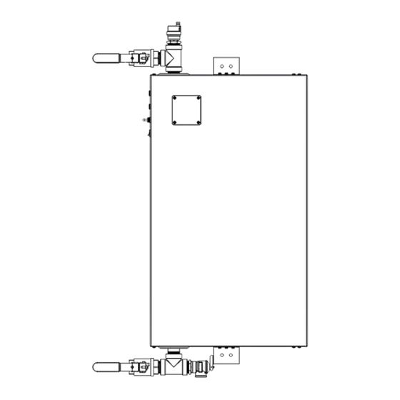
INSTALLATION TECHNICAL DATA 10.4 Dimension drawings 10.4.1 CE/CES/CERO 12–18, NEMA 3 enclosure Hot outlet Cold inlet Capacity No. of Elements 12–18 ˝ ˝ ˝ ˝ 2˝ 10.4.2 CE/CES/CERO 12–36, NEMA 4/4X enclosure Hot outlet Cold inlet Capacity No. of Elements 12–18 ˝... - Page 12 INSTALLATION TECHNICAL DATA 10.4.3 CE/CES/CERO 24–36, NEMA 3 enclosure Hot outlet Cold inlet Capacity No. of Elements 24–36 ˝ 9 ¼˝ ˝ ˝ 3˝ 10.4.4 CE/CES/CERO 48–72, NEMA 3 enclosure Hot outlet Cold inlet Capacity No. of Elements 48–72 ˝ 9 ¼˝...
- Page 13 INSTALLATION TECHNICAL DATA 10.4.5 CE/CES/CERO 81–144, NEMA 3 enclosure / CE/CES/CERO 48–144, NEMA 4/4X enclosure Hot outlet Cold inlet Capacity No. of Elements 48–72 ˝ ˝ 24˝ 48˝ 4˝ ˝ ˝ 81–108 ˝ ˝ 24˝ 48˝ 4˝ 37 ¾˝ 32 ¼˝ 120–144 ˝...
-
Page 14: Wiring Diagrams
INSTALLATION TECHNICAL DATA 10.5 Wiring diagrams 10.5.1 CE/CES/CERO 12–18, 208 V & 240 V Delta wiring diagram This diagram is valid for: CE/CES/CERO 12 208/240 V, CE/CES/CERO 15 208/240 V, CE/CES/CERO 18 208/240 V HX Flow Layout Delta Configuration Main terminal block Low pressure switch Thermistor R1-R3... - Page 15 INSTALLATION TECHNICAL DATA 10.5.2 CE/CES/CERO 12–18 400 & 480 V Wye wiring diagram This diagram is valid for: CE/CES/CERO 12 400/480 V Wye, CE/CES/CERO 15 400/480 V Wye, & CE/CES/CERO 18 400/480 V Wye HX Flow Layout Wye Configuration Low pressure switch Main terminal block Thermistor R1-R3...
- Page 16 INSTALLATION TECHNICAL DATA 10.5.3 CE/CES/CERO 24–36, 208 V & 240 V Delta wiring diagram This diagram is valid for: CE/CES/CERO 24 208/240 V, CE/CES/CERO 27 208/240 V, & CE/CES/CERO 36 208/240 V HX Flow Layout Delta Configuration Main terminal block Low pressure switch Thermistor R1-R6...
- Page 17 INSTALLATION TECHNICAL DATA 10.5.4 CE/CES/CERO 24–36, 400 V & 480 V Delta wiring diagram This diagram is valid for: CE/CES/CERO 24 400/480 V, CE/CES 27 400/480 V, CERO 27 480 V, & CE/CES/CERO 36 400/480 V HX Flow Layout Delta Configuration Fuse block R1-R6 Resistance element...
- Page 18 INSTALLATION TECHNICAL DATA 10.5.5 CE/CES/CERO 24, CE/CES/CERO 36 575 V Delta wiring diagram This diagram is valid for: CE/CES/CERO 24 575 V, & CE/CES/CERO 36 575 V HX Flow Layout Delta Configuration R1-R6 Resistance element Fuse block Thermostat block 1 Thermistor Element block 1 F1-F3...
- Page 19 INSTALLATION TECHNICAL DATA 10.5.6 CE/CES/CERO 48–72, 208 V & 240 V Delta wiring diagram This diagram is valid for: CE/CES 48 208/240 V, CERO 48 240 V, CE/CES 54 208/240 V, CERO 54 240 V, CE/CES 60 208/240 V, CE/CES 72 208/240 V, & CERO 72 240 V Delta Configuration HX Flow Layout R1-R12...
- Page 20 INSTALLATION TECHNICAL DATA 10.5.7 CE/CES/CERO 48–72, 400 V & 480 V Delta wiring diagram This diagram is valid for: CE/CES/CERO 48 400/480 V, CE/CES 54 400/480 V, CERO 54 480 V, CE/CES 60 400/480V, CE/CES 72 480 V, & CERO 72 400/480 V HX Flow Layout Delta Configuration R1-R12...
- Page 21 INSTALLATION TECHNICAL DATA 10.5.8 CE/CES/CERO 48, CE/CES/CERO 72 575 V Delta wiring diagram This diagram is valid for: CE/CES/CERO 48 575 V, CE/CES/CERO 72 575 V HX Flow Layout Delta Configuration R1-R12 Resistance element Fuse block Thermostat block 1 Thermistor Element block 1 F1-F6 Fuse...
- Page 22 INSTALLATION TECHNICAL DATA 10.5.9 CE/CES/CERO 120, CE/CES/CERO 144 400 V & 480 V Delta wiring diagram (page 1) This diagram is valid for: CE/CES/CERO 120 400/480 V, CE/CES/CERO 144 400/480 V HX Flow Layout Element block 2 Thermostat block 2 Thermistor 1 T1-T24 Thermostat...
- Page 23 INSTALLATION TECHNICAL DATA 10.5.10 CE/CES/CERO 120, CE/CES/CERO 144 400 V & 480 V Delta wiring diagram (page 2) This diagram is valid for: CE/CES/CERO 120 400/480 V, CE/CES/CERO 144 400/480 V WWW.STIEBEL-ELTRON-USA.COM CE CES CERO SERIES|...
- Page 24 INSTALLATION TECHNICAL DATA 10.5.11 CE/CES/CERO 144 575 V Delta wiring diagram (page 1) This diagram is valid for: CE/CES/CERO 144 575 V HX Flow Layout Element block 2 Thermostat block 2 Triac block Thermistor 1 T1-T24 Thermostat Thermistor 2 TR1-TR12 Triac F1-F12 Fuse...
- Page 25 INSTALLATION TECHNICAL DATA 10.5.12 CE/CES/CERO 144 575 V Delta wiring diagram (page 2) This diagram is valid for: CE/CES/CERO 144 575 V WWW.STIEBEL-ELTRON-USA.COM CE CES CERO SERIES|...
-
Page 26: Ce/Ces/Cero Temperature Rise
INSTALLATION TECHNICAL DATA 10.6 CE/CES/CERO Temperature rise Power Flow Rate Temperature Rise Output Gallons/Min. of Model Gallons/Hr. 20°F 30°F 40°F 50°F 60°F 70°F 80°F 90°F 100°F 110°F 120°F 130°F 140°F 12 kW 15 kW 18 kW 24 kW 27 kW 36 kW 12.3 48 kW... -
Page 27: Spare Parts And Service Advice
INSTALLATION SPARE PARTS AND SERVICE ADVICE 11. Spare parts and service advice DANGER: Electrocution Before proceeding with any installation, adjustment, alteration, or service of the appliance all circuit break- er, switches servicing the appliance must be turned off. Make sure that nobody can activate the breaker in the distribution panel during your service work on the ap- pliance. - Page 28 INSTALLATION SPARE PARTS AND SERVICE ADVICE Turn on the power supply. Turn on the on/off power switch. Transformer Disconnect the heater from the power supply. Check for continuity on the fuse FLM1-1/4 to be sure the problem is not just a transformer fuse. Replace wire from the transformer distribution block.
-
Page 29: Warranty
This Warranty is valid for U.S.A. & Canada only. Warranties may Please help us to protect the environment by disposing of the vary by country. Please consult your local Stiebel Eltron Repre- packaging in accordance with the national regulations for waste sentative for the Warranty for your country. - Page 30 NOTES | CE CES CERO SERIES WWW.STIEBEL-ELTRON-USA.COM...
- Page 31 NOTES WWW.STIEBEL-ELTRON-USA.COM CE CES CERO SERIES |...
- Page 32 TANKLESS, Inc. A Stiebel Eltron Company 2060 Whitfield Park Ave. | Sarasota, FL 34243 Tel. 800.TANKLESS (800.826.5537) | Fax 941.755.6529 tanklessinc stiebel-eltron-usa.com STIEBEL ELTRON, Inc. 17 West Street | West Hatfield MA 01088 Tel. 413.247.3380 | Fax 413.247.3369 info stiebel-eltron-usa.com www.stiebel-eltron-usa.com...
Need help?
Do you have a question about the CE Series and is the answer not in the manual?
Questions and answers