Advertisement
Quick Links
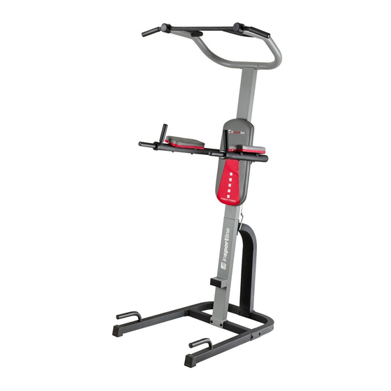
IN3948 POWER
TOWERR
CAUTION:
WARNING: Do not use this
product without a physician's
approval.
Do not let children use this
product unsupervised.
Read all instructions carefully
before using.
Tighten all bolts before using
equipment.
Leave adequate space to
exercise
CAUTION:
Maximum Weight Limit is 300
lbs.
Photo may differ from actual product
.
Advertisement

Subscribe to Our Youtube Channel
Related Manuals for Insportline IN3948


Summary of Contents for Insportline IN3948
- Page 1 IN3948 POWER TOWERR CAUTION: WARNING: Do not use this product without a physician’s approval. Do not let children use this product unsupervised. Read all instructions carefully before using. Tighten all bolts before using equipment. Leave adequate space to exercise CAUTION: Maximum Weight Limit is 300 lbs.
-
Page 2: Before Beginning Assembly
POWER TOWER Owner’ s Manual BEFORE BEGINNING ASSEMBLY CAUTION: Maximum Weight Limit is 300 lbs. Take a few moments to familiarize yourself with the specific parts and hardware included with your product. Make sure all the parts and hardware are included in the carton and examine them for any damage that may have occurred in transport. -
Page 3: Parts Listing
Parts Listing... -
Page 4: Exploded View
Exploded View... - Page 5 Baseframe Assembly- Step 1 Connect Left Lower Baseframe (1) to Right Lower Baseframe (2) using Lower Cross Bar Support (3) and secure with 4 Bolts (16) , 2 Metal Support Plates( 4), 4 Washers (17) and 4 Nuts (18). Place End Caps (15) on ends of Baseframe 1 &...
- Page 6 Mainframe Assembly –Step 2 inframe Assembly -Step Mainframe Assembly ( cont) –Step 3 Connect Lower Section (5) of Mainframe Support to Lower Cross Bar Support (3) using 2 Bolts (19), 2 Washers (17) and 2 Nuts (18)
- Page 7 NOTE: Tighten All Bolts At This Time Mainframe Assembly ( cont) –Step 3 Connect Rear Support Frame (6) to Lower Baseframe sections (1&2), using 2 Bolts (19), 2 Washers (17) and 2 Nuts (18) Connect Upper Section (7) of Mainframe Support to Lower Mainframe Support (5) using 4 Threaded...
- Page 8 NOTE: Tighten All Bolts At This Time Upper Pull Up Frame Assembly- Step 4 Connect Handlebars (10 &11) to Upper Pull Up Frame Assembly (9) using Bolts (16) and Washers (21). Connect Handlebars to Upper Frame Assembly using Screws (23) and washers (22). Place Round Caps (24) over End of Handle Assembly.
- Page 9 NOTE: Tighten All Bolts At This Time Upper Frame Assembly (Cont.)- Step 5 Connect completed Upper Handle Assembly to Mainframe Assembly using 4 Screws (20) and 4 Washers (17)
- Page 10 NOTE: Tighten All Bolts At This Time Vertical Knee Raise / Dip Assembly - Step 6 Connect Vertical Knee Raise/Dip Assembly (8) to completed Mainframe Assembly (5/7) using Bolt ( 25), 1 Washer (17) and Nut (18)
- Page 11 NOTE: Tighten All Bolts At This Time Arm Pad Assembly- Step 7 Connect Arm Rest Pads (12) to Vertical Knee Raise/Dip Assembly (8) using 4 Screws (26) and 4 Washers (22)
- Page 12 NOTE: Tighten All Bolts At This Time Upper Frame Assembly (Cont.)- Step 8 Install Backrest Pad (13) Upper Mainframe (7) using 2 Screws (26) and 2 Washers (27). Note: Self Tapping Screw (14) is used to secure Vertical Knee Raise (8) in Upper Position to Accommodate Pull...
- Page 13 NOTE: Tighten All Bolts At This Time Vertical Knee Raise/Dip Assembly Adjustment Step 9 Vertical Knee Raise/Dip Assembly (8) can be adjusted Up or Down using Pin (14)
-
Page 14: Final Assembly
NOTE: Tighten All Bolts At This Time Final Assembly 300 Lb.Weight Capacity CAUTION: MAKE SURE ALL NUTS, OLTS & SCREWS ARECOMPLETELY TIGHTENED BEFORE USE...
Need help?
Do you have a question about the IN3948 and is the answer not in the manual?
Questions and answers