Table of Contents
Advertisement
Operator's Manual
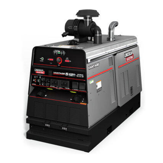
Vantage
Register your machine:
www.lincolnelectric.com/register
Authorized Service and Distributor Locator:
www.lincolnelectric.com/locator
Save for future reference
Date Purchased
Code: (ex: 10859)
Serial: (ex: U1060512345)
IM10540
| Issue D ate Jan-20
© Lincoln Global, Inc. All Rights Reserved.
549X
®
For use with machines having Code Numbers:
12904, 12905
Need Help? Call 1.888.935.3877
to talk to a Service Representative
Hours of Operation:
8:00 AM to 6:00 PM (ET) Mon. thru Fri.
After hours?
Use "Ask the Experts" at lincolnelectric.com
A Lincoln Service Representative will contact you
no later than the following business day.
For Service outside the USA:
Email: globalservice@lincolnelectric.com
Advertisement
Table of Contents

Subscribe to Our Youtube Channel
Related Manuals for Lincoln Electric Vantage 549X


Summary of Contents for Lincoln Electric Vantage 549X
- Page 1 Operator’s Manual Vantage 549X ® For use with machines having Code Numbers: 12904, 12905 Need Help? Call 1.888.935.3877 Register your machine: to talk to a Service Representative www.lincolnelectric.com/register Authorized Service and Distributor Locator: Hours of Operation: www.lincolnelectric.com/locator 8:00 AM to 6:00 PM (ET) Mon. thru Fri. Save for future reference After hours? Use “Ask the Experts”...
- Page 2 THANK YOU FOR SELECTING A QUALITY PRODUCT BY KEEP YOUR HEAD OUT OF THE FUMES. DON’T get too close to the arc. LINCOLN ELEC TRIC. Use corrective lenses if necessary to stay a reasonable distance away from the arc. READ and obey the Safety Data PLEASE EXAMINE CARTON AND EQUIPMENT FOR Sheet (SDS) and the warning label DAMAGE IMMEDIATELY...
- Page 3 W117.2. A Free copy of “Arc Welding Safety” booklet E205 is available from the Lincoln Electric Company, 22801 2.d. All welders should use the following procedures in order to St. Clair Avenue, Cleveland, Ohio 44117-1199.
- Page 4 SAFETY ELECTRIC SHOCK ARC RAYS CAN BURN. CAN KILL. 3.a. The electrode and work (or ground) circuits are 4.a. Use a shield with the proper filter and cover plates to protect your electrically “hot” when the welder is on. Do eyes from sparks and the rays of the arc when welding or not touch these “hot”...
- Page 5 SAFETY WELDING AND CUTTING CYLINDER MAY EXPLODE IF SPARKS CAN CAUSE DAMAGED. FIRE OR EXPLOSION. 7.a. Use only compressed gas cylinders containing the correct shielding gas for the process used 6.a. Remove fire hazards from the welding area. If and properly operating regulators designed for this is not possible, cover them to prevent the welding sparks the gas and pressure used.
- Page 6 TABLE OF CONTENTS...
-
Page 7: Table Of Contents
TABLE OF CONTENTS CV-WIRE MODE ...............................B-12 ARC GOUGING MODE ...............................B-12 ARCLINK MODE ...............................B-12 PULSE WELDING..............................B-13 CROSSLINC ................................B-14 PARALLELING ................................B-14 AUXILIARY POWER OPERATION..........................B-15 SIMULTANEOUS WELDING AND AUXILIARY POWER LOADS ..................B-15 TYPICAL FUEL CONSUMPTION ..........................B-16 ACCESSORIES ..............................SECTION C CROSSLINC ACCESSORIES ............................C-1 GENERAL ACCESSORIES............................C-1 TIG ACCESSORIES ..............................C-1 WIRE FEEDERS &... - Page 8 ® VANTAGE 549X GRAPHIC SYMBOLS The following graphics appear on the machine or in the manual. Warning or Caution Engine Downhill Pipe welding Instructions Remote Fumes and Gases Oil Pressure Arc Control Explosion Engine Temperature Pulse Arc Rays Engine Hours Voltmeter Polarity Moving Parts Fuel...
- Page 9 ® VANTAGE 549X INSTALLATION OUTPUT @ 104°F(40°C) - WELD ER AND GENERATOR GENERAL DESCRIPTION Welding Mode Output Range ® The Vantage 549X is a diesel engine-driven welding power source. The machine uses a brush type alternating current CC-Stick 30-575 Amps generator for DC multi-purpose welding, for 120/240 VAC single Downhill Pipe (CC) 40-350 Amps...
- Page 10 ® VANTAGE 549X INSTALLATION INSTALLATION FIGURE A.1 ON / OFF VDR SWITCH SAFETY PRECAUTIONS WARNING Do not attempt to use this equipment until you have thoroughly read all operating and maintenance manuals supplied with your machine. They include important safety precautions, detailed engine starting, operating and maintenance instructions and parts lists.
- Page 11 ® VANTAGE 549X INSTALLATION STORING HIGH ALTITUDE OPERATION 1. Store the machine in a cool, dry place when it is not in use. At higher altitudes, output derating may be necessary. For Protect it from dust and dirt. Keep it where it can’t be maximum rating, derate the welder output in accordance with the accidentally damaged from construction activities, moving guidelines in Table A.1 below for this engine model from the...
- Page 12 ® VANTAGE 549X INSTALLATION WARNING TOWING Use a recommended trailer for use with this equipment for road, • Stop engine and allow to cool before fueling. in-plant and yard towing by a vehicle . If the user adapts a non- Lincoln trailer, they must assume responsibility that the method of •...
- Page 13 ® VANTAGE 549X INSTALLATION SPARK ARRESTOR BATTERY CONNECTION Some federal, state or local laws may require that gasoline or diesel engines be equipped with exhaust spark arrestors when CAUTION they are operated in certain locations where unarrested sparks may present a fire hazard. Use caution as the electrolyte is a strong acid that can burn The DOC (Diesel Oxidation Catalyst) unit included with this welder skin and damage eyes.
- Page 14 ® VANTAGE 549X INSTALLATION MACHINE GROUNDING The 120 VAC auxiliary power receptacles should only be used with three wire grounded type plugs or approved double insulated tools Because this portable engine driven welder creates its own power, with two wire plugs. The current rating of any plug used with the it is not necessary to connect its frame to an earth ground, unless system must be at least equal to the current capacity of the the machine is connected to premises wiring (home, shop, etc.).
- Page 15 ® VANTAGE 549X INSTALLATION STANDBY POWER CONNECTIONS 2. Take necessary steps to assure load is limited to the capacity ® of the Vantage 549X by installing a 50 amp, 240 VAC double ® The Vantage 549X is suitable for temporary, standby or pole circuit breaker.
- Page 16 ® VANTAGE 549X INSTALLATION CAUTION WELDING OUTPUT CABLES • Loose connections will cause the output terminals to With the engine off, route the electrode and work cables through overheat. The terminals may eventually melt. the strain relief bracket provided on the front of the base and connect to the terminals provided.
- Page 17 ® VANTAGE 549X INSTALLATION CABLE INDUCTANCE AND ITS EFFECTS ON CONTROL CABLE CONNECTIONS WELDING General Guidelines Excessive cable inductance will cause the welding performance to Genuine Lincoln control cables should be used at all times (except degrade. There are several factors that contribute to the overall where noted otherwise).
- Page 18 VANTAGE 549X INSTALLATION ® REMOTE CONTROL CONNECTIONS WELDING TERMINALS The Vantage ® 549X is equipped with a 12-pin and a 14-pin The Vantage ® 549X is equipped with a toggle switch for selecting connector. To enable remote control capabilities, the "hot"...
- Page 19 ® VANTAGE 549X INSTALLATION For electrode negative, connect the electrode cable “-” terminal of the welder and work cable to the “+” terminal of ACCESSORY CONNECTION DIAGRAMS the welder. Installation diagrams for common setups are included on the following pages. WARNING •...
- Page 20 ® VANTAGE 549X INSTALLATION CROSSLINC SETUP CV FIGURE A.7 Item Desc. ® Machine Vantage 549X K3534-2 Feeder LN-25X w/TVT K4267-2 ® ® K126 PRO Innershield 350A FCAW-SS Welding K126-12 Gun 15 ft 1/16-5/64 Weld Power Cable - Lug to Work Lug (3/0, 600A, 60%) - 35 K1842-35 Cable...
- Page 21 ® VANTAGE 549X INSTALLATION DUAL ARC SETUP Item Desc. ® FIGURE A.9 Machine Vantage 549X K3534-2 Feeder LN-25X w/TVT K4267-2 ® ® K126 PRO Innershield 350A FCAW-SS Welding K126-12 Gun 15 ft 1/16-5/64 Weld Power Cable - Lug to Work Lug (3/0, 600A, 60%) - 35 K1842-35 Cable...
- Page 22 ® VANTAGE 549X INSTALLATION TIG MODULE Item Desc. Machine Vantage 549X K3534-2 Accessory TIG Module K930-2 Control Cable 9 - 14 Pin Cable K936-1 FIGURE A.10 Torch PTA-26 (25 ft) K1783-4 Foot Pedal Foot Amptrol (25 ft) K870 Electrode Cable...
- Page 23 ® VANTAGE 549X OPERATION OPERATION RECOMMENDED APPLICATIONS ® WELDER - The Vantage 549X provides excellent constant SAFETY INSTRUCTIONS current DC welding output for stick (SMAW) and TIG (GTAW) weld- Read and understand this entire section ® ing. The Vantage 549X also provides excellent constant voltage before operating your machine.
- Page 24 ® VANTAGE 549X OPERATION ADD FUEL STARTING THE ENGINE 1. Remove all plugs connected to the AC power receptacles. WARNING 2. Set RUN / STOP / IDLE switch to AUTO IDLE / RUN position. DIESEL FUEL can cause fire. 3. Press START / GLOW PLUG switch and hold until machine •...
- Page 25 ® VANTAGE 549X OPERATION CONTROLS AND SETTINGS All welder and engine controls are located on the case front panel. Refer to Figure B.1 and the explanations that follow. 1D. FUEL LEVEL - Displays the level of diesel fuel in the fuel tank. SYSTEM CONTROLS The operator must watch the fuel level closely to prevent 1.
- Page 26 ® VANTAGE 549X OPERATION 3. CROSSLINC INDICATOR LIGHT - When a CrossLinc 8. 42V / 120V WIRE FEEDER VOLTAGE SWITCH enabled device is connected with the machine using the stan- Toggles output of 14-pin connector to voltage requirement of dard weld power cable and the device's sense lead is attached wire feeder.
- Page 27 ® VANTAGE 549X OPERATION 11. START / GLOW PLUG SWITCH - Energizes the 16. HIDDEN MENU BUTTON - The hidden setup menu can starter motor to crank the engine. With the engine RUN / be accessed any time the machine is on with the engine run- STOP / IDLE switch in the "RUN"...
- Page 28 VANTAGE 549X OPERATION ® 26. 240 VAC THREE PHASE RECEPTACLE - This is a 32. DIAGNOSTIC PLUG - This is used by eld service 240 VAC (15-50R) receptacle that provides 240 VAC three shops to connect and troubleshoot engine error codes, found on the rewall inside the machine.
- Page 29 ® VANTAGE 549X OPERATION FIGURE B.9 HIDDEN SETUP MENU FUNCTIONS HOT START CONTROL Hot start can be set based off weld mode. Non-applicable weld modes will not display hot start. The left display will show “Hot” and “Strt” alternately at 0.5 second intervals.
- Page 30 ® VANTAGE 549X OPERATION RESET BACK TO DEFAULT SETTINGS TEST MODES FOR GRID LOAD TESTING Pressing and holding the hidden reset push button for 5 seconds The left display will show “tESt” and “LoAd” alternately at 0.5 will cause certain stored values to be reset to defaults. The stored second intervals.
- Page 31 They include important safety NOTE: The duty cycles for the IEC rated output and max output are precautions, detailed engine starting, operating and listed on the front nameplate of the Vantage 549X. maintenance instructions and parts lists. ELECTRIC SHOCK can kill.
- Page 32 ® VANTAGE 549X OPERATION WELDER OPERATION HIGH FREQUENCY TIG OPTIONS CC-STICK MODE In general the ‘Touch Start’ feature avoids tungsten contamination ® The Vantage 549X can be used with a broad range of DC stick without the use of a high frequency unit. If the use of a high electrodes.
- Page 33 ® VANTAGE 549X OPERATION SETTINGS WHEN USING THE K930-2 TIG MODULE • Set the WELD MODE switch to the TOUCH START TIG setting. • Set the RUN / STOP / IDLE switch to the AUTO IDLE / RUN position. • Set the WELDING TERMINALS switch to the REMOTELY CONTROLLED position.
-
Page 34: Cv-Wire Mode
® VANTAGE 549X OPERATION CV-WIRE MODE NOTE: If desired the CV-WIRE mode can be used for arc gouging applications. ® Connect a wire feeder to the Vantage 549X and set welder controls according to the instructions listed earlier in this section. ®... -
Page 35: Pulse Welding
® VANTAGE 549X OPERATION PULSE WELDING UltimArc™ Control Pulse welding procedures are set by controlling an overall “arc UltimArc™ Control adjusts the focus or shape of the arc. length” variable. When pulse welding, the arc voltage is highly UltimArc™ Control is adjustable from -10.0 to +10.0 with a dependent upon the waveform. -
Page 36: Crosslinc
® VANTAGE 549X OPERATION TABLE B.4 The following modes can be accessed via an ArcLink feeder: Synergic CV Modes Metal Dia. Steel Stainless Core Flux Core Aluminum Argon Argon Argon inches CO2 Tri-Mix Argon Mix CO2 4043 5356 .030 • •... -
Page 37: Auxiliary Power Operation
The current rating of any plug used with the system must be at least equal to the current capacity of the associated receptacle. TABLE B.5 VANTAGE 549X SIMULTANEOUS WELDING AND POWER LOADS WELD 1 PHASE 3 PHASE... -
Page 38: Typical Fuel Consumption
VANTAGE 549X OPERATION ® TYPICAL FUEL CONSUMPTION Refer to Table B.7 for typical fuel consumption of the Vantage ® 549X Engine for various operating scenarios. TABLE B.7 (Deutz TD2.9L4) Fuel Consumption RUN TIME (HRS.) GAL. / HR. L / HR. WITH FULL TANK* High Idle... -
Page 39: Accessories
VANTAGE 549X ACCESSORIES ® ACCESSORIES Air Filter Guard Kit Placed around the air lter to provide additional protection from incidental damage. CROSSLINC ACCESSORIES Order: K4698-1 LN-25X True Voltage Technology (TVT) is now included with the LN-25X Deutz Engine Service Kit ®... -
Page 40: Wire Feeders & Guns
® VANTAGE 549X ACCESSORIES TIG Module CABLE ACCESSORIES ® Supplies high frequency for superior starting, contactor control, Tweco Adaptors remote control capability, and a gas valve for AC or DC TIG Allows for quick cable changeovers on the jobsite. welding. Order: K2487-1 Stud to Tweco Female Adapter –... -
Page 41: Maintenance
® VANTAGE 549X MAINTENANCE MAINTENANCE ROUTINE AND PERIODIC MAINTENANCE DAILY SAFETY PRECAUTIONS • Check the engine oil level. READ AND UNDERSTAND ENTIRE SECTION BEFORE • Refill the fuel tank to minimize moisture condensation in the OPERATING MACHINE. tank. • Open the water drain valve located on the bottom of the water WARNING separator element 1 or 2 turns and allow to drain into a container suitable for diesel fuel for 2 to 3 seconds. -
Page 42: Engine Maintenance
VANTAGE 549X MAINTENANCE ® ENGINE MAINTENANCE Refer to the SERVICE PLAN section of the Engine Operator’s Manual for the recommended maintenance schedule of the following: a) Engine Oil and Filter b) Air Cleaner c) Fuel Filter and Delivery System d) Alternator Belt e) Battery f) Cooling System Refer to Table D.1 at the end of this section for various engine... - Page 43 ® VANTAGE 549X MAINTENANCE Service Instructions Service Instructions Single- and Two-Stage Engine Air Cleaners Single- and Two-Stage Engine Air Cleaners Inspect the New Filter for Damage Inspect the New Filter for Damage Remove the Filter Remove the Filter Inspect the new filter carefully, paying attention to Unfasten or unlatch the the inside of the open end, which is the service cover.
-
Page 44: Fuel Filters
VANTAGE 549X MAINTENANCE ® FUEL FILTERS COOLING SYSTEM The cooling system of the Deutz engine needs to be checked and WARNING cleaned periodically. (Consult the Engine Owner's Manual for the proper procedures and frequency). When working on the fuel system Coolant needs to be added at the radiator ller neck after •... -
Page 45: Battery Handling
® VANTAGE 549X MAINTENANCE BATTERY HANDLING ENGINE OIL CHANGE Drain the engine oil while the engine is warm to assure rapid and WARNING complete draining. It is recommended that each time the oil is changed the oil filter be changed as well. GASES FROM BATTERY can •... -
Page 46: Tightening The Fan Belt
® VANTAGE 549X MAINTENANCE TIGHTENING THE FAN BELT If the fan belt is loose, the engine can overheat and the battery lose its charge. Check tightness by pressing on the belt midway between the pulleys. For tightness requirements, please refer to the Engine Owner's Manual. -
Page 47: Gfci Maintenance
® VANTAGE 549X MAINTENANCE GFCI MAINTENANCE WARNING • An electric shock can result in serious injury or death. • Always perform the GFCI test before using the generator. If the GFCI system fails the test, the machine must be repaired by an authorized service center. -
Page 48: Troubleshooting
® VANTAGE 549X TROUBLESHOOTING TROUBLESHOOTING HOW TO USE TROUBLESHOOTING GUIDE WARNING Service and Repair should only be performed by Lincoln Electric Factory Trained Personnel. Unauthorized repairs performed on this equipment may result in danger to the technician and machine operator and will invalidate your factory warranty. - Page 49 ® VANTAGE 549X TROUBLESHOOTING Observe all Safety Guidelines detailed throughout this manual PROBLEMS POSSIBLE RECOMMENDED (SYMPTOMS) CAUSE COURSE OF ACTION ENGINE PROBLEMS Major Physical or Electrical Damage . Contact your Local Lincoln is Evident. Authorized Field Service Facility. 1. Battery low. Engine will not crank 2.
- Page 50 ® VANTAGE 549X TROUBLESHOOTING Observe all Safety Guidelines detailed throughout this manual PROBLEMS POSSIBLE RECOMMENDED (SYMPTOMS) CAUSE COURSE OF ACTION FUNCTION PROBLEMS Battery does not stay charged. 1. Faulty battery. 2. Faulty engine alternator. 3. Loose or broken lead in charging circuit.
- Page 51 ® VANTAGE 549X TROUBLESHOOTING Observe all Safety Guidelines detailed throughout this manual PROBLEMS POSSIBLE RECOMMENDED (SYMPTOMS) CAUSE COURSE OF ACTION FUNCTION PROBLEMS Engine goes to low idle but does 1. Faulty Weld Control PCB or Idler not stay at low idle. relay.
- Page 52 ® VANTAGE 549X WIRING DIAGRAMS...
- Page 53 ® VANTAGE 549X DIMENSION PRINT...
- Page 54 We respond to our customers based on the best information in our possession at that time. Lincoln Electric is not in a position to warrant or guarantee such advice, and assumes no liability, with respect to such information or advice.
Need help?
Do you have a question about the Vantage 549X and is the answer not in the manual?
Questions and answers