Table of Contents
Advertisement
Quick Links
For use with machine code numbers:
Safety Depends on You
Lincoln arc welding and cutting
equipment is designed and built
with safety in mind.
However,
your
overall
safety
can
increased by proper installation
. . . and thoughtful operation on
your part.
DO NOT INSTALL,
OPERATE OR REPAIR THIS
EQUIPMENT WITHOUT READ-
ING THIS MANUAL AND THE
SAFETY PRECAUTIONS CON-
TAINED THROUGHOUT.
most importantly, think before you
act and be careful.
• Sales and Service through Subsidiaries and Distributors Worldwide •
Cleveland, Ohio 44117-1199 U.S.A. TEL: 216.481.8100 FAX: 216.486.1751 WEB SITE: www.lincolnelectric.com
RETURN TO MAIN MENU
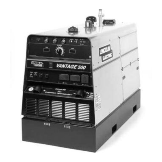
VANTAGE
be
And,
SERVICE MANUAL
• World's Leader in Welding and Cutting Products •
®
5
10995,10996,11180,11181
11415,11416,11468
Copyright © Lincoln Global Inc.
SVM178-B
April, 2011
Advertisement
Chapters
Table of Contents
Troubleshooting

Subscribe to Our Youtube Channel
Related Manuals for Lincoln Electric VANTAGE SVM178-B


Summary of Contents for Lincoln Electric VANTAGE SVM178-B
-
Page 1: Service Manual
VANTAGE For use with machine code numbers: Safety Depends on You Lincoln arc welding and cutting equipment is designed and built with safety in mind. However, your overall safety increased by proper installation . . . and thoughtful operation on your part. -
Page 2: California Proposition 65 Warnings
Miami, Florida 33135 or CSA Standard W117.2-1974. A Free copy of “Arc Welding Safety” booklet E205 is available from the Lincoln Electric Company, 22801 St. Clair Avenue, Cleveland, Ohio 44117-1199. BE SURE THAT ALL INSTALLATION, OPERATION, MAINTENANCE AND REPAIR PROCEDURES ARE PERFORMED ONLY BY QUALIFIED INDIVIDUALS. -
Page 3: Electric Shock Can Kill
ELECTRIC SHOCK can kill. 3.a. The electrode and work (or ground) circuits are electrically “hot” when the welder is on. Do not touch these “hot” parts with your bare skin or wet clothing. Wear dry, hole-free gloves to insulate hands. 3.b. - Page 4 WELDING and CUTTING SPARKS can cause fire or explosion. 6.a. Remove fire hazards from the welding area.If this is not possible, cover them to prevent the welding sparks from starting a fire. Remember that welding sparks and hot materials from welding can easily go through small cracks and openings to adjcent areas.
- Page 5 PRÉCAUTIONS DE SÛRETÉ Pour votre propre protection lire et observer toutes les instructions et les précautions de sûreté specifiques qui parraissent dans ce manuel aussi bien que les précautions de sûreté générales suiv- antes: Sûreté Pour Soudage A L’Arc 1. Protegez-vous contre la secousse électrique: a.
- Page 6 SAFETY Electromagnetic Compatibility (EMC) Conformance Introduction Installation and Use Assessment of Area VANTAGE® 500...
- Page 7 SAFETY Electromagnetic Compatibility (EMC) Methods of Reducing Emissions Mains Supply Maintenance of the Welding Equipment Welding Cables Equipotential Bonding Earthing of the Workpiece Screening and Shielding VANTAGE® 500...
- Page 8 - MASTER TABLE OF CONTENTS FOR ALL SECTIONS - Safety ................i-iv Installation .
-
Page 9: Table Of Contents
TABLE OF CONTENTS - INSTALLATION SECTION A1.1 Installation - VANTAGE® 500 Deutz F3L912 (Code 10995) Technical Specifications ............. . .A1.2 Safety Precautions . -
Page 10: Technical Specifications
A1.2 TECHNICAL SPECIFICATIONS - Vantage 500® DEUTZ (K2271-1) Make /Model Description Deutz 3 cylinder F3L 912 44HP (33 kw) Diesel Engine @ 1800 RPM Code 10995 RATED OUTPUT @ 104°F(40°C) - WELDER Duty Cycle 100% OUTPUT @ 104°F(40°C) - WELDER AND GENERATOR Height Width 42.0 in... -
Page 11: Safety Precautions
A1.3 Read this entire installation section before you start installation. SAFETY PRECAUTIONS WARNING Do not attempt to use this equipment until you have thoroughly read all operating and mainte- nance manuals supplied with your machine. They include important safety precautions, detailed engine starting, operating and instructions and parts lists. -
Page 12: Lifting
A1.4 LIFTING The Vantage® 500 lift bale should be used to lift the machine. The Vantage® 500 is shipped with the lift bale retracted. Before attempting to lift the Vantage® 500, secure the lift bale in a raised position. Secure the lift bale as follows: a. -
Page 13: Pre-Operation Engine Service
A1.5 PRE-OPERATION ENGINE SERVICE READ the engine operating and maintenance instruc- tions supplied with this machine. WARNING • Keep hands away from the engine muffler or HOT engine parts. • Stop engine and allow to cool before fueling. • Do not smoke when fueling. •... -
Page 14: Muffler Outlet Pipe
A1.6 IMPORTANT: To prevent ELECTRICAL DAMAGE WHEN: a) Installing new batteries b) Using a booster Use correct polarity — Negative Ground. The Vantage® 500 is shipped with the negative battery cable disconnected. Before you operate the machine, make sure the Engine Switch is in the OFF position and attach the disconnected cable securely to the neg- ative (-) battery terminal. -
Page 15: Welding Output Cables
A1.7 WELDING OUTPUT CABLES With the engine off, route the electrode and work cables through the strain relief bracket provided on the front of the base and connect to the terminals provided. These connections should be checked periodically and tightened if necessary. Listed in Table A1.1 are copper cable sizes recom- mended for the rated current and duty cycle. - Page 16 A1.8 1. Install the double-pole, double-throw switch between the power company meter and the premises disconnect. Switch rating must be the same as or greater than the customer’s premises disconnect and service over cur- rent protection. 2. Take necessary steps to assure load is limited to the capacity of the Vantage by installing a 50 amp, 240 VAC double-pole circuit breaker.
-
Page 17: Vantage® 500 Deutz F3L912 (Code 10995)
TABLE OF CONTENTS - OPERATION SECTION B1.1 Operation - VANTAGE® 500 Deutz F3L912 (Code 10995) Operating Instructions ..............B1.2 Safety Instructions . -
Page 18: Operating Instructions
B1.2 OPERATING INSTRUCTIONS Read and understand this entire section before oper- ating your Vantage® 500. SAFETY INSTRUCTIONS WARNING Do not attempt to use this equipment until you have thoroughly read all operating and mainte- nance manuals supplied with your machine. They include important safety precautions: detailed engine starting, operating, and instructions and parts lists. -
Page 19: Recommended Applications
B1.3 RECOMMENDED APPLICATIONS WELDER The Vantage® 500 provides excellent constant current DC welding output for stick (SMAW) and TIG welding. The Vantage® 500 also provides excellent constant voltage DC welding output for MIG (GMAW) and Innershield (FCAW) welding. GENERATOR The Vantage® 500 provides smooth 120/240 VAC out- put for auxiliary power and emergency standby power. -
Page 20: Controls And Settings
B1.4 CONTROLS AND SETTINGS All welder and engine controls are located on the case front panel. Refer to Figure B.1 and the explanations that follow. Figure B1.1 Case Front Panel Controls ENGINE CONTROLS (Items 1 through 9) 1. RUN STOP SWITCH Toggling the switch to the RUN position energizes the fuel solenoid for approximately 30 seconds. -
Page 21: Welding Controls
B1.5 6. OIL PRESSURE GAUGE The gauge displays the engine oil pressure when the engine is running. 7. ENGINE PROTECTION The yellow engine protection light remains off with proper oil pressure and under normal operating tem- peratures. If the light turns on, the engine protection system will stop the engine. -
Page 22: Auxiliary Power Controls
B1.6 13. WELDING TERMINALS SWITCH In the WELD TERMINALS ON position, the output is electrically hot all the time. In the REMOTELY CON- TROLLED position, the output is controlled by a wire feeder or amptrol device, and is electrically off until a remote switch is depressed. 14. -
Page 23: Engine Operation
B1.7 ENGINE OPERATION STARTING THE ENGINE 1. Open the engine compartment door and check that the fuel shutoff valve is in the open position (lever to be in line with the hose). 2. Check for proper oil level and coolant level. Close engine compartment door. -
Page 24: Welder Operation
B1.8 WELDER OPERATION DUTY CYCLE Duty Cycle is the the ratio of the uninterrupted on-load duration to 10 minutes. The total time period of one complete on-load and no-load cycle is 10 minutes. For example, in the case of a 60% duty cycle, load is applied continuously for 6 minutes followed by a no- load period of 4 minutes. -
Page 25: Tig Torch
B1.9 TABLE B1.2 – TYPICAL CURRENT RANGES DCEN (-) Tungsten Electrode 1%, 2% Diameter Thoriated in. (mm) Tungsten 0.010 (.25) 2-15 0.020 (.50) 5-20 0.40 (1.0) 15-80 1/16 (1.6) 70-150 3/32 (2.4) 150-250 (3.2) 250-400 5/32 (4.0) 400-500 3/16 (4.8) 500-750 (6.4) 750-1000 When used with argon gas. -
Page 26: Wire Feed (Constant Voltage) Welding
B1.10 WIRE FEED (CONSTANT VOLTAGE) WELDING Connect a wire feeder to the Vantage® 500 and set welder controls according to the instructions listed ear- lier in this section. See the operator’s manual for the wire feeder or the “Diagrams” section of this manual for connecting instructions of various Lincoln wire feed- ers. -
Page 27: Extension Cord Recommendations
B1.11 TABLE B1.3 Vantage 500 Duetz Simultaneous Welding and Power Loads Welding Output Permissible Power Watts at NEMA Voltage (Unity Power Factor) (V=.04I + 20) 0-250A/30V 350A/34V 400A/36V 450A/38V 500A/40V * Each duplex receptacle is limited to 20 amps. ** Not to exceed 50A per 120 VAC branch circuit when splitting the 240 VAC output. EXTENSION CORD RECOMMENDATIONS An extension cord can be used with the auxiliary power... - Page 28 NOTES B1.12 B1.12 VANTAGE® 500...
- Page 29 TABLE OF CONTENTS - ACCESSORIES SECTION C1.1 Accessories - VANTAGE® 500 Deutz F3L912 (Code 10995) Options/Accessories ..............C1.1 Optional Field Installed Accessories .
-
Page 30: Optional Field Installed Accessories
The use of an arc welder for pipe thawing is not approved by the CSA, nor is it recommended or supported by Lincoln Electric. ------------------------------------------------------------------------ VANTAGE® 500 C1.2... -
Page 31: Tig Welding Options
C1.3 TIG OPTIONS K1783-9 PTA-26V TIG Torch Air Cooled 200 amp torch (2 piece) equipped with valve for gas flow control. 25 ft. (7.6m) length. KP509 Magnum Parts Kit for PTA-26V TIG Torch Magnum Parts Kit provides all the torch accessories you need to start welding. - Page 32 NOTES C1.4 C1.4 VANTAGE® 500...
- Page 33 TABLE OF CONTENTS - MAINTENANCE SECTION D1.1 Maintenance - VANTAGE® 500 Deutz F3L912 (Code 10995) Safety Precautions ..............D1.2 Routine and Periodic Maintenance .
-
Page 34: Safety Precautions
D1.2 SAFETY PRECAUTIONS WARNING • Have qualified personnel do all maintenance and troubleshooting work. • Turn the engine off before working inside the machine. • Remove covers or guards only when necessary to perform maintenance and replace them when the maintenance requiring their removal is com- plete. -
Page 35: Fuel
D1.3 FIGURE D1.1 – OIL DRAIN AND REFILL OIL FILTER DIPSTICK CHANGE THE OIL FILTER: Change the oil filter the first time between 25 and 50 hours of operation. Then, under normal operating conditions, change the oil filter after every 250 hours of operation. If the engine is operated under heavy load or in high ambient tem- peratures, change the oil filter more frequently. -
Page 36: Fuel Filters
D1.4 FUEL FILTERS: WARNING When working on the fuel system: • Keep naked lights away, do not smoke • Do not spill fuel The Vantage® 500 is equipped with a Fuel Pre- Filter/Water Separator Assembly located before the lift pump and a Secondary Fuel Filter located after the lift pump and before the fuel injectors. - Page 37 D1.5 4. Slide the new element onto the grommet post on the bottom of the filter header until the element no longer easily moves up into the filter header. Now rotate the element (it may take almost 1 full turn) with a slight upward pressure until the element begins to further engage the header.
-
Page 38: Air Filter
D1.6 BLEEDING THE FUEL SYSTEM: In the event the engine is operated until it runs out of fuel, you will need to bleed the fuel system in order to start the engine. Refer to the engine operation manual. AIR FILTER CAUTION Excessive air filter restriction will reduced engine life. -
Page 39: Maintenance Instructions
MAINTENANCE D1.7 D1.7 MAINTENANCE INSTRUCTIONS VANTAGE® 500... -
Page 40: Cooling System
D1.8 COOLING SYSTEM The cooling system of the Deutz engine needs to be checked and cleaned periodically. Consult the engine Operation Manual for the proper frequency and proce- dure. COOLING BLOWER BELT: The following procedure should be followed to replace the cooling blower belt: 1. -
Page 41: Maintenance Required
D1.9 DEUTZ ENGINE MAINTENANCE SCHEDULE FREQUENCY MAINTENANCE REQUIRED Daily or Before • Fill fuel tank. Starting Engine • Check oil level. • Check air cleaner for dirty, loose, or damaged parts. Replace if necessary. • Check air intake and cooling areas, clean as necessary. First 50 Hours •... -
Page 42: Battery Maintenance
D1.10 BATTERY MAINTENANCE WARNING GASES FROM BATTERY can explode. • Keep sparks, flame, and cigarettes away from battery. BATTERY ACID can burn eyes and skin. • Wear gloves and eye protection and be careful when working near a bat- tery. Follow the instructions printed on the battery. -
Page 43: Welder/Generator Maintenance
D1.11 WELDER/GENERATOR MAINTENANCE STORAGE: Store the Vantage 500 in clean, dry, pro- tected areas. CLEANING: Blow out the generator and controls peri- odically with low pressure air. Do this at least once a week in particularly dirty areas. NAMEPLATES: Whenever routine maintenance is performed on this machine - or at least yearly - inspect all nameplates and labels for legibility. - Page 44 D1.12 FIGURE D1.5 – MAJOR COMPONENT LOCATIONS 1. CONTROL PANEL ASSEMBLY 2. CONTROL BOX & OUTPUT ASSEMBLY 3. POWER MODULE ASSEMBLY 4. BASE & LIFT BALE ASSEMBLY 5. FUEL TANK & MOUNTING MAINTENANCE 6. ENGINE ASSEMBLY 7. GENERATOR 8. SOLENOID ASSEMBLY 9.
-
Page 45: Vantage® 500 Deutz F4L2011 (Code 11180, 11415)
TABLE OF CONTENTS - INSTALLATION SECTION A2.1 Installation - VANTAGE® 500 Deutz F4L2011 (Codes 11180,11415) Technical Specifications ............. . .A2.2 Safety Precautions . -
Page 46: Physical Dimensions
A2.2 TECHNICAL SPECIFICATIONS - VANTAGE 500 DEUTZ (K2405-1) Make /Model Description DEUTZ 4 cylinder F4L2011 48HP (36 kw) Diesel Engine @ 1800 RPM RATED OUTPUT @ 104°F(40°C) - WELDER Duty Cycle 100% OUTPUT @ 104°F(40°C) - WELDER AND GENERATOR Height Width 42.0 in 31.5 in. -
Page 47: Safety Precautions
A2.3 Read this entire installation section before you start installation. SAFETY PRECAUTIONS WARNING Do not attempt to use this equipment until you have thoroughly read all operating and mainte- nance manuals supplied with your machine. They include important safety precautions, engine starting, operating and instructions and parts lists. -
Page 48: Lifting
A2.4 LIFTING The Vantage lift bale should be used to lift the machine. The Vantage is shipped with the lift bale retracted. Before attempting to lift the Vantage, secure the lift bale in a raised position. Secure the lift bale as follows: a. -
Page 49: Pre-Operation Engine Service
A2.5 PRE-OPERATION ENGINE SERVICE READ the engine operating and maintenance instruc- tions supplied with this machine. WARNING • Keep hands away from the engine muffler or HOT engine parts. • Stop engine and allow to cool before fueling. • Do not smoke when fueling. •... -
Page 50: Muffler Outlet Pipe
A2.6 IMPORTANT: To prevent ELECTRICAL DAMAGE WHEN: a) Installing new batteries b) Using a booster Use correct polarity — Negative Ground. The Vantage is shipped with the negative battery cable disconnected. Before you operate the machine, make sure the Engine Switch is in the OFF position and attach the disconnected cable securely to the negative (-) battery terminal. -
Page 51: Welding Output Cables
A2.7 WELDING OUTPUT CABLES With the engine off, route the electrode and work cables through the strain relief bracket provided on the front of the base and connect to the terminals provided. These connections should be checked periodically and tightened if necessary. Listed in Table A2.1 are copper cable sizes recom- mended for the rated current and duty cycle. - Page 52 A2.8 1. Install the double-pole, double-throw switch between the power company meter and the premises disconnect. Switch rating must be the same or greater than the cus- tomer’s premises disconnect and service over current protection. 2. Take necessary steps to assure load is limited to the capacity of the Vantage by installing a 50 amp, 240 VAC double-pole circuit breaker.
- Page 53 TABLE OF CONTENTS - OPERATION SECTION B2.1 Operation - VANTAGE® 500 Deutz F4L2011 (Codes 11180,11415) Operating Instructions ..............B2.2 Safety Instructions .
-
Page 54: Operating Instructions
B2.2 OPERATING INSTRUCTIONS Read and understand this entire section before oper- ating your Vantage 500. SAFETY INSTRUCTIONS WARNING Do not attempt to use this equipment until you have thoroughly read all operating and mainte- nance manuals supplied with your machine. They include important safety precautions: detailed engine starting, operating, and instructions and parts lists. -
Page 55: Recommended Applications
B2.3 RECOMMENDED APPLICATIONS WELDER The Vantage 500 provides excellent constant current DC welding output for stick (SMAW) and TIG welding. The Vantage 500 also provides excellent constant volt- age DC welding output for MIG (GMAW) and Innershield (FCAW) welding. GENERATOR The Vantage 500 provides smooth 120/240 VAC output for auxiliary power and emergency standby power. -
Page 56: Controls And Settings
B2.4 CONTROLS AND SETTINGS All welder and engine controls are located on the case front panel. Refer to Figure B.1 and the explanations that follow. Figure B2.1 Case Front Panel Controls ENGINE CONTROLS (Items 1 through 9) 1. RUN STOP SWITCH Toggling the switch to the RUN position energizes the fuel solenoid for approximately 30 seconds. -
Page 57: Oil Pressure Gauge
B2.5 6. OIL PRESSURE GAUGE The gauge displays the engine oil pressure when the engine is running. 7. ENGINE PROTECTION The yellow engine protection light remains off with proper oil pressure and under normal operating tem- peratures. If the light turns on, the engine protection system will stop the engine. -
Page 58: Welding Controls
B2.6 WELDING CONTROLS (Items 10 through 19) 10. OUTPUT CONTROL: The OUTPUT dial is used to preset the output voltage or current as displayed on the digital meters for the four welding modes. When in the CC-STICK, DOWN- HILL PIPE or CV-WIRE modes and when a remote control is connected to the 6-Pin or 14-Pin Connector, the auto-sens- ing circuit automatically switches the OUTPUT CONTROL from control at the welder to the remote control. -
Page 59: Engine Operation
B2.7 20. CIRCUIT BREAKERS These circuit breakers provide separate overload current protection for each 120V circuit at the 240V single phase receptacle, each 120V single phase receptacle, the 240V three phase receptacle, the 120VAC in the 14-Pin connector, the 42VAC in the 14-Pin connector and battery circuit overload protec- tion. -
Page 60: Welder Operation
B2.8 Table B2.1 – DEUTZ F4L2011 ENGINE FUEL CONSUMPTION Deutz F4L1022 48 HP @1800 rpm Low Idle .47 gallons/ hour No Load (1.77 liters/hour) 1475 rpm Hihg Idle .66 gallons/hour No Load (2.50 liters/hour) 1900 rpm DC-CC 1.94 gallons/hour Welding (7.34 liters/hour) 500A @40V Auxiliary Power... -
Page 61: Tig Torch
B2.9 TABLE B2.2 – TYPICAL CURRENT RANGES DCEN (-) Tungsten Electrode 1%, 2% Diameter Thoriated in. (mm) Tungsten 0.010 (.25) 2-15 0.020 (.50) 5-20 0.40 (1.0) 15-80 1/16 (1.6) 70-150 3/32 (2.4) 150-250 (3.2) 250-400 5/32 (4.0) 400-500 3/16 (4.8) 500-750 (6.4) 750-1000 When used with argon gas. -
Page 62: Wire Feed (Constant Voltage) Welding
B2.10 WIRE FEED (CONSTANT VOLTAGE) WELDING Connect a wire feeder to the Vantage 500 and set welder controls according to the instructions listed ear- lier in this section. See the operator’s manual for the wire feeder or the “Diagrams” section of this manual for connecting instructions of various Lincoln wire feed- ers. -
Page 63: Extension Cord Recommendations
B2.11 TABLE B2.3 Vantage 500 Duetz Simultaneous Welding and Power Loads Welding Output Permissible Power Watts at NEMA Voltage (Unity Power Factor) (V=.04I + 20) 0-250A/30V 350A/34V 400A/36V 450A/38V 500A/40V * Each duplex receptacle is limited to 20 amps. ** Not to exceed 50A per 120 VAC branch circuit when splitting the 240 VAC output. EXTENSION CORD RECOMMENDATIONS An extension cord can be used with the auxiliary power... - Page 64 NOTES B2.12 B2.12 VANTAGE® 500...
- Page 65 TABLE OF CONTENTS - ACCESSORIES SECTION C2.1 Accessories - VANTAGE® 500 Deutz F4L2011 (Codes 11180, 11415) Options/Accessories ..............C2.2 Optional Field Installed Accessories .
-
Page 66: Optional Field Installed Accessories
The use of an arc welder for pipe thawing is not approved by the CSA, nor is it recommended or supported by Lincoln Electric. ------------------------------------------------------------------------ VANTAGE® 500 C2.2... -
Page 67: Tig Options
C2.3 TIG OPTIONS K1783-9 PTA-26V TIG Torch Air Cooled 200 amp torch (2 piece) equipped with valve for gas flow control. 25 ft. (7.6m) length. KP509 Magnum Parts Kit for PTA-26V TIG Torch Magnum Parts Kit provides all the torch accessories you need to start welding. - Page 68 NOTES C2.4 C2.4 VANTAGE® 500...
- Page 69 TABLE OF CONTENTS - MAINTENANCE SECTION D2.1 Maintenance - VANTAGE® 500 Deutz F4L2011 (Codes 11180,11415) Safety Precautions ..............D2.2 Routine and Periodic Maintenance .
-
Page 70: Safety Precautions
D2.2 SAFETY PRECAUTIONS WARNING • Have qualified personnel do all maintenance and troubleshooting work. • Turn the engine off before working inside the machine. • Remove covers or guards only when necessary to perform maintenance and replace them when the maintenance requiring their removal is com- plete. -
Page 71: Fuel
D2.3 Oil Filter Fuel Shut-Off Fuel Filter/ Water Separator Oil Drain Access Hole CHANGE THE OIL FILTER Change the oil filter the first time between 25 and 50 hours of operation. Then, under normal operating con- ditions, change the oil filter after every 250 hours of operation. -
Page 72: Fuel Filters
D2.4 FUEL FILTERS WARNING When working on the fuel system • Keep naked lights away, do not smoke ! • Do not spill fuel ! ------------------------------------------------------------------------ The VANTAGE 500 DEUTZ is equipped with a Fuel Filter/Water Separator located after the lift pump and before fuel injectors.The procedure for changing the fil- ter is as follows. -
Page 73: Air Filter
D2.5 AIR FILTER: CAUTION Excessive air filter restriction will result in reduced engine life. The air filter element is a dry cartridge type. It can be cleaned and reused. However, damaged elements should not be reused. Stop engine after 100 hours of running time and clean filter element. -
Page 74: Maintenance Instructions
MAINTENANCE D2.6 D2.6 MAINTENANCE INSTRUCTIONS VANTAGE® 500... -
Page 75: Cooling System
D2.7 COOLING SYSTEM The cooling system of the Deutz engine needs to be checked and cleaned periodically. Consult the engine Operation Manual for the proper frequency and proce- dures. COOLING BLOWER BELT: The following procedure should be followed to replace the cooling blower belt: 1. -
Page 76: Welder/Generator Maintenance
D2.8 WELDER/GENERATOR MAINTENANCE STORAGE: Store the Vantage 500 in clean, dry, pro- tected areas. CLEANING: Blow out the generator and controls peri- odically with low pressure air. Do this at least once a week in particularly dirty areas. NAMEPLATES: Whenever routine maintenance is per- formed on this machine - or at least yearly - inspect all nameplates and labels for legibility. -
Page 77: Battery Maintenance
D2.9 BATTERY MAINTENANCE WARNING GASES FROM BATTERY can explode. • Keep sparks, flame, and cigarettes away from battery. BATTERY ACID can burn eyes and skin. • Wear gloves and eye protection and be careful when working near a bat- tery. Follow the instructions printed on the battery. - Page 78 D2.10 FIGURE D2.6 – MAJOR COMPONENT LOCATIONS 1. CONTROL PANEL ASSEMBLY 2. CONTROL BOX & OUTPUT ASSEMBLY 3. POWER MODULE ASSEMBLY 4. BASE & LIFT BALE ASSEMBLY 5. FUEL TANK & MOUNTING MAINTENANCE 6. ENGINE ASSEMBLY 7. GENERATOR 8. SOLENOID ASSEMBLY 9.
-
Page 79: Vantage® 500 Deutz D2011L4I (Code 11468)
TABLE OF CONTENTS - INSTALLATION SECTION A3.1 Installation - VANTAGE® 500 Deutz D2011L4i (Code11468) Technical Specifications ............. . .A3.2 Safety Precautions . -
Page 80: Installation
A3.2 TECHNICAL SPECIFICATIONS - VANTAGE® 500 DEUTZ (K2405-2) Make /Model Description DEUTZ 4 cylinder D 2011 L4i 48HP (36 kw) Diesel Engine @ 1800 RPM Tier 4 interim Compliant RATED OUTPUT @ 104°F(40°C) - WELDER Duty Cycle 100% OUTPUT @ 104°F(40°C) - WELDER AND GENERATOR Height Width 42.0 in... -
Page 81: Safety Precautions
A3.3 Read this entire installation section before you start installation. SAFETY PRECAUTIONS WARNING Do not attempt to use this equipment until you have thoroughly read all operating and mainte- nance manuals supplied with your machine. They include important safety precautions, engine starting, operating and instructions and parts lists. -
Page 82: Lifting
A3.4 LIFTING The Vantage lift bale should be used to lift the machine. The Vantage is shipped with the lift bale retracted. Before attempting to lift the Vantage, secure the lift bale in a raised position. Secure the lift bale as follows: a. -
Page 83: Pre-Operation Engine Service
A3.5 PRE-OPERATION ENGINE SERVICE READ the engine operating and maintenance instruc- tions supplied with this machine. WARNING • Keep hands away from the engine muffler or HOT engine parts. • Stop engine and allow to cool before fueling. • Do not smoke when fueling. •... -
Page 84: Muffler Outlet Pipe
A3.6 IMPORTANT: To prevent ELECTRICAL DAMAGE WHEN: a) Installing new batteries b) Using a booster Use correct polarity — Negative Ground. The Vantage is shipped with the negative battery cable disconnected. Before you operate the machine, make sure the Engine Switch is in the OFF position and attach the disconnected cable securely to the negative (-) battery terminal. -
Page 85: Welding Output Cables
A3.7 WELDING OUTPUT CABLES With the engine off, route the electrode and work cables through the strain relief bracket provided on the front of the base and connect to the terminals provided. These connections should be checked periodically and tightened if necessary. Listed in Table A3.1 are copper cable sizes recom- mended for the rated current and duty cycle. - Page 86 A3.8 1. Install the double-pole, double-throw switch between the power company meter and the premises disconnect. Switch rating must be the same or greater than the cus- tomer’s premises disconnect and service over current protection. 2. Take necessary steps to assure load is limited to the capacity of the Vantage by installing a 50 amp, 240 VAC double-pole circuit breaker.
- Page 87 TABLE OF CONTENTS - OPERATION SECTION B3.1 Operation - VANTAGE® 500 Deutz D2011L4i (Code 11468) Operating Instructions ..............B3.2 Safety Instructions .
-
Page 88: Operating Instructions
B3.2 OPERATING INSTRUCTIONS Read and understand this entire section before oper- ating your Vantage 500. SAFETY INSTRUCTIONS WARNING Do not attempt to use this equipment until you have thoroughly read all operating and mainte- nance manuals supplied with your machine. They include important safety precautions: detailed engine starting, operating, and instructions and parts lists. -
Page 89: Recommended Applications
B3.3 RECOMMENDED APPLICATIONS WELDER The Vantage 500 provides excellent constant current DC welding output for stick (SMAW) and TIG welding. The Vantage 500 also provides excellent constant volt- age DC welding output for MIG (GMAW) and Innershield (FCAW) welding. GENERATOR The Vantage 500 provides smooth 120/240 VAC output for auxiliary power and emergency standby power. -
Page 90: Controls And Settings
B3.4 CONTROLS AND SETTINGS All welder and engine controls are located on the case front panel. Refer to Figure B.1 and the explanations that follow. Figure B3.1 Case Front Panel Controls ENGINE CONTROLS (Items 1 through 9) 1. RUN STOP SWITCH Toggling the switch to the RUN position energizes the fuel solenoid for approximately 30 seconds. -
Page 91: Oil Pressure Gauge
B3.5 6. OIL PRESSURE GAUGE The gauge displays the engine oil pressure when the engine is running. 7. ENGINE PROTECTION The yellow engine protection light remains off with proper oil pressure and under normal operating tem- peratures. If the light turns on, the engine protection system will stop the engine. -
Page 92: Welding Controls
B3.6 WELDING CONTROLS (Items 10 through 19) 10. OUTPUT CONTROL: The OUTPUT dial is used to preset the output voltage or current as displayed on the digital meters for the four welding modes. When in the CC-STICK, DOWN- HILL PIPE or CV-WIRE modes and when a remote control is connected to the 6-Pin or 14-Pin Connector, the auto-sens- ing circuit automatically switches the OUTPUT CONTROL from control at the welder to the remote control. -
Page 93: Engine Operation
B3.7 20. CIRCUIT BREAKERS These circuit breakers provide separate overload current protection for each 120V circuit at the 240V single phase receptacle, each 120V single phase receptacle, the 240V three phase receptacle, the 120VAC in the 14-Pin connector, the 42VAC in the 14-Pin connector and battery circuit overload protec- tion. -
Page 94: Welder Operation
B3.8 Table B3.1 – DEUTZ F4L2011 ENGINE FUEL CONSUMPTION Deutz D1022L4i 48 HP(36kw) @1800 rpm Low Idle .47 gallons/ hour No Load (1.77 liters/hour) 1475 rpm Hihg Idle .66 gallons/hour No Load (2.50 liters/hour) 1900 rpm DC-CC 1.99 gallons/hour Welding (7.53 liters/hour) 500A @40V Auxiliary Power... -
Page 95: Tig Torch
B3.9 TABLE B3.2 – TYPICAL CURRENT RANGES DCEN (-) Tungsten Electrode 1%, 2% Diameter Thoriated in. (mm) Tungsten 0.010 (.25) 2-15 0.020 (.50) 5-20 0.40 (1.0) 15-80 1/16 (1.6) 70-150 3/32 (2.4) 150-250 (3.2) 250-400 5/32 (4.0) 400-500 3/16 (4.8) 500-750 (6.4) 750-1000 When used with argon gas. -
Page 96: Wire Feed (Constant Voltage) Welding
B3.10 WIRE FEED (CONSTANT VOLTAGE) WELDING Connect a wire feeder to the Vantage 500 and set welder controls according to the instructions listed ear- lier in this section. See the operator’s manual for the wire feeder or the “Diagrams” section of this manual for connecting instructions of various Lincoln wire feed- ers. -
Page 97: Extension Cord Recommendations
B3.11 TABLE B3.3 Vantage 500 Duetz Simultaneous Welding and Power Loads Welding Output Permissible Power Watts at NEMA Voltage (Unity Power Factor) (V=.04I + 20) 0-250A/30V 350A/34V 400A/36V 450A/38V 500A/40V * Each duplex receptacle is limited to 20 amps. ** Not to exceed 50A per 120 VAC branch circuit when splitting the 240 VAC output. EXTENSION CORD RECOMMENDATIONS An extension cord can be used with the auxiliary power... - Page 98 NOTES B3.12 B3.12 VANTAGE® 500...
- Page 99 TABLE OF CONTENTS - ACCESSORIES SECTION C3.1 Accessories - VANTAGE® 500 Deutz F4L2011 (Codes 11180, 11415) Options/Accessories ..............C3.2 Optional Field Installed Accessories .
-
Page 100: Optional Field Installed Accessories
The use of an arc welder for pipe thawing is not approved by the CSA, nor is it recommended or supported by Lincoln Electric. ------------------------------------------------------------------------ VANTAGE® 500 C3.2... -
Page 101: Tig Options
C3.3 TIG OPTIONS K1783-9 PTA-26V TIG Torch Air Cooled 200 amp torch (2 piece) equipped with valve for gas flow control. 25 ft. (7.6m) length. KP509 Magnum Parts Kit for PTA-26V TIG Torch Magnum Parts Kit provides all the torch accessories you need to start welding. - Page 102 NOTES C3.4 C3.4 VANTAGE® 500...
- Page 103 TABLE OF CONTENTS - MAINTENANCE SECTION D3.1 Maintenance - VANTAGE® 500 Deutz D2011L4i (Codes 11468) Safety Precautions ..............D3.2 Routine and Periodic Maintenance .
-
Page 104: Safety Precautions
D3.2 SAFETY PRECAUTIONS WARNING • Have qualified personnel do all maintenance and troubleshooting work. • Turn the engine off before working inside the machine. • Remove covers or guards only when necessary to perform maintenance and replace them when the maintenance requiring their removal is com- plete. -
Page 105: Fuel
D3.3 Oil Filter Fuel Shut-Off Fuel Filter/ Water Separator Oil Drain Access Hole CHANGE THE OIL FILTER Change the oil filter the first time between 25 and 50 hours of operation. Then, under normal operating con- ditions, change the oil filter after every 250 hours of operation. -
Page 106: Fuel Filters
D3.4 FUEL FILTERS WARNING When working on the fuel system • Keep naked lights away, do not smoke ! • Do not spill fuel ! The VANTAGE 500 DEUTZ is equipped with a Fuel Filter/Water Separator located after the lift pump and before fuel injectors.The procedure for changing the fil- ter is as follows. -
Page 107: Air Filter
D3.5 AIR FILTER: CAUTION Excessive air filter restriction will result in reduced engine life. The air filter element is a dry cartridge type. It can be cleaned and reused. However, damaged elements should not be reused. Stop engine after 100 hours of running time and clean filter element. -
Page 108: Maintenance Instructions
MAINTENANCE D3.6 D3.6 MAINTENANCE INSTRUCTIONS VANTAGE® 500... -
Page 109: Cooling System
D3.7 COOLING SYSTEM The cooling system of the Deutz engine needs to be checked and cleaned periodically. Consult the engine Operation Manual for the proper frequency and proce- dures. COOLING BLOWER BELT: The following procedure should be followed to replace the cooling blower belt: 1. -
Page 110: Welder/Generator Maintenance
D3.8 WELDER/GENERATOR MAINTENANCE STORAGE: Store the Vantage 500 in clean, dry, pro- tected areas. CLEANING: Blow out the generator and controls peri- odically with low pressure air. Do this at least once a week in particularly dirty areas. NAMEPLATES: Whenever routine maintenance is per- formed on this machine - or at least yearly - inspect all nameplates and labels for legibility. -
Page 111: Battery Maintenance
D3.9 BATTERY MAINTENANCE WARNING GASES FROM BATTERY can explode. • Keep sparks, flame, and cigarettes away from battery. BATTERY ACID can burn eyes and skin. • Wear gloves and eye protection and be careful when working near a bat- tery. Follow the instructions printed on the battery. - Page 112 D3.10 FIGURE D2.6 – MAJOR COMPONENT LOCATIONS 1. CONTROL PANEL ASSEMBLY 2. CONTROL BOX & OUTPUT ASSEMBLY 3. POWER MODULE ASSEMBLY 4. BASE & LIFT BALE ASSEMBLY 5. FUEL TANK & MOUNTING MAINTENANCE 6. ENGINE ASSEMBLY 7. GENERATOR 8. SOLENOID ASSEMBLY 9.
-
Page 113: Vantage® 500 Cummins B3.3 (Code 10996)
TABLE OF CONTENTS - INSTALLATION SECTION A4.1 Installation - VANTAGE® 500 Cummins B3.3 (Code 10996) Technical Specifications ............. . .A4.2 Safety Precautions . -
Page 114: Installation
A4.2 TECHNICAL SPECIFICATIONS - Vantage 500 CUMMINS (K2272-1) Make /Model Description Cummins 4 cylinder B3.3 56HP (42 kw) Diesel Engine @ 1800 RPM RATED OUTPUT @ 104°F(40°C) - WELDER Duty Cycle 100% OUTPUT @ 104°F(40°C) - WELDER AND GENERATOR Height Width 42.0 in 31.5 in. -
Page 115: Safety Precautions
A4.3 Read this entire installation section before you start installation. SAFETY PRECAUTIONS WARNING Do not attempt to use this equipment until you have thoroughly read all operating and mainte- nance manuals supplied with your machine. They include important safety precautions, engine starting, operating and instructions and parts lists. -
Page 116: Lifting
A4.4 LIFTING The Vantage lift bale should be used to lift the machine. The Vantage is shipped with the lift bale retracted. Before attempting to lift the Vantage, secure the lift bale in a raised position. Secure the lift bale as follows: a. -
Page 117: Pre-Operation Engine Service
A4.5 PRE-OPERATION ENGINE SERVICE READ the engine operating and maintenance instruc- tions supplied with this machine. WARNING • Keep hands away from the engine muffler or HOT engine parts. • Stop engine and allow to cool before fueling. • Do not smoke when fueling. •... -
Page 118: Muffler Outlet Pipe
A4.6 IMPORTANT: To prevent ELECTRICAL DAMAGE WHEN: a) Installing new batteries b) Using a booster Use correct polarity — Negative Ground. The Vantage is shipped with the negative battery cable disconnected. Before you operate the machine, make sure the Engine Switch is in the OFF position and attach the disconnected cable securely to the negative (-) battery terminal. -
Page 119: Welding Output Cables
A4.7 WELDING OUTPUT CABLES With the engine off, route the electrode and work cables through the strain relief bracket provided on the front of the base and connect to the terminals provided. These connections should be checked periodically and tightened if necessary. Listed in Table A4.1 are copper cable sizes recom- mended for the rated current and duty cycle. - Page 120 A4.8 1. Install the double-pole, double-throw switch between the power company meter and the premises disconnect. Switch rating must be the same or greater than the cus- tomer’s premises disconnect and service over current protection. 2. Take necessary steps to assure load is limited to the capacity of the Vantage by installing a 50 amp, 240 VAC double-pole circuit breaker.
- Page 121 TABLE OF CONTENTS - OPERATION SECTION B4.1 Operation - VANTAGE® 500 Cummins B3.3 (Code 10996) Operating Instructions ..............B4.2 Safety Instructions .
-
Page 122: Operating Instructions
B4.2 OPERATING INSTRUCTIONS Read and understand this entire section before oper- ating your Vantage 500. SAFETY INSTRUCTIONS WARNING Do not attempt to use this equipment until you have thoroughly read all operating and mainte- nance manuals supplied with your machine. They include important safety precautions: detailed engine starting, operating, and instructions and parts lists. -
Page 123: Recommended Applications
B4.3 RECOMMENDED APPLICATIONS WELDER The Vantage 500 provides excellent constant current DC welding output for stick (SMAW) and TIG welding. The Vantage 500 also provides excellent constant volt- age DC welding output for MIG (GMAW) and Innershield (FCAW) welding. GENERATOR The Vantage 500 provides smooth 120/240 VAC output for auxiliary power and emergency standby power. -
Page 124: Controls And Settings
B4.4 CONTROLS AND SETTINGS All welder and engine controls are located on the case front. Refer to Figure B4.1 and the explanations that follow. Figure B4.1 Case Front Panel Controls ENGINE CONTROLS (Items 1 through 9) 1. RUN STOP SWITCH Toggling the switch to the RUN position energizes the fuel solenoid for approximately 30 seconds. -
Page 125: Oil Pressure Gauge
B4.5 6. OIL PRESSURE GAUGE The gauge displays the engine oil pressure when the engine is running. 7. ENGINE PROTECTION The yellow engine protection light remains off with proper oil pressure and under normal operating tem- peratures. If the light turns on, the engine protection system will stop the engine. -
Page 126: Welding Controls
B4.6 WELDING CONTROLS (Items 10 through 19) 10. OUTPUT CONTROL: The OUTPUT dial is used to preset the output voltage or current as displayed on the digital meters for the four welding modes. When in the CC-STICK, DOWN- HILL PIPE or CV-WIRE modes and when a remote control is connected to the 6-Pin or 14-Pin Connector, the auto-sens- ing circuit automatically switches the OUTPUT CONTROL from control at the welder to the remote control. -
Page 127: Engine Operation
B4.7 20. CIRCUIT BREAKERS These circuit breakers provide separate overload current protection for each 120V circuit at the 240V single phase receptacle, each 120V single phase receptacle, the 240V three phase receptacle, the 120VAC in the 14-Pin connector, the 42VAC in the 14-Pin connector and battery circuit overload protec- tion. -
Page 128: Welder Operation
B4.8 WELDER OPERATION DUTY CYCLE Duty Cycle is the the ratio of the uninterrupted on-load duration to 10 minutes. The total time period of one complete on-load and no-load cycle is 10 minutes. For example, in the case of a 60% duty cycle, load is applied continuously for 6 minutes followed by a no- load period of 4 minutes. -
Page 129: Tig Torch
B4.9 TABLE B4.2 – TYPICAL CURRENT RANGES DCEN (-) Tungsten Electrode 1%, 2% Diameter Thoriated in. (mm) Tungsten 0.010 (.25) 2-15 0.020 (.50) 5-20 0.40 (1.0) 15-80 1/16 (1.6) 70-150 3/32 (2.4) 150-250 (3.2) 250-400 5/32 (4.0) 400-500 3/16 (4.8) 500-750 (6.4) 750-1000 When used with argon gas. -
Page 130: Wire Feed (Constant Voltage) Welding
B4.10 WIRE FEED (CONSTANT VOLTAGE) WELDING Connect a wire feeder to the Vantage 500 and set welder controls according to the instructions listed ear- lier in this section. See the operator’s manual for the wire feeder or the “Diagrams” section of this manual for connecting instructions of various Lincoln wire feed- ers. -
Page 131: Extension Cord Recommendations
B4.11 TABLE B3.3 Vantage 500 Duetz Simultaneous Welding and Power Loads Welding Output Permissible Power Watts at NEMA Voltage (Unity Power Factor) (V=.04I + 20) 0-250A/30V 350A/34V 400A/36V 450A/38V 500A/40V * Each duplex receptacle is limited to 20 amps. ** Not to exceed 50A per 120 VAC branch circuit when splitting the 240 VAC output. EXTENSION CORD RECOMMENDATIONS An extension cord can be used with the auxiliary power... - Page 132 NOTES B4.12 B4.12 VANTAGE® 500...
- Page 133 TABLE OF CONTENTS - ACCESSORIES SECTION C4.1 Accessories - VANTAGE® 500 Cummins B3.3 (Code 10996) Options/Accessories ..............C4.1 Optional Field Installed Accessories .
-
Page 134: Optional Field Installed Accessories
The use of an arc welder for pipe thawing is not approved by the CSA, nor is it recommended or supported by Lincoln Electric. VANTAGE® 500 C4.2... -
Page 135: Tig Options
C4.3 TIG OPTIONS K1783-9 PTA-26V TIG Torch Air Cooled 200 amp torch (2 piece) equipped with valve for gas flow control. 25 ft. (7.6m) length. KP509 Magnum Parts Kit for PTA-26V TIG Torch Magnum Parts Kit provides all the torch accessories you need to start welding. - Page 136 NOTES C4.4 C4.4 VANTAGE® 500...
- Page 137 TABLE OF CONTENTS - MAINTENANCE SECTION D4.1 Maintenance - VANTAGE® 500 Cummins B3.3 (Code 10996) Safety Precautions ..............D4.2 Routine and Periodic Maintenance .
-
Page 138: Safety Precautions
D4.2 SAFETY PRECAUTIONS WARNING • Have qualified personnel do all maintenance and troubleshooting work. • Turn the engine off before working inside the machine. • Remove covers or guards only when necessary to perform maintenance and replace them when the maintenance requiring their removal is com- plete. -
Page 139: Fuel
D4.3 Fuel Strainer Fuel Shut-Off Oil Filter Apply a thin coat of new oil to the rubber gasket on the new oil filter. 4. Spin the new filter onto the mounting adapter finger tight until the gasket is evenly seated. Then turn it down another 1/2 turn. -
Page 140: Fuel Filters
D4.4 FUEL FILTERS WARNING When working on the fuel system • Keep naked lights away, do not smoke ! • Do not spill fuel ! The VANTAGE 500 Cummins is equipped with a Fuel Filter/Water Separator located after the lift pump and before fuel injectors.The procedure for changing the fil- ter is as follows. -
Page 141: Air Filter
D4.5 AIR FILTER CAUTION Excessive air filter restriction will result in reduced engine life. The air filter element is a dry cartridge type. It can be cleaned and reused. However, damaged elements should not be reused. Stop engine after 100 hours of running time and clean filter element. -
Page 142: Maintenance Instructions
MAINTENANCE D4.6 D4.6 MAINTENANCE INSTRUCTIONS VANTAGE® 500... -
Page 143: Welder/Generator Maintenance
D4.7 Cummins B3.3 Engine Maintenance Components ITEM MAKE Air Cleaner Element Donaldson Fleetguard Oil Filer Cummins Fleetguard Fan Belt Cummins Fuel Strainer Cummins Fleetguard Fuel Filter / Cummins Water Separator Fleetguard Battery ----- Engine Oil Change See Manual WELDER/GENERATOR MAINTENANCE STORAGE: Store the Vantage 500 in clean, dry, pro- tected areas. -
Page 144: Battery Maintenance
D4.8 BATTERY MAINTENANCE WARNING GASES FROM BATTERY can explode. • Keep sparks, flame, and cigarettes away from battery. BATTERY ACID can burn eyes and skin. • Wear gloves and eye protection and be careful when working near a battery. Follow the instructions printed on the battery. - Page 145 D4.9 FIGURE D.5 – MAJOR COMPONENT LOCATIONS 1. CONTROL PANEL ASSEMBLY 2. CONTROL BOX & OUTPUT ASSEMBLY 3. POWER MODULE ASSEMBLY 4. BASE & LIFT BALE ASSEMBLY 5. FUEL TANK & MOUNTING MAINTENANCE 6A. ENGINE ASSEMBLY 7. GENERATOR FRAME 8. SOLENOID ASSEMBLY 9.
- Page 146 NOTES D4.10 D4.10 VANTAGE® 500...
-
Page 147: Vantage® 500 Cummins B3.3 (Code 11181, 11416)
TABLE OF CONTENTS - INSTALLATION SECTION A5.1 Installation - VANTAGE® 500 Cummins B3.3 (Code 11181, 11416) Technical Specifications ............. . .A5.2 Safety Precautions . -
Page 148: Installation
A5.2 TECHNICAL SPECIFICATIONS - VANTAGE 500 CUMMINS (K2406-1) Make /Model Description CUMMINS 4 cylinder B3.3 53HP (40 kw) Diesel Engine @ 1800 RPM RATED OUTPUT @ 104°F(40°C) - WELDER Duty Cycle 100% OUTPUT @ 104°F(40°C) - WELDER AND GENERATOR Height Width 42.0 in 31.5 in. -
Page 149: Location/Ventilation
A5.3 Read this entire installation section before you start installation. SAFETY PRECAUTIONS WARNING Do not attempt to use this equipment until you have thoroughly read all operating and mainte- nance manuals supplied with your machine. They include important safety precautions, engine starting, operating and instructions and parts lists. -
Page 150: Lifting
A5.4 LIFTING The Vantage lift bale should be used to lift the machine. The Vantage is shipped with the lift bale retracted. Before attempting to lift the Vantage, secure the lift bale in a raised position. Secure the lift bale as follows: a. -
Page 151: Pre-Operation Engine Service
A5.5 PRE-OPERATION ENGINE SERVICE READ the engine operating and maintenance instruc- tions supplied with this machine. WARNING • Keep hands away from the engine muf- fler or HOT engine parts. • Stop engine and allow to cool before fueling. • Do not smoke when fueling. •... -
Page 152: Muffler Outlet Pipe
A5.6 IMPORTANT: To prevent ELECTRICAL DAMAGE WHEN: a) Installing new batteries b) Using a booster Use correct polarity — Negative Ground. The Vantage is shipped with the negative battery cable disconnected. Before you operate the machine, make sure the Engine Switch is in the OFF position and attach the disconnected cable securely to the negative (-) battery terminal. -
Page 153: Welding Output Cables
A5.7 WELDING OUTPUT CABLES With the engine off, route the electrode and work cables through the strain relief bracket provided on the front of the base and connect to the terminals provided. These connections should be checked periodically and tightened if necessary. Listed in Table A5.1 are copper cable sizes recom- mended for the rated current and duty cycle. - Page 154 A5.8 1. Install the double-pole, double-throw switch between the power company meter and the premises disconnect. Switch rating must be the same or greater than the cus- tomer’s premises disconnect and service over current protection. 2. Take necessary steps to assure load is limited to the capacity of the Vantage by installing a 50 amp, 240 VAC double-pole circuit breaker.
- Page 155 TABLE OF CONTENTS - OPERATION SECTION B5.1 Operation - VANTAGE® 500 Cummins B3.3 (Codes 11181 & 11416) Operating Instructions ..............B5.2 Safety Instructions .
-
Page 156: Operating Instructions
B5.2 OPERATING INSTRUCTIONS Read and understand this entire section before oper- ating your Vantage 500. SAFETY INSTRUCTIONS WARNING Do not attempt to use this equipment until you have thoroughly read all operating and maintenance man- uals supplied with your machine. They include impor- tant safety precautions: detailed engine starting, oper- ating, and maintenance instructions and parts lists. -
Page 157: Recommended Applications
B5.3 RECOMMENDED APPLICATIONS WELDER The Vantage 500 provides excellent constant current DC welding output for stick (SMAW) and TIG welding. The Vantage 500 also provides excellent constant volt- age DC welding output for MIG (GMAW) and Innershield (FCAW) welding. GENERATOR The Vantage 500 provides smooth 120/240 VAC output for auxiliary power and emergency standby power. -
Page 158: Controls And Settings
B5.4 CONTROLS AND SETTINGS All welder and engine controls are located on the case front. Refer to Figure B5.1 and the explanations that follow. Figure B5.1 Case Front Panel Controls ENGINE CONTROLS (Items 1 through 9) 1. RUN STOP SWITCH Toggling the switch to the RUN position energizes the fuel solenoid for approximately 30 seconds. - Page 159 B5.5 6. OIL PRESSURE GAUGE The gauge displays the engine oil pressure when the engine is running. 7. ENGINE PROTECTION The yellow engine protection light remains off with proper oil pressure and under normal operating tem- peratures. If the light turns on, the engine protection system will stop the engine.
-
Page 160: Welding Controls
B5.6 WELDING CONTROLS (Items 10 through 19) 10. OUTPUT CONTROL: The OUTPUT dial is used to preset the output voltage or current as displayed on the digital meters for the four welding modes. When in the CC-STICK, DOWN- HILL PIPE or CV-WIRE modes and when a remote control is connected to the 6-Pin or 14-Pin Connector, the auto-sens- ing circuit automatically switches the OUTPUT CONTROL from control at the welder to the remote control. -
Page 161: Engine Operation
B5.7 20. CIRCUIT BREAKERS These circuit breakers provide separate overload current protection for each 120V circuit at the 240V single phase receptacle, each 120V single phase receptacle, the 240V three phase receptacle, the 120VAC in the 14-Pin connector, the 42VAC in the 14-Pin connector and battery circuit overload protec- tion. -
Page 162: Welder Operation
B5.8 WELDER OPERATION DUTY CYCLE Duty Cycle is the the ratio of the uninterrupted on-load duration to 10 minutes. The total time period of one complete on-load and no-load cycle is 10 minutes. For example, in the case of a 60% duty cycle, load is applied continuously for 6 minutes followed by a no- load period of 4 minutes. - Page 163 B5.9 TABLE B5.2 – TYPICAL CURRENT RANGES DCEN (-) Tungsten Electrode 1%, 2% Diameter Thoriated in. (mm) Tungsten 0.010 (.25) 2-15 0.020 (.50) 5-20 0.40 (1.0) 15-80 1/16 (1.6) 70-150 3/32 (2.4) 150-250 (3.2) 250-400 5/32 (4.0) 400-500 3/16 (4.8) 500-750 (6.4) 750-1000 When used with argon gas.
-
Page 164: Wire Feed (Constant Voltage) Welding
B5.10 WIRE FEED (CONSTANT VOLTAGE) WELDING Connect a wire feeder to the Vantage 500 and set welder controls according to the instructions listed ear- lier in this section. See the operator’s manual for the wire feeder or the “Diagrams” section of this manual for connecting instructions of various Lincoln wire feed- ers. -
Page 165: Simultaneous Welding And Auxiliary Power Loads
B5.11 SIMULTANEOUS WELDING AND AUXILIARY POWER LOADS It must be noted that the auxiliary power ratings are with no welding load. Simultaneous welding and power loads are specified in table B5.4. The permissible currents shown assume that current is being drawn from either the 120 VAC or 240 VAC supply (not both at the same time). SIMULTANEOUS WELDING AND POWER LOADS WELD 1 PHASE... - Page 166 NOTES B5.12 B5.12 VANTAGE® 500...
- Page 167 TABLE OF CONTENTS - ACCESSORIES SECTION C5.1 Accessories - VANTAGE® 500 Cummins B3.3 (Codes 11181 &11416) Options/Accessories ..............C5.1 Optional Field Installed Accessories .
- Page 168 The use of an arc welder for pipe thawing is not approved by the CSA, nor is it recommended or supported by Lincoln Electric. ------------------------------------------------------------------------ VANTAGE® 500 C5.2...
- Page 169 C5.3 TIG OPTIONS K1783-9 PTA-26V TIG Torch Air Cooled 200 amp torch (2 piece) equipped with valve for gas flow control. 25 ft. (7.6m) length. KP509 Magnum Parts Kit for PTA-26V TIG Torch Magnum Parts Kit provides all the torch accessories you need to start welding.
- Page 170 NOTES C5.4 C5.4 VANTAGE® 500...
- Page 171 TABLE OF CONTENTS - MAINTENANCE SECTION D5.1 MAINTENANCE - VANTAGE 500 CUMMINS (CODE 11181 & 11416) Safety Precautions ..............D5.2 Routine Maintenance .
-
Page 172: Safety Precautions
D5.2 SAFETY PRECAUTIONS WARNING • Have qualified personnel do all maintenance and troubleshooting work. • Turn the engine off before working inside the machine. • Remove covers or guards only when necessary to perform maintenance and replace them when the maintenance requiring their removal is complete. -
Page 173: Cooling System
D5.3 Fuel Strainer Fuel Shut-Off Oil Filter Apply a thin coat of new oil to the rubber gasket on the new oil filter. 4. Spin the new filter onto the mounting adapter finger tight until the gasket is evenly seated. Then turn it down another 1/2 turn. -
Page 174: Fuel Filters
D5.4 FUEL FILTERS WARNING When working on the fuel system • Keep naked lights away, do not smoke ! • Do not spill fuel ! ------------------------------------------------------------------------ The VANTAGE 500 Cummins is equipped with a Fuel Filter/Water Separator located after the lift pump and before fuel injectors.The procedure for changing the fil- ter is as follows. -
Page 175: Air Filter
D5.5 AIR FILTER: CAUTION Excessive air filter restriction will engine life. The air filter element is a dry cartridge type. It can be cleaned and reused. However, damaged elements should not be reused. Stop engine after 100 hours of running time and clean filter element. Replace the filter if necessary. - Page 176 MAINTENANCE D5.6 D5.6 MAINTENANCE INSTRUCTIONS VANTAGE® 500...
-
Page 177: Welder/Generator Maintenance
D5.7 Cummins B3.3 Engine Maintenance Components ITEM MAKE Air Cleaner Element Donaldson Fleetguard Oil Filer Cummins Fleetguard Fan Belt Cummins Fuel Strainer Cummins Fleetguard Fuel Filter / Cummins Water Separator Fleetguard Battery ----- Engine Oil Change See Manual WELDER/GENERATOR MAINTENANCE STORAGE: Store the Vantage 500 in clean, dry, pro- tected areas. -
Page 178: Battery Maintenance
D5.8 BATTERY MAINTENANCE WARNING GASES FROM BATTERY can explode. • Keep sparks, flame, and cigarettes away from battery. BATTERY ACID can burn eyes and skin. • Wear gloves and eye protection and be careful when working near a battery. Follow the instructions printed on the battery. - Page 179 D5.9 FIGURE D5.4 – MAJOR COMPONENT LOCATIONS 1. CONTROL PANEL ASSEMBLY 2. CONTROL BOX & OUTPUT ASSEMBLY 3. POWER MODULE ASSEMBLY 4. BASE & LIFT BALE ASSEMBLY 5. FUEL TANK & MOUNTING MAINTENANCE 6A. ENGINE ASSEMBLY 7. GENERATOR FRAME 8. SOLENOID ASSEMBLY 9.
- Page 180 NOTES D5.10 D5.10 VANTAGE® 500...
- Page 181 TABLE OF CONTENTS-THEORY OF OPERATION SECTION Theory of Operation ..............E-1 General Description .
-
Page 182: Theory Of Operation
THEORY OF OPERATION FIGURE E.2 - BATTERY, ENGINE, ROTOR, PULL COIL BOARD AND PERIPHERAL BOARD (ENGINE PROTECTION MECHANICAL ENGINE ROTATION ALTERNATOR +12 VDC STARTER WATER RUN/STOP TEMP. SWITCH PRESSURE ENGINE SENSORS START BUTTON +12 VDC BATTERY PERIPHERAL FLASHING PULL COIL PULL PULL FUEL... - Page 183 THEORY OF OPERATION FIGURE E.3 - WELD WINDINGS, RECTIFIER, POWER MODULES AND FEEDBACK MECHANICAL ENGINE ROTATION ALTERNATOR +12 VDC STARTER WATER RUN/STOP TEMP. PRESSURE SWITCH ENGINE SENSORS START BUTTON +12 VDC BATTERY PERIPHERAL FLASHING PULL COIL PULL PULL IDLER FUEL SOLENOID SOLENOID LOW IDLER SIGNAL (TO SUPPLY PULL VOLTS)
-
Page 184: Weld Control Board
THEORY OF OPERATION FIGURE E.4 - POWER MODULES AND WELD CONTROL BOARD MECHANICAL ENGINE ALTERNATOR +12 VDC STARTER WATER RUN/STOP PRESSURE TEMP. SWITCH ENGINE SENSORS START BUTTON +12 VDC BATTERY PERIPHERAL FLASHING PULL COIL PULL PULL FUEL IDLER SOLENOID SOLENOID LOW IDLER SIGNAL (TO SUPPLY PULL VOLTS) HOLD VOLTS FROM CONTROL PCB * On some codes the Peripheral Board, Pull Coil Board, Idler Solenoid &... -
Page 185: Insulated Gate Bipolar Transistor (Igbt) Operation
THEORY OF OPERATION SOURCE DRAIN A. PASSIVE INSULATED GATE BIPOLAR TRANSISTOR (IGBT) OPERATION An IGBT is a type of transistor. IGBTs are semicon- ductors well suited for high frequency switching and high current applications. Drawing A in Figure E.5 shows an IGBT in a passive mode. -
Page 186: Pulse Width Modulation
THEORY OF OPERATION FIGURE E.6 – TYPICAL IGBT OUTPUTS PULSE WIDTH MODULATION The term PULSE WIDTH MODULATION is used to describe how much time is devoted to conduction in the cycle. Changing the pulse width is known as MODULA- TION. Pulse Width Modulation (PWM) is the varying of the pulse width over the allowed range of a cycle to affect the output of the machine. -
Page 187: Chopper Technology Fundamentals
THEORY OF OPERATION CHOPPER TECHNOLOGY FUNDAMENTALS The new era of welding machines such as the Vantage 500, employ a technology whereby a DC source is turned on and off (chopped up) at high speed, then smoothed through an inductor to control an arc. EXTERNAL DC SOURCE In this system, the engine drives a three-phase alter-... - Page 188 NOTES VANTAGE® 500...
- Page 189 TABLE OF CONTENTS - TROUBLESHOOTING AND REPAIR Troubleshooting and Repair ............. .F-1 How to Use Troubleshooting Guide .
-
Page 190: How To Use Troubleshooting Guide
TROUBLESHOOTING AND REPAIR HOW TO USE TROUBLESHOOTING GUIDE Service and Repair should only be performed by Lincoln Electric Factory Trained Personnel. Unauthorized repairs performed on this equipment may result in danger to the technician and machine operator and will invalidate your factory warranty. For your safety and to avoid Electrical Shock, please observe all safety notes and precautions detailed throughout this manual. -
Page 191: Troubleshooting And Repair
- If the PC board uses protective shorting jumpers, don’t remove them until installation is complete. - If you return a PC board to The Lincoln Electric Company for credit, it must be in the static-shielding bag. This will prevent further damage and allow prop- er failure analysis. - Page 192 The auxiliary output is normal If for any reason you do not understand the test procedures or are unable to perform the tests/repairs safely, contact the Lincoln Electric Service Department for technical troubleshooting assistance before you proceed. Call 1-888-935-3877. POSSIBLE AREAS OF...
- Page 193 If for any reason you do not understand the test procedures or are unable to perform the tests/repairs safely, contact the Lincoln Electric Service Department for technical troubleshooting assistance before you proceed. Call 1-888-935-3877. POSSIBLE AREAS OF...
- Page 194 If for any reason you do not understand the test procedures or are unable to perform the tests/repairs safely, contact the Lincoln Electric Service Department for technical troubleshooting assistance before you proceed. Call 1-888-935-3877. POSSIBLE AREAS OF...
- Page 195 CC mode of operation (Stick mode). If for any reason you do not understand the test procedures or are unable to perform the tests/repairs safely, contact the Lincoln Electric Service Department for technical troubleshooting assistance before you proceed. Call 1-888-935-3877.
- Page 196 The battery does not stay charged. 1. Check for loose or faulty con- If for any reason you do not understand the test procedures or are unable to perform the tests/repairs safely, contact the Lincoln Electric Service Department for technical troubleshooting assistance before you proceed. Call 1-888-935-3877.
-
Page 197: Troubleshooting And Repair
The engine cranks but will not start. If for any reason you do not understand the test procedures or are unable to perform the tests/repairs safely, contact the Lincoln Electric Service Department for technical troubleshooting assistance before you proceed. Call 1-888-935-3877. POSSIBLE AREAS OF... - Page 198 If for any reason you do not understand the test procedures or are unable to perform the tests/repairs safely, contact the Lincoln Electric Service Department for technical troubleshooting assistance before you proceed. Call 1-888-935-3877. POSSIBLE AREAS OF...
- Page 199 " HIGH" position If for any reason you do not understand the test procedures or are unable to perform the tests/repairs safely, contact the Lincoln Electric Service Department for technical troubleshooting assistance before you proceed. Call 1-888-935-3877.
- Page 200 If for any reason you do not understand the test procedures or are unable to perform the tests/repairs safely, contact the Lincoln Electric Service Department for technical troubleshooting assistance before you proceed. Call 1-888-935-3877. POSSIBLE AREAS OF...
-
Page 201: Case Cover Removal And Replacement Procedure
F-13 CASE COVER REMOVAL AND REPLACEMENT PROCEDURE Service and repair should be performed by only Lincoln Electric factory trained personnel. Unauthorized repairs performed on this equipment may result in danger to the technician or machine operator and will invalidate your factory warranty. For your safety and to avoid electrical shock, please observe all safety notes and precautions detailed throughout this manual. - Page 202 TROUBLESHOOTING AND REPAIR F-14 CASE COVER REMOVAL AND REPLACEMENT PROCEDURE (continued) PROCEDURE 1. Turn the engine off. 2. Using the 3/8" wrench, remove the battery cover. Slide the battery out and disconnect the negative battery cable. 3. Unlatch and open the engine service access door. 4.
-
Page 203: Chopper Module Capacitor Discharge Procedure
F-15 CHOPPER MODULE CAPACITOR DISCHARGE PROCEDURE Service and repair should be performed by only Lincoln Electric factory trained personnel. Unauthorized repairs performed on this equipment may result in danger to the technician or machine operator and will invalidate your factory warranty. For your safety and to avoid electrical shock, please observe all safety notes and precautions detailed throughout this manual. - Page 204 TROUBLESHOOTING AND REPAIR F-16 CHOPPER MODULE CAPACITOR DISCHARGE PROCEDURE (CONTINUED) FIGURE F.2 – CHOPPER MODULE CAPACITOR TERMINAL DISCHARGE INSULATED GLOVE POWER RESISTOR PROCEDURE 1. Turn engine off. 2. Perform the Case Cover Removal Procedure. Note: It is necessary to remove the fuel cap in order to take the case cover off the machine.
-
Page 205: Chopper Module Resistance Test Procedure
F-17 CHOPPER MODULE RESISTANCE TEST PROCEDURE Service and repair should be performed by only Lincoln Electric factory trained personnel. Unauthorized repairs performed on this equipment may result in danger to the technician or machine operator and will invalidate your factory warranty. For your safety and to avoid electrical shock, please observe all safety notes and precautions detailed throughout this manual. - Page 206 TROUBLESHOOTING AND REPAIR F-18 CHOPPER MODULE RESISTANCE TEST (CONTINUED) LEAD LEAD LEAD Chopper Operating PROCEDURE 1. Turn the engine off. 2. Perform the Case Cover Removal procedure. 3. Perform the Capacitor Discharge procedure. 4. Use a 7/16” wrench, label and disconnect the six heavy black flex leads W8, positive, negative W7, positive , negative from the Power Module PC Board.
- Page 207 TROUBLESHOOTING AND REPAIR F-19 CHOPPER MODULE RESISTANCE TEST (CONTINUED) (+) Lead TABLE F.1 – CHOPPER TEST TABLE CHOPPER TEST OHMMETER (-) Lead VANTAGE® 500 F-19 OHMMETER READING 6k to 9k 6k to 9k 200k or higher 400k or higher 200k or higher 400k or higher 6k to 9k 6k to 9k...
- Page 208 NOTES F-20 F-20 VANTAGE® 500...
- Page 209 F-21 IDLER SOLENOID TEST PROCEDURE Service and repair should be performed by only Lincoln Electric factory trained personnel. Unauthorized repairs performed on this equipment may result in danger to the technician or machine operator and will invalidate your factory warranty. For your safety and to avoid electrical shock, please observe all safety notes and precautions detailed throughout this manual.
-
Page 210: Test Procedure
TROUBLESHOOTING AND REPAIR F-22 IDLER SOLENOID TEST PROCEDURE (CONTINUED) FIGURE F.4 – IDLER SOLENOID LEAD TERMINALS Cummins Engine Shutdown Solenoid Idler Solenoid TEST PROCEDURE 1. Turn the engine off. 2. Unlatch, lift, and secure the right side engine ser- vice access door. 3. - Page 211 F-23 SHUTDOWN SOLENOID TEST PROCEDURE Service and repair should be performed by only Lincoln Electric factory trained personnel. Unauthorized repairs performed on this equipment may result in danger to the technician or machine operator and will invalidate your factory warranty. For your safety and to avoid electrical shock, please observe all safety notes and precautions detailed throughout this manual.
-
Page 212: Shutdown Solenoid Test
TROUBLESHOOTING AND REPAIR F-24 SHUTDOWN SOLENOID TEST PROCEDURE Cummins Engine Shutdown Solenoid Idler Solenoid TEST PROCEDURE 1. Turn the engine off. 2. Unlatch, lift, and secure the right side engine ser- vice access door. 3. Locate and separate J54 / P54 connector that attaches the shutdown solenoid leads to the wiring harness leads ( #262, #232 and #265). -
Page 213: Engine Throttle Adjustment Test
F-25 ENGINE THROTTLE ADJUSTMENT TEST PROCEDURE Service and repair should be performed by only Lincoln Electric factory trained personnel. Unauthorized repairs performed on this equipment may result in danger to the technician or machine operator and will invalidate your factory warranty. For your safety and to avoid electrical shock, please observe all safety notes and precautions detailed throughout this manual. - Page 214 TROUBLESHOOTING AND REPAIR F-26 ENGINE THROTTLE ADJUSTMENT TEST PROCEDURE (CONTINUED) FIGURE F.6 – STROBE MARK LOCATION PROCEDURE Strobe-tach Method 1. Conduct this procedure with the engine OFF. 2. Unlatch, lift and secure the right side engine ser- vice access door. Perform the Case Cover Removal and Replacement Procedure.
-
Page 215: Left Side
TROUBLESHOOTING AND REPAIR F-27 ENGINE THROTTLE ADJUSTMENT TEST PROCEDURE (CONTINUED) FIGURE F.7 – HIGH AND LOW IDLE ADJUSTMENTS - CUMMINS ENGINE ONLY PROCEDURE Frequency Counter Method 1. Plug the frequency counter into one of the 115 VAC auxiliary receptacles. 2. Start the engine and check the frequency counter. At HIGH IDLE (1900 RPM), the counter should read 63 Hz. - Page 216 TROUBLESHOOTING AND REPAIR F-28 ENGINE THROTTLE ADJUSTMENT TEST PROCEDURE (CONTINUED) PROCEDURE Oscilloscope Method 1. Connect the oscilloscope to the 115 VAC recepta- cle, according to the manufacturer’s instructions. At HIGH IDLE (1900 RPM), the waveform should exhibit a period of 15.8 milliseconds. At LOW IDLE (1475 RPM), the waveform should exhibit a period of 20.3 milliseconds.
-
Page 217: Rotor Resistance Test
F-29 ROTOR RESISTANCE TEST Service and repair should be performed by only Lincoln Electric factory trained personnel. Unauthorized repairs performed on this equipment may result in danger to the technician or machine operator and will invalidate your factory warranty. For your safety and to avoid electrical shock, please observe all safety notes and precautions detailed throughout this manual. - Page 218 TROUBLESHOOTING AND REPAIR F-30 ROTOR RESISTANCE TEST (CONTINUED) PROCEDURE 1. Conduct this test with the engine off. 2. Using the 3/8" wrench, remove the right front case side. 3. Using the 3/8" wrench, remove the brush holder access panel. See Figure F.10. 4.
-
Page 219: Flashing And Rotor Voltage Test
F-31 FLASHING AND ROTOR VOLTAGE TEST Service and repair should be performed by only Lincoln Electric factory trained personnel. Unauthorized repairs performed on this equipment may result in danger to the technician or machine operator and will invalidate your factory warranty. For your safety and to avoid electrical shock, please observe all safety notes and precautions detailed throughout this manual. - Page 220 TROUBLESHOOTING AND REPAIR F-32 FLASHING AND ROTOR VOLTAGE TEST(CONTINUED) FIGURE F.9 – ROTOR BRUSH LOCATION PROCEDURE 1. Using the 3/8" wrench, remove the sheet metal screws from the right front case side. 2. Carefully remove the right case side. 3. Set the volt/ohmmeter to the DC volts position. 4.
-
Page 221: Stator Voltage Test
TROUBLESHOOTING AND REPAIR F-33 Service and repair should be performed by only Lincoln Electric factory trained personnel. Unauthorized repairs performed on this equipment may result in danger to the technician or machine operator and will invalidate your factory warranty. For your safety and to avoid electrical shock, please observe all safety notes and precautions detailed throughout this manual. - Page 222 TROUBLESHOOTING AND REPAIR F-34 STATOR VOLTAGE TEST (CONTINUED) FIGURE F.10 – FRONT CONTROL PANEL REMOVAL PROCEDURE 1. Turn the engine off. 2. Using the 3/8" wrench, remove the screws holding the front control panel to the case top and sides. 3.
- Page 223 TROUBLESHOOTING AND REPAIR F-35 STATOR VOLTAGE TEST (CONTINUED) FIGURE F.11 – AUXILIARY LEAD TEST LOCATIONS ON BACK OF CONTROL PANEL GND-C GND-D Back of Control Panel Typical 1Ø Auxiliary Machine 236A 238B GND-E STATOR LEADS Typical 3Ø Auxiliary Machine 236A 238B GND-L GND-C GND-D VANTAGE®...
-
Page 224: Stator Voltage Test
TROUBLESHOOTING AND REPAIR F-36 STATOR VOLTAGE TEST (CONTINUED) FIGURE F.12 – OUTPUT RECTIFIER DIODE BRIDGE WELD WINDING LEAD CONNECTIONS W1 W6 1. Locate the weld winding leads connected to the three-phase output rectifier diode bridge. Figure F.12. 2. Check for approximately 68VAC from: W1/W6 to W2/W3. -
Page 225: Output Rectifier Bridge Test
F-37 OUTPUT RECTIFIER BRIDGE TEST Service and repair should be performed by only Lincoln Electric factory trained personnel. Unauthorized repairs performed on this equipment may result in danger to the technician or machine operator and will invalidate your factory warranty. For your safety and to avoid electrical shock, please observe all safety notes and precautions detailed throughout this manual. - Page 226 TROUBLESHOOTING AND REPAIR F-38 OUTPUT RECTIFIER BRIDGE TEST(CONTINUED) PROCEDURE 1. Turn the engine off. 2. Perform Case Cover Removal Procedure. 3. Perform Chopper Module Capacitor Discharge Procedure. 4. Using the 3/8" wrench, remove the three screws holding the lower front panel (output panel) to the case front assembly.
- Page 227 TROUBLESHOOTING AND REPAIR F-39 OUTPUT RECTIFIER BRIDGE TEST(CONTINUED) FIGURE F.14 – DIODE LEAD REMOVAL WELD WINDING LEAD CONNECTIONS W1 W6 9. Using the 7/16” wrench, remove the stator leads from the three AC terminals. reassembly. Note leads and AC terminals place- ment for reassembly.
- Page 228 TROUBLESHOOTING AND REPAIR F-40 OUTPUT RECTIFIER BRIDGE TEST(CONTINUED) FIGURE F.15 – DIODE LEAD REMOVAL AC 1 AC 1,2,3 D.C. D.C. VANTAGE® 500 F-40...
-
Page 229: Diode Test
TROUBLESHOOTING AND REPAIR F-41 OUTPUT RECTIFIER BRIDGE TEST(CONTINUED) (+) Lead DC(-) DC(-) DC(-) DC(+) DC(+) DC(+) 18. Reconnect all leads. 19. Perform the Case Cover Replacement Procedure. TABLE F.2 – DIODE TEST TABLE DIODE TEST TEST INSTRUMENT (-) Lead DC(+) DC(+) DC(+) DC(-) - Page 230 NOTES F-42 F-42 VANTAGE® 500...
-
Page 231: Electronic Governor Test
F-43 ELECTRONIC GOVERNOR TEST Service and repair should be performed by only Lincoln Electric factory trained personnel. Unauthorized repairs performed on this equipment may result in danger to the technician or machine operator and will invalidate your factory warranty. For your safety and to avoid electrical shock, please observe all safety notes and precautions detailed throughout this manual. - Page 232 TROUBLESHOOTING AND REPAIR F-44 ELECTRONIC GOVERNOR TEST (CONTINUED) TEST PROCEDURE CHECK CONTROLLER 1. Turn the Run/Stop switch to Run. Do not start engine. 2. The engine protection light should be ON for 5 sec- onds then go out. 3. After 30 additional seconds the light should come back on.
-
Page 233: Charging Circuit Test
TROUBLESHOOTING AND REPAIR F-45 Service and repair should be performed by only Lincoln Electric factory trained personnel. Unauthorized repairs performed on this equipment may result in danger to the technician or machine operator and will invalidate your factory warranty. For your safety and to avoid electrical shock, please observe all safety notes and precautions detailed throughout this manual. - Page 234 TROUBLESHOOTING AND REPAIR F-46 CHARGING CIRCUIT TEST (CONTINUED) FIGURE F.16 – ENGINE ALTERNATOR LOCATION (DEUTZ 10995) #239 #238 PROCEDURE 1. Turn engine off. 2. Using the 3/8" wrench, remove the left rear case cover. (remove right rear case cover for Cummins engine 10996) 3.
-
Page 235: Normal Open Circuit Voltage Waveform (115Vac Supply
TROUBLESHOOTING AND REPAIR F-47 NORMAL OPEN CIRCUIT VOLTAGE WAVEFORM (115VAC SUPPLY) 15.8 ms HIGH IDLE – NO LOAD This is the typical auxiliary output volt- age generated from a properly operat- ing machine. Note that each vertical division represents 50 volts and that each horizontal division represents 5 milliseconds in time. -
Page 236: Normal Open Circuit Voltage Waveform (Stick)
TROUBLESHOOTING AND REPAIR F-48 NORMAL OPEN CIRCUIT VOLTAGE WAVEFORM (STICK) MAX TAP – MAX CONTROL POT – HIGH IDLE – NO LOAD This is the typical DC open circuit out- put voltage generated from a properly operating machine in the Constant Current (CC)mode. -
Page 237: Normal Weld Voltage Waveform (Stick Cc)
TROUBLESHOOTING AND REPAIR F-49 NORMAL WELD VOLTAGE WAVEFORM (STICK CC) MACHINE LOADED TO 500 AMPS AT 40 VOLTS 0.1ms This is the typical DC output voltage generated from a properly operating machine in the Constant Current (CC) mode. Note that each vertical division repre- sents 20 volts and that each horizon- tal division represents 0.1 millisec- onds in time. -
Page 238: Normal Tig Mode Voltage Waveform
TROUBLESHOOTING AND REPAIR F-50 NORMAL TIG MODE VOLTAGE WAVEFORM LOADED TO 200A 16 VOLTS 5 µs This is the typical output voltage gen- erated from a properly operating machine in the TIG Mode. Note that each vertical division repre- sents 10 volts and that each horizontal division represents 50 microseconds in time. - Page 239 TROUBLESHOOTING AND REPAIR F-51 NORMAL OPEN CIRCUIT VOLTAGE WAVEFORM (WIRE CV) HIGH IDLE - NO LOAD This is the typical auxiliary output volt- age generated from a properly operat- ing machine in the CV mode. Note that each vertical division repre- sents 50 volts and that each horizontal division represents 5 milliseconds in time.
-
Page 240: Normal Weld Voltage Waveform (Wire Cv)
TROUBLESHOOTING AND REPAIR F-52 NORMAL WELD VOLTAGE WAVEFORM (WIRE CV) MACHINE LOADED TO 500 AMPS AT 40 VOLTS 0.1ms This is the typical DC output voltage generated from a properly operating machine in the Constant Voltage (CV) mode. Note that each vertical division repre- sents 20 volts and that each horizon- tal division represents 5 milliseconds in time. -
Page 241: Shutdown Solenoid Removal And Replacement
F-53 SHUTDOWN SOLENOID REMOVAL AND REPLACEMENT Service and repair should be performed by only Lincoln Electric factory trained personnel. Unauthorized repairs performed on this equipment may result in danger to the technician or machine operator and will invalidate your factory warranty. For your safety and to avoid electrical shock, please observe all safety notes and precautions detailed throughout this manual. - Page 242 TROUBLESHOOTING AND REPAIR F-54 SHUTDOWN SOLENOID REMOVAL AND REPLACEMENT (DEUTZ) FIGURE F.17 – SHUTDOWN SOLENOID LEAD CONNECTIONS PROCEDURE 1. Turn engine off. 2. Unlatch, lift and secure the engine access door. 3. Locate and remove the spade connectors that attach the shutdown solenoid terminals to the wiring harness leads.
- Page 243 TROUBLESHOOTING AND REPAIR F-55 SHUTDOWN SOLENOID REMOVAL AND REPLACEMENT (CUMMINS) FIGURE F.18 – SHUTDOWN SOLENOID LINKAGE ARM ASSEMBLY Shutdwn Solenoid PROCEDURE 1. Turn engine off. 2. Unlatch. lift and secure engine access door. 3. Locate and remove the spade connectors that attach the shutdown solenoid terminals to the wiring harness leads.
- Page 244 NOTES F-56 F-56 VANTAGE® 500...
- Page 245 F-57 OUTPUT RECTIFIER REMOVAL AND REPLACEMENT PROCEDURE Service and repair should be performed by only Lincoln Electric factory trained personnel. Unauthorized repairs performed on this equipment may result in danger to the technician or machine operator and will invalidate your factory warranty. For your safety and to avoid electrical shock, please observe all safety notes and precautions detailed throughout this manual.
- Page 246 TROUBLESHOOTING AND REPAIR F-58 OUTPUT RECTIFIER REMOVAL AND REPLACEMENT PROCEDURE (continued) 2 7/16" BOLTS OUTPUT RECTIFIER BRIDGE 2 1/2" NUTS PROCEDURE 1. Turn the engine off. 2. Perform the output panel removal as described in the Case Cover Removal procedure. 3. Perform Chopper Module Discharge procedure.
-
Page 247: Stator/Rotor Removal And Replacement
F-59 STATOR/ROTOR REMOVAL AND REPLACEMENT Service and repair should be performed by only Lincoln Electric factory trained personnel. Unauthorized repairs performed on this equipment may result in danger to the technician or machine operator and will invalidate your factory warranty. For your safety and to avoid electrical shock, please observe all safety notes and precautions detailed throughout this manual. - Page 248 TROUBLESHOOTING AND REPAIR F-60 STATOR/ROTOR REMOVAL AND REPLACEMENT (CONTINUED) FIGURE F.20 – FUEL TANK REMOVAL DETAILS LEADS #229 AND #242D PROCEDURE Refer to Figure F.20. 1. Turn the engine off and disconnect battery leads and drain fuel. 2. Perform the Case Cover Removal procedure, including removing the output panel.
-
Page 249: Filter Capacitor
TROUBLESHOOTING AND REPAIR F-61 STATOR/ROTOR REMOVAL AND REPLACEMENT (CONTINUED) FIGURE F.21 – PLUG J52/FILTER CAPACITOR/FIELD RECTIFIER BRIDGE DISCONNECTION FILTER CAPACITOR 11. See Figure F.21. Using the slot head screw driver, disconnect leads #200A, #200B(+) and #201A(-) or remove screw cap bracket and remove cap from the filter capacitor. - Page 250 TROUBLESHOOTING AND REPAIR F-62 STATOR/ROTOR REMOVAL AND REPLACEMENT (CONTINUED) FIGURE F.22 – BRUSH HOLDER AND LEAD REMOVAL #201 FIGURE F.23 – CONTROL BOX CONNECTIONS CONTROL BOX PULL COIL PC BOARD (LEADS #265 & #227 PROCEDURE 1. Turn the engine off. 2.
- Page 251 TROUBLESHOOTING AND REPAIR F-63 STATOR/ROTOR REMOVAL AND REPLACEMENT (CONTINUED) 18. See Figure F.24. With the 5/16" wrench, remove the six screws that hold the top and bottom of the alternator shroud together. FIGURE F.24 – DOOR REMOVAL ACOUSTICAL FOAM 19. With the 7/16" wrench, remove the two nuts, lock washers and flat washers that hold the bottom of the shroud to the machine base.
- Page 252 TROUBLESHOOTING AND REPAIR F-64 STATOR/ROTOR REMOVAL AND REPLACEMENT (CONTINUED) FIGURE F.25 – LIFT FRAME AND ASSOCIATED COMPONENT REMOVAL LIFT FRAME WELDMENT FUEL TANK SUPPORTS In steps 20 – 24, the lift frame weldment, fuel tank sup- ports, and fan baffle are removed as a unit. See Figure F.25.
- Page 253 TROUBLESHOOTING AND REPAIR F-65 STATOR/ROTOR REMOVAL AND REPLACEMENT (CONTINUED) STATOR / ENGINE MOUNTING BOLTS & LOCK WASHERS BEARING FAN HUB BOLTS PROCEDURE First, cut any necessary cable ties in order to free the stator leads from the bundle of leads running to the control box.
-
Page 254: Flex Plate
TROUBLESHOOTING AND REPAIR F-66 STATOR/ROTOR REMOVAL AND REPLACEMENT (CONTINUED) FLEX PLATE ROTOR PROCEDURE Refer to Figure F.27 for rotor removal. 1. Support the rotor with the hoist. 2. Using the 5/8" wrench, remove the flex plate bolts, lock washers, and four blower segments. WARNING The rotor will be free to fall when the bolts are removed. - Page 255 TROUBLESHOOTING AND REPAIR F-67 STATOR/ROTOR REMOVAL AND REPLACEMENT (CONTINUED) LEAD RECONNECTION CHECKLIST ENGINE Leads #5I and #229 to fuel level sensor Brush leads #201(-) and #200B(+) Leads #5H, and #201A, #200, #200A, and #6A to the field bridge rectifier OUTPUT PANEL AND CONTROL BOX Leads #232N and #227 to Pull Coil PC board Leads #232L and #232N to 12 VDC insulated stud...
-
Page 256: Retest After Repair
TROUBLESHOOTING AND REPAIR F-68 Retest a machine: • If it is rejected under test for any reason that requires you to remove any mechanical part which could affect the machine’s electrical characteristics. • If you repair or replace any electrical components. Mode Low Idle High Idle... -
Page 257: Troubleshooting And Repair
TROUBLESHOOTING AND REPAIR F-69 RETEST AFTER REPAIR (CONTINUED) TOUCH START TIG MODE OUTPUT Mode Selector Switch TIG 20 - 250 A TIG 20 - 250 A 230 Volt Receptacle Open Circuit Voltage Load Volts 230 - 264 216 - 252 Open Circuit Fine Control Voltage... - Page 258 NOTES F-70 F-70 VANTAGE® 500...
- Page 259 TABLE OF CONTENTS - DIAGRAM SECTION Electrical Diagrams ..............G-1 Wiring Diagram (G4342 Code 10995 Deutz) .
-
Page 260: Electrical Diagrams
WiriNG DiaGram - vaNTaGE®500 - G4342 (cODE 11095 DEuTz) 206C 204S 50MV=400AMPS 206S 206A 206B GROUND STUD ON OUTPUT PANEL GND-K 208C BYPASS GND-J FILTER L1 CHOKE ASSEMBLY 208B 208A SWITCH SHOWN IN POSITIVE POLARITY POSITION 13 14 POLARITY SWITCH 206A 208B 115VAC... - Page 261 WiriNG DiaGram - vaNTaGE® 500 - G4329 (cODE 10996) 206C 204S 50MV=400AMPS 206S 206A 206B GROUND STUD ON OUTPUT PANEL GND-K 208C BYPASS GND-J FILTER L1 CHOKE ASSEMBLY 208B 208A SWITCH SHOWN IN POSITIVE POLARITY 13A 14A POSITION 13 14 POLARITY SWITCH 206A...
- Page 262 WiriNG DiaGram - vaNTaGE® 500 - G4847 (cODES 11180,11415 & 11468) 206C 204S 50MV=400AMPS 206S 206A 206B GROUND STUD ON OUTPUT PANEL GND-K 208C BYPASS GND-J FILTER L1 CHOKE ASSEMBLY RIGHT SIDE CHOPPER 208B 208A SWITCH SHOWN IN POSITIVE POLARITY 13A 14A POSITION 13 14...
-
Page 263: Electrical Diagrams
WiriNG DiaGram - vaNTaGE® 500 - G4971 (cODES 11181 &11416) 206C 204S 50MV=400AMPS 206S 206A 206B GROUND STUD ON OUTPUT PANEL GND-K 208C BYPASS FILTER GND-J L1 CHOKE ASSEMBLY RIGHT SIDE 208B 208A SWITCH SHOWN IN POSITIVE POLARITY POSITION POLARITY 13A 14A SWITCH 206A... -
Page 264: Schematic - Complete Machine (G4363 Code 10995 Deutz)
SchEmaTic - cOmpLETE machiNE - G4363 (cODE 10995 DEuTz) paGE 1 G4363 ENGINEERING CONTROLLED CHANGE DETAIL: RELEASED FROM X A.01 MANUFACTURER: R4 is located on top of chopper power module assembly. Shunt on back of positive 50 OHM output terminal 100 W SHUNT POSITIVE... - Page 265 SchEmaTic - cOmpLETE machiNE - G4363 (cODE 10995 DEuTz) paGE 2 G4363 ENGINEERING CONTROLLED CHANGE DETAIL: RELEASED FROM X A.01 MANUFACTURER: W ELDING TERMINAL +15V CONTROL J1-4 SW ITCH SHOWN IN "ALWAYS ON" POSITION J1-3 + STUD +15V J1-13 J1-12 MACHINE IDENTITY TABLE: J1-8 PINS JUMPERED TO SELECT MACHINE...
-
Page 266: Schematic - Complete Machine (G4442 Code 10996 Cummins)
SchEmaTic - cOmpLETE machiNE - G4442 (cODE 10996 cummiNS) paGE1 G4442 ENGINEERING CONTROLLED CHANGE DETAIL: RELEASED FROM X A.01 MANUFACTURER: R4 is located on top of chopper power module assembly. Shunt on back of positive 50 OHM output terminal 100 W SHUNT POSITIVE 50MV=400 AMPS... - Page 267 SchEmaTic - cOmpLETE machiNE - G4442 (cODE 10996 cummiNS) paGE 2 G4442 ENGINEERING CONTROLLED CHANGE DETAIL: RELEASED FROM X A.01 MANUFACTURER: J3-3 AUXILIARY SENSE TOROID + STUD W ELDING J3-4 TERMINAL +15V CONTROL J1-4 SW ITCH SHOWN IN "ALWAYS ON" POSITION J1-3 +15V IDLER...
-
Page 268: Schematic - Complete Machine (G4848 Codes 11180, 11415 &11468 Deutz)
G-10 SchEmaTic - cOmpLETE machiNE - G4848 (cODES 11180, 11415 & 11468 DEuTz) paGE 1 G4848 ENGINEERING CONTROLLED CHANGE DETAIL: Released A.01 from X MANUFACTURER: LEFT CHOPPER PC BOARD R4 is located on top of chopper power module +COM assembly. FLYBACK DIODES (6) Shunt on back of positive... - Page 269 G-11 SchEmaTic - cOmpLETE machiNE - G4848 (cODES 11180, 11415 & 11468 DEuTz) paGE 2 G4848 ENGINEERING CONTROLLED CHANGE DETAIL: Released A.01 from X MANUFACTURER: AUXILIARY SENSE TOROID AUXILLARY J3-3 CURRENT SENSE + STUD W ELDING J3-4 TERMINAL +15V CONTROL J1-4 SW ITCH SHOWN IN "ALWAYS...
- Page 270 G-12 SchEmaTic - cOmpLETE machiNE - G4791 (cODES 11181 & 11416 cummiNS) paGE 1 (ALTERNATE CONNECTION) 400V 50/25W R166 1 J8 R165 1000V 1000V R269 D69 1A 1000V R267 R268 1000V 32VAC 0.0047uF 0.05uF 3000V 600V LED7 SCR1 R270 R271 D70 1A 1000V 400V...
-
Page 271: Schematic - Weld Control Pc Board* (G4108-1)
G-13 G-13 ELEcTricaL DiaGramS SchEmaTic - WELD cONTrOL BOarD - G4108 paGE 1 NOTE: This diagram is for reference only. It may not be accurate for all machines covered by this manual. vaNTaGE® 500... - Page 272 G-14 G-14 ELEcTricaL DiaGramS SchEmaTic - WELD cONTrOL BOarD - G4801-1 paGE 2 NOTE: This diagram is for reference only. It may not be accurate for all machines covered by this manual. vaNTaGE® 500...
- Page 273 G-15 G-15 ELEcTricaL DiaGramS SchEmaTic - WELD cONTrOL BOarD - G4801-1 paGE 3 NOTE: This diagram is for reference only. It may not be accurate for all machines covered by this manual. vaNTaGE® 500...
- Page 274 G-16 G-16 ELEcTricaL DiaGramS SchEmaTic - WELD cONTrOL BOarD - G4801-1 paGE 4 NOTE: This diagram is for reference only. It may not be accurate for all machines covered by this manual. vaNTaGE® 500...
- Page 275 G-17 G-17 ELEcTricaL DiaGramS SchEmaTic - WELD cONTrOL BOarD - paGE 5 NOTE: This diagram is for reference only. It may not be accurate for all machines covered by this manual. vaNTaGE® 500...
-
Page 276: Schematic - Chopper Pc Board* (M19792-1
G-18 G-18 ELEcTricaL DiaGramS SchEmaTic - chOppEr pc BOarD - m19792-1 NOTE: This diagram is for reference only. It may not be accurate for all machines covered by this manual. vaNTaGE® 500... - Page 277 G-19 G-19 ELEcTricaL DiaGramS SchEmaTic - pEriphEraL BOarD - G3663 NOTE: This diagram is for reference only. It may not be accurate for all machines covered by this manual. vaNTaGE® 500...
- Page 278 G-20 G-20 ELEcTricaL DiaGramS SchEmaTic puLL cOiL/BaTTEry BOarD - G4117-1 NOTE: This diagram is for reference only. It may not be accurate for all machines covered by this manual. vaNTaGE® 500...
Need help?
Do you have a question about the VANTAGE SVM178-B and is the answer not in the manual?
Questions and answers
Engine removal Cummins B3.3 How to separate from generator? Air advantage 500
The provided context mentions that the VANTAGE® 500 generator uses different models of Cummins and Deutz engines and advises referring to the engine manufacturer’s manuals for specific removal and replacement procedures. It does not provide a detailed step-by-step guide for separating the Cummins B3.3 engine from the Lincoln Electric VANTAGE SVM178-B generator.
To properly separate the Cummins B3.3 engine from the generator, follow these general steps:
1. Turn Off and Disconnect Power – Ensure the generator is powered down and disconnected from any power sources.
2. Drain Fluids – Drain engine coolant, fuel, and oil to prevent spills during removal.
3. Disconnect Electrical Connections – Safely disconnect all wiring harnesses between the engine and generator.
4. Remove Fuel Lines – Carefully disconnect the fuel supply and return lines.
5. Detach Exhaust System – Unbolt and remove the exhaust connections.
6. Disconnect Mounting Bolts – Locate and remove the bolts securing the engine to the generator frame.
7. Separate Engine from Generator Housing – Use proper lifting equipment to carefully remove the engine.
For exact procedures and safety precautions, refer to the Cummins engine manual and Lincoln Electric service documentation.
This answer is automatically generated