Table of Contents
Advertisement
Quick Links
Please read all instructional literature carefully and thoroughly before starting. Refer to the final page for the listing of Recommended
Practices, Liabilities and Warranties.
GENERAL
MISuSe of THIS ProDuCT MAY CAuSe exPloSIon AnD
PerSonAl InJurY. THeSe InSTruCTIonS MuST be
THorougHlY reAD AnD unDerSTooD before unIT IS
InSTAlleD.
THIS equIPMenT IS SuITAble for uSe In ClASS I, DIvISIon
1, grouPS b, C AnD D; ClASS II, DIvISIon 1, grouPS e, f
AnD g; ClASS III; or non-HAzArDouS loCATIonS onlY.
enCloSure TYPe 4x.
THIS equIPMenT IS ATex CerTIfIeD for equIPMenT
CATegorY 2. SuITAble for APProPrIATe uSe In gAS zone
1 & DuST zone 21 APPlICATIonS.
0539 DeMko 09 ATex 0815573x
II 2 g ex d IIC T6
II 2 D ex tD A21 IP66 T+ 85°C
-40°C ≤ Tamb. ≤ + 75°C
before InSTAllIng, CHeCk THe SenSor MoDel SeleCTeD
for CoMPATIbIlITY To THe ProCeSS MeDIA In ConTACT
WITH THe SenSor AnD WeTTeD PArTS.
Proof PreSSure* lIMITS STATeD In THe lITerATure AnD
on nAMePlATeS MuST never be exCeeDeD, even bY
SurgeS In THe SYSTeM. oCCASIonAl oPerATIon of unIT
uP To MAxIMuM PreSSure IS ACCePTAble (e.g., STArT-uP, TeSTIng).
ConTInuouS oPerATIon SHoulD noT exCeeD THe DeSIgnATeD
over rAnge PreSSure.
*Proof Pressure: The maximum pressure to which a pressure sensor
may be occasionally subjected, which causes no permanent damage
(e.g., start-up testing). The unit may require re-gapping. (See Part
II- Adjustments)
THeSe ProDuCTS Do noT HAve AnY fIelD rePlACeAble
PArTS. AnY SubSTITuTIon of CoMPonenTS MAY IMPAIr
SuITAbIlITY for ClASS I, DIvISIon 1.
To PrevenT IgnITIon of HAzArDouS ATMoSPHereS,
DISConneCT SuPPlY CIrCuITS before oPenIng. keeP
Cover TIgHT WHIle CIrCuITS AlIve.
The 120 Series pressure and differential pressure switches are
actuated when a bellows, diaphragm or piston sensor responds to
a pressure change. This response at a pre-determined set point(s)
actuates a SPDT, DPDT or dual SPDT snap-acting microswitch(es),
120 Series
Explosion-Proof Pressure and
Differential Pressure Switches
Types
J120, J120K, H121, H121K, H122,
H122K, H122P
www.ueonline.com
U N I T E D E L E C T R I C
C O N T R O L S
Installation and Maintenance
Instructions
which convert the pressure signal into an electrical signal. Control
set point(s) may be varied by turning the internal adjustment hex
(J120 models) or the external knob and pointer(s) (H121, H122, H122P
models) according to the procedures outlined.
Please refer to product bulletin for product specifications. Product
bulletins may be found at www.ueonline.com.
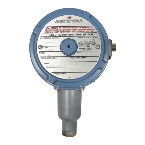
Date code format on nameplate is "YYWW" for year and week.
Part I -Installation
–Screwdriver/Adjustable Wrench to 1-1/2"
Tools Needed
MOUNTING
THe ConneCTIon of THe DevICe SHAll be MADe bY
CAble enTrIeS or A SToPPIng box CerTIfIeD In TYPe
of exPloSIon ProTeCTIon flAMeProof enCloSure 'd,'
SuITAble for THe ConDITIonS of uSe AnD CorreCTlY InSTAlleD.
THeSe ACCeSSorIeS SHAll be THreADeD InTo THe relevAnT
oPenIng(S) of THe DevICe, WITH AT leAST 5 THreADS engAgeD
AnD WITH AT leAST 8 mm lengTH of THreAD engAgeMenT. THeSe
ACCeSSorIeS Are noT InCluDeD WITHIn THe DevICe'S HAzArDouS
loCATIonS CerTIfICATe.
To PrevenT IgnITIon, SeAl All ConDuIT runS WITHIn 18
InCHeS of enCloSure.
AlWAYS HolD A WrenCH on THe PreSSure HouSIng Hex
WHen MounTIng unIT. Do noT TIgHTen bY TurnIng
enCloSure. THIS WIll DAMAge SenSor AnD WeAken
SolDer or WelDeD JoInTS.
InSTAll unITS WHere SHoCk, vIbrATIon AnD TeMPerATure
fluCTuATIonS Are MInIMAl. MounT unIT To PrevenT
MoISTure froM enTerIng THe enCloSure. IT IS
IMPerATIve To uSe ProPerlY rATeD exPloSIon-Proof SeAlIng
fITTIngS for eleCTrICAl WIre enTrY. Do noT MounT unIT
In AMbIenT TeMPerATureS THAT exCeeD THe lIMITS on THe
nAMePlATe for THe APProPrIATe AreA.
J120 enCloSureS Are ProvIDeD WITH TWo 3/4" nPT
eleCTrICAl ConDuIT oPenIngS, eITHer of WHICH or boTH
CAn be uSeD DurIng InSTAllATIon. A 3/4" exPloSIon
Proof Plug IS ProvIDeD for ProPerlY SeAlIng THe unuSeD
ConDuIT oPenIng. THe exPloSIon Proof Plug MuST be
ProPerlY SeAleD DurIng ProDuCT InSTAllATIon.
IMP120-14
IMP120-14
Advertisement
Table of Contents

Related Manuals for UE 120 Series


Summary of Contents for UE 120 Series
- Page 1 ConDuIT oPenIngS, eITHer of WHICH or boTH CAn be uSeD DurIng InSTAllATIon. A 3/4” exPloSIon The 120 Series pressure and differential pressure switches are Proof Plug IS ProvIDeD for ProPerlY SeAlIng THe unuSeD actuated when a bellows, diaphragm or piston sensor responds to ConDuIT oPenIng.
- Page 2 Types J120, J120K, H121, H121K, H122, H122K, H122P Figure 1a: Figure 1b H121, H121K, H122, H122K, H122P J120, J120K Mount controls vertically (pressure connection facing down, see figure use 75°C copper 1a) or horizontally (see figure 1b). Control may be surface mounted via conductors only.
- Page 3 Types H122P Part II - Adjustments Individual switches may be set together or separately by up to 60% Tools Needed of range. The front switch is set by turning the internal calibrating Screwdriver screw to the right for lower set point and turning to the left for higher 5/8”...
- Page 4 RE-GAPPING PROCEDURE zONE HAzARDOUS LOCATIONS FLAMEPROOF Tools Needed GAP AND JOINT DETAILS 5/8” open end Wrench 3/16” open end Wrench (2) Activation Plunger to adjustment screw hole gap joints: 1.140” min. length by 0.0030” max. annular gap gAPPIng IS fACTorY-SeT AnD CrITICAl To THe funCTIon of THe SWITCH.
- Page 5 Types J120, J120K Dimensions Dimension A Models Inches Pressure Internal Set Point Adjustment 126-164 7.25 184.2 Types J120, J120K S126b-S164b 7.63 193.8 171-174 8.72 221.5 183-186, 483-486 8.41 213.6 188-189, 488-489 7.47 189.7 190-194, 490-494 7.44 189.0 270-274 8.13 206.5 358-376 8.09 205.5...
- Page 6 When appropriate, this entry point should be sealed to prevent moisture entry. • Unit must not be altered or modified after shipment. Consult UE if modification is necessary. • Monitor operation to observe warning signs of possible damage to unit, such as drift in set point or faulty display. Check unit immediately.
Need help?
Do you have a question about the 120 Series and is the answer not in the manual?
Questions and answers