UE One Series Installation And Maintenance Instructions Manual
Electronic pressure and temperature switches
Hide thumbs
Also See for One Series:
Advertisement
Please read all instructional literature carefully and thoroughly before starting. Refer to the final page for the listing of Recommended
Practices, Liabilities and Warranties.
GENERAL
MISUSE OF THIS PRODUCT MAY CAUSE EXPLOSION AND PERSONAL INJURY. THESE INSTRUCTIONS MUST BE THOROUGHLY READ AND UNDERSTOOD
BEFORE UNIT IS INSTALLED.
WARNING: EXPLOSION HAZARD - SUBSTITUTION OF COMPONENTS MAY IMPAIR SUITABILITY FOR USE IN HAZARDOUS LOCATIONS.
WARNING: SEE THE PRODUCT NAMEPLATE INFORMATION FOR SPECIFIC AGENCY CERTIFICATIONS APPLICABLE TO YOUR PRODUCT.
2W2D MODELS
THIS EQUIPMENT IS SUITABLE FOR USE IN CLASS I, DIVISION 2, GROUPS A, B, C AND D; CLASS II, DIVISION 2, GROUPS F AND G; CLASS III; CLASS I, ZONE
2 AEx nC IIC T5; CLASS I, ZONE 2 Ex nC IIC T5; OR CLASS I, DIVISION 1, GROUPS A, B, C AND D; CLASS II, DIVISION 1, GROUPS E, F AND G; CLASS III;
CLASS I, ZONE 0 AEx ia IIC T5; CLASS I, ZONE 0 Ex ia IIC T5; WHEN INSTALLED PER DRAWING #A-62174-19 (NORTH AMERICA); OR NON-HAZARDOUS
LOCATIONS ONLY.
THIS EQUIPMENT IS ATEX CERTIFIED SUITABLE FOR APPROPRIATE USE IN GAS ZONE 2 & DUST ZONE 22 APPLICATIONS OR GAS ZONE 0 & DUST ZONE
20 APPLICATIONS WHEN INSTALLED PER DRAWING #A-62174-20 (EUROPE).
0539 DEMKO 03 ATEX 0322281X
II 1 G EEx ia IIC T5
II 1 D T+ 90ºC
-40ºC TAMB. +85ºC, IP66
2W3A MODELS
THIS EQUIPMENT IS SUITABLE FOR USE IN CLASS I, DIVISION 2, GROUPS A, B, C AND D; CLASS II, DIVISION 2, GROUPS F AND G; CLASS III; CLASS I, ZONE
2 AEx nC IIC T5; CLASS I, ZONE 2 Ex nC IIC T5; OR NON-HAZARDOUS LOCATIONS ONLY.
THIS EQUIPMENT IS ATEX CERTIFIED SUITABLE FOR APPROPRIATE USE IN GAS ZONE 2 & DUST ZONE 22 APPLICATIONS.
0539 DEMKO 03 ATEX 135585X
II 3 G EEx nL IIC T5
II 3 D T+ 90ºC
-40ºC ≤ TAMB. ≤ +85ºC, IP66
2WLP AND 8W2D* MODELS (* pending approvals)
THIS EQUIPMENT IS SUITABLE FOR USE IN CLASS I, DIVISION 2, GROUPS A, B, C AND D; CLASS II, DIVISION 2, GROUPS F AND G; CLASS III; CLASS I, ZONE
2 AEx nC IIC T4 CLASS I, ZONE 2 Ex nC IIC T4; OR NON-HAZARDOUS LOCATIONS ONLY.
THIS EQUIPMENT IS ATEX CERTIFIED SUITABLE FOR APPROPRIATE USE IN GAS ZONE 2 & DUST ZONE 22 APPLICATIONS.
0539 DEMKO 03 ATEX 0322281X
II 3 G EEx nL IIC T4
II 3 D T+ 130ºC
-40ºC ≤ TAMB. ≤ +80ºC, IP66
4W3A MODELS
THIS EQUIPMENT IS SUITABLE FOR USE IN CLASS I, DIVISION 2, GROUPS A, B, C AND D; CLASS II, DIVISION 2, GROUPS F AND G; CLASS III; CLASS I, ZONE
2 AEx nC IIC T4; CLASS I, ZONE 2 Ex nC IIC T4; OR NON-HAZARDOUS LOCATIONS ONLY.
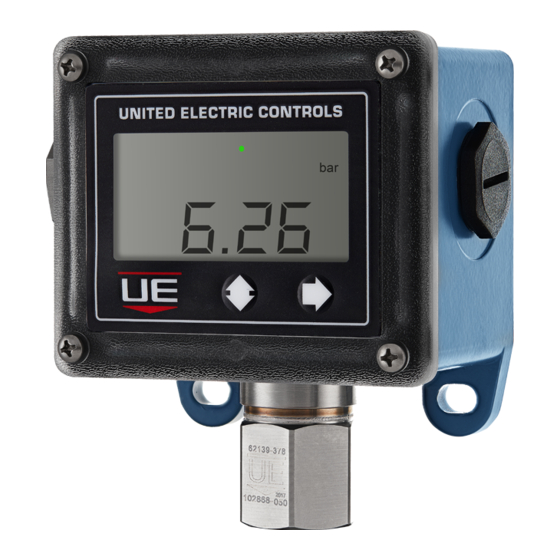
One Series Electronic Pressure
and Temperature Switches
Discrete Input and Loop-Powered
Models: 2W2D, 2W3A, 2WLP
External Powered
Models: 4W3A, 8W2D
IM_ONE-01
www.ueonline.com
U N I T E D E L E C T R I C
C O N T R O L S
Installation and Maintenance
Instructions
0539 DEMKO 03 ATEX 0322281X
II 3 G EEx nL IIC T5
II 3 D T+ 90ºC
-40ºC TAMB. +85ºC, IP66
IM_ONE-01
1
Advertisement
Table of Contents

Related Manuals for UE One Series


Summary of Contents for UE One Series
- Page 1 IM_ONE-01 One Series Electronic Pressure and Temperature Switches U N I T E D E L E C T R I C Discrete Input and Loop-Powered C O N T R O L S Models: 2W2D, 2W3A, 2WLP Installation and Maintenance...
- Page 2 Mount the unit using the two (2) 1/4" clearance holes in the mounting ears. Plumb sensor to the process port. See page 14 for dimensions. The One Series product may be mounted in any position except with the electrical conduit connection facing up. Ensure the process connection is sealed to the process port to prevent leakage.
- Page 3 T(amb) 38°C (100°F). DERATE 1.8 A/10°C (18°F). OVERLOADING THE SWITCH MAY CAUSE FAILURE. WARNING: THE ONE SERIES 8W2D MODEL ACCEPTS 12-30 VDC AS ITS POWER SOURCE. THE MAXIMUM LOAD RATING FOR EACH SWITCH IS SHOWN IN THE TABLE ON PAGE 5. OVERLOADING THE SWITCH MAY CAUSE FAILURE.
-
Page 4: Wiring Diagrams
The 4W3A has one terminal block labeled TB1. TB1 has four positions, marked with “L1”, “L2” and a switch symbol covering the remaining two positions. TB1 terminal block accepts 14-22 AWG wiring and the recommended torque is 3.5 in-lbs. The 8W2D has three terminal blocks, one located on the back of the display module and two, labeled TB1 and TB2, located on circuit board permanently mounted inside the enclosure. -
Page 5: Theory Of Operation
HIGH-POWER AND DUAL SWITCHING One Series model 4W3A incorporates a relay to provide a high-capacity switch rating of 280 VAC at up to 10 A. One Series model 8W2D provides 2 independent relays (see table on page 5 for details) and includes a field-scalable 4-20 mA analog output that is proportional to the process variable. These One Series Models require a separate power supply. - Page 6 (a list of the various parameters is outlined in the chart under Fault Codes, page 10). In the event of a fault condition, the One Series will attempt to display the problem and provide remote electrical indication. In the case of certain micro-controller faults, the revolving arrow may freeze or go out, indicating that a failure exists.
- Page 7 Process Display mode. KEY PROGRAMMING FEATURES SWITCH MODE: The One Series allows the switch output to be set up for either 3-state (I Am Working) or 2-state operation. For an overview of the I Am Working (IAW ® ) function, see page 6.
-
Page 8: Advanced Features
SET POINT: The set point is the value at which the One Series changes the state of the output. It is fully adjustable throughout the operating range of the unit (noted on the nameplate). Model 8W2D has two independent set points, one for each switch output. - Page 9 • 1 second • 2 seconds NOTE: The One Series typically responds to a process change in under 50 mSec. Using the Delay feature can lengthen the overall response time of the switch for certain types of pressure changes. • A shorter delay setting provides a faster response but is less stable.
-
Page 10: Fault Codes
SCALE: (2WLP and 8W2D models only) The 4-20 mA output on model 2WLP and 8W2D is field scalable. The default setting is 100% of sensor range, where 4 mA represents 0 and 20 mA is full range scale. If desired, both the 4 mA and 20 mA levels may be set independently to adjust the portion of the sensor's range represented by the 4-20 mA output. - Page 11 ACCEPTABLE SUPPLY VOLTAGES AND LOADS FOR 2W MODELS The charts below provide a range of acceptable power supply voltages (in Volts) and series loads (in Ohms). This is useful when the One Series 2-Wire is con- nected to non-standard PLC and DCS inputs or is connected in series with a relay or solenoid coil. For the 2W2D models a maximum of 30 VDC supply voltage and a load of 40 mA must not be exceeded.
- Page 12 • Order UE Part Number 62169-29 for the Barrier packaged separately from UE or your distributor, or • Order Option Code M036 for the Barrier packed with the 2W2D model from UE or your distributor, or • Order Part Number MTL 5012S directly from MTL or any of its distributors.
-
Page 13: Process Display
PROCESS DISPLAY IM_ONE-01 www.ueonline.com... -
Page 14: Dimensional Drawings
DIMENSIONAL DRAWINGS Models 4W3A, 2W2D and 2W3A (Single Conduit shown with Gauge Pressure Sensor) Models 8W2D and 2WLP (Dual Conduit shown with Temperature Sensor) IM_ONE-01 www.ueonline.com... -
Page 15: Sensor Options
SENSOR OPTIONS Gauge Pressure Differential Pressure 1/2" NPT (female) Temperature Model L Temperature Models H & C Temperature Model R IM_ONE-01 www.ueonline.com... - Page 16 When appropriate, this entry point should be sealed to prevent moisture entry. • Unit must not be altered or modified after shipment. Consult UE if modification is necessary. • Monitor operation to observe warning signs of possible damage to unit, such as drift in set point or faulty display.
Need help?
Do you have a question about the One Series and is the answer not in the manual?
Questions and answers