Table of Contents
Advertisement
Quick Links
Please read all instructional literature carefully and thoroughly before starting. Refer to the final page for the listing of
Recommended Practices, Liabilities and Warranties. For functional safety applications, please refer to the safety manual which
can be downloaded from www.ueonline.com.
GENERAL
Misuse of this device May cause explosion and personal
injury. these instructions Must be thoroughly read and
understood before device is installed.
this device is suitable for use in class i, division 1,
groups b, c and d; class ii, division 1, groups e, f and g;
class iii; or non-hazardous locations only. enclosure
type 4x, 7 & 9.
The device has been certified in accordance with the
applicable requirements of the following standards:
th
• iec 60079-0, 6
edition, revision date 2013/12
th
• iec 60079-1, 7
edition, revision date 2014/06
nd
• iec 60079-31, 2
edition, issue date 2013/11
• en 60079-0:2012+a11:2013
• en 60079-1:2014
• en 60079-31:2014
this device is atex certified for equipMent category 2.
suitable for appropriate use in gas zone 1 & dust zone
21 applications.
deMKo 09 atex 0815573x
0539 iecex ul 03.0001x
ii 2 g ex db iic t6 gb
ii 2 d ex tb iiic t85°c db ip66
-40°C ≤ Tamb. ≤ + 75°C
to prevent ignition of hazardous atMospheres,
disconnect supply circuits before opening. Keep cover
tight while circuits are energized.
MaxiMuM teMperature* stated in literature and on naMe-
plate Must never be exceeded, even by surges in the
systeM. occasional operation of unit up to Max. teMper-
ature is acceptable (e.g., start-up, testing). continuous
operation should be restricted to the designated adjustable
range.
*Maximum temperature - the highest temperature to which a sensing ele-
ment may be occasionally operated without adversely affecting set point
calibration and repeatability.
this device does not have any field replaceable parts.
any substitution of coMponents May iMpair suitability
for class i, division 1.
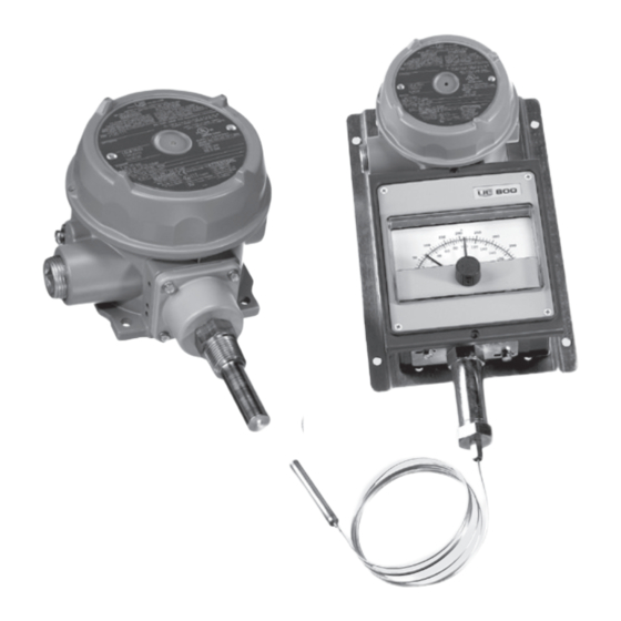
120 Series
Explosion-Proof Temperature and
Indicating Temperature Switches
and Controls
Local Mount Types B121, B122, C120
Remote Mount Types E121, E122, F120; 820E,
822E
SIL2
Certified
IMT120-12
www.ueonline.com
U N I T E D E L E C T R I C
C O N T R O L S
Installation and Maintenance
Instructions
the 120 series temperature switch utilizes either a liquid filled sensing stem
(immersion stem, direct mounting) or liquid filled sensing bulb (bulb & capil-
lary, remote mounting) to detect a temperature change. the response at
a pre-determined set point(s), actuates a spdt, dual spdt, or dpdt snap-
acting micro switch(es), converting the temperature signal into an electrical
signal. control set point(s) may be varied by turning the adjustment hex
(c120, f120) or the external knob(s) and pointer(s) (b121, b122, e121,
e122,820e, 822e) according to the procedures outlined (see part ii -
adjustments)
please refer to the product technical brocures for product specifications.
product technical brochures may be found at www.ueonline.com.
ue declarations and third party issued certifications are available for
download at www.ueonline.com/prod_approval.
date code format on nameplate is "yyww" for year and week.
Part I - Installation
– screwdriver/adjustable wrench to 1 1/2"
TOOLS NEEDED
MOUNTING
to prevent electrostatic discharge, wipe down cover
and enclosure of any dust build up before reMoving
cover.
install device where shocK, vibr ation and
teMperature fluctuations are MiniMal. do not Mount
device in aMbient teMperatures that exceed the
liMits on the naMeplate for the appropriate area
Mount device to prevent Moisture froM entering
the enclosure. it is iMperative to use properly rated
explosion-proof sealing fittings for electrical wire
entry.
to prevent ignition of hazardous atMospheres, seal
conduit runs within 18 inches of enclosure
types c120, f120, 820e and 822e are provided with two
3/4" npt electrical conduit openings, either of which or
both can be used during installation. a 3/4" explosion
proof plug* is provided for properly plugging the unused
conduit opening. the explosion proof plug Must be properly
installed.
*plug is approved explosion-proof with the product as a full assembly and does not carry indi-
vidual markings.
do not KnocKout any plugs on explosion-proof types 820e
or 822e
IMT120-12
Advertisement
Table of Contents

Related Manuals for UE B121


Summary of Contents for UE B121
-
Page 1: Installation And Maintenance
1, (c120, f120) or the external knob(s) and pointer(s) (b121, b122, e121, groups b, c and d; class ii, division 1, groups e, f and g;... - Page 2 the connection of the device shall be Made by WIRING cable entries or a stopping box suitable for the conditions of use and correctly installed, and disconnect all supply circuits before wiring device. certified by type of explosion protection - flaMeproof wire device in accordance with local and national enclosure ‘d’.
- Page 3 WIRING OF WIRING OF LOW SWITCH LOW SWITCH OPTION 1010, 1190, 1195 OPTION 1010, 1190, 1195 external knob and pointer (FOR TYPE B121, C120, E121, F120 ONLY) (FOR TYPE B121, C120, E121, F120 ONLY) TYPE 822E TYPE 822E adjustment DPDT DPDT Figure 4 N.O.
- Page 4 zONE hAzARDOUS LOCATIONS FLAMEPROOF GAP AND jOINT DETAILS 120’S activation plunger to adjustment screw hole gap joints: 1.140in/28.96mm min length by 0.0039in/0.099mm max annular gap plunger guide to enclosure through threaded joints: minimum 8 ½ fully engaged threads cover to enclosure through threaded joints: minimum 7 ½ fully engaged Figure 5: Indicating Enclosure Internals threads NOTE: indicating pointer adjustment (820e, 822e): use an accurate test...
-
Page 5: Temperature Sensors
Dimensions (Dimensional drawings for all models may be found at www.ueonline.com.) External Set Point Adjustment, Types B121, B122, E121, E122 Internal Set Point Adjustment, Types C120, F120 Dimension A Dimension A Model inches Model inches 9.12 231,4 immersion stem 8.97... - Page 6 When appropriate, this entry point should be sealed to prevent moisture entry. • Unit must not be altered or modified after shipment. Consult UE if modification is necessary. • Monitor operation to observe warning signs of possible damage to unit, such as drift in set point or faulty display.
Need help?
Do you have a question about the B121 and is the answer not in the manual?
Questions and answers