Advertisement
Please read all instructional literature carefully and thoroughly before starting. Refer to the final page for the listing of Recommended
Practices, Liabilities and Warranties. All Warnings are translated to French and can be found on pages 21 and 22.
GENERAL
MISUSE OF THIS PRODUCT MAY CAUSE EXPLOSION AND PERSONAL INJURY. THESE INSTRUCTIONS MUST BE THOROUGHLY READ AND UNDERSTOOD
BEFORE UNIT IS INSTALLED. SEE THE PRODUCT NAMEPLATE INFORMATION FOR SPECIFIC AGENCY CERTIFICATIONS APPLICABLE TO YOUR PRODUCT.
SUBSTITUTION OF COMPONENTS MAY IMPAIR SUITABILITY FOR USE IN HAZARDOUS LOCATIONS. CABLE GLANDS USED MUST BE RATED FOR A MINIMUM
OF IP66 IN ORDER TO MAINTAIN THE SAME IP RATING.
FOR ZONE HAZARDOUS LOCATIONS, ALL CABLE ENTRY DEVICES SHALL BE CERTIFIED IN TYPE OF EXPLOSION PROTECTION FLAMEPROOF ENCLOSURE "d"
WITH AN IP66 RATING, SUITABLE FOR THE CONDITIONS OF USE AND CORRECTLY INSTALLED. IF CABLES AND CABLE GLANDS ARE NOT USED, A STOPPING
BOX SHALL BE PROVIDED WITHIN 2" OF THE ENCLOSURE. FLAMEPROOF JOINT AND GAP DETAILS ARE PROVIDED ON PAGE 2.
INSTALL UNITS WHERE SHOCK, VIBRATION AND TEMPERATURE FLUCTUATIONS ARE MINIMAL. ORIENT UNIT TO PREVENT MOISTURE FROM ENTERING
ENCLOSURE. USE PROPERLY RATED SEALING FITTINGS FOR ELECTRICAL WIRE ENTRY. DO NOT MOUNT UNIT IN AMBIENT TEMPERATURES EXCEEDING
PUBLISHED LIMITS. THIS IS ESPECIALLY CRITICAL FOR LOCAL MOUNT TEMPERATURE UNITS. USE OF A SHROUD IS RECOMMENDED WHERE DIRECT SUNLIGHT
AND RAIN MAY COME IN CONTACT WITH THE ENCLOSURE.
DURING INSTALLATION, MARK THE BOX NEXT TO EACH PROTECTION METHOD ON THE NAMEPLATE THAT APPLIES TO YOUR APPLICATION.
THIS EQUIPMENT IS CERTIFIED IN ACCORDANCE WITH THE REQUIREMENTS OF THE FOLLOWING APPLICABLE STANDARDS (SEE TABLE 1) AND
IS SUITABLE FOR USE IN NON-HAZARDOUS AND THE FOLLOWING HAZARDOUS LOCATIONS, AND IS ATEX AND IECEX CERTIFIED SUITABLE FOR
APPROPRIATE USE IN GAS AND DUST ZONE 1 APPLICATIONS.
Cert number:
UL File E226592
Applicable Standards UL 913, UL-60079-0, UL 60079-11, CSA C22.2 No.
157-92, CSA C22.2 No. 60079-0:11, CSA C22.2 No.
60079-11:14
Suitable for appropri-
Class I, Div. 1, Groups A, B, C & D
ate use in:
Class II, Div. 1 Groups E, F & G
EXIA Intrinsically
Class III
Safe - Sécurité Intrin-
Class I, Zone 0 AEx ia IIC T4
séque
Ex ia IIC T4
Cert Number:
UL File E226592
Applicable Standards UL 1203, UL 60079-0, UL 60079-1, UL 61010-1, UL
50, UL 50E, CSA C22.2 No. 25, CSA C22.2 No. 30, CSA
C22.2 No. 60079-0:11, CSA C22.2 No. 60079-1:11, CSA
C22.2 No. 61010-1-12, CSA C22.2 No. 94.01-07, CSA
C22.2 No. 94.2-07
Suitable for appropri-
Class I, Div. 1, Groups A, B, C & D
ate use in:
Class II, Div. 1 Groups E, F & G
Class III
Class I, Zone 1 AEx db IIC T5 (1XSWLL)
Class I, Zone 1 Ex db IIC T5
Class I, Zone 1 AEx db IIC T3/T5 (1XSWHL & 1XSWHH)
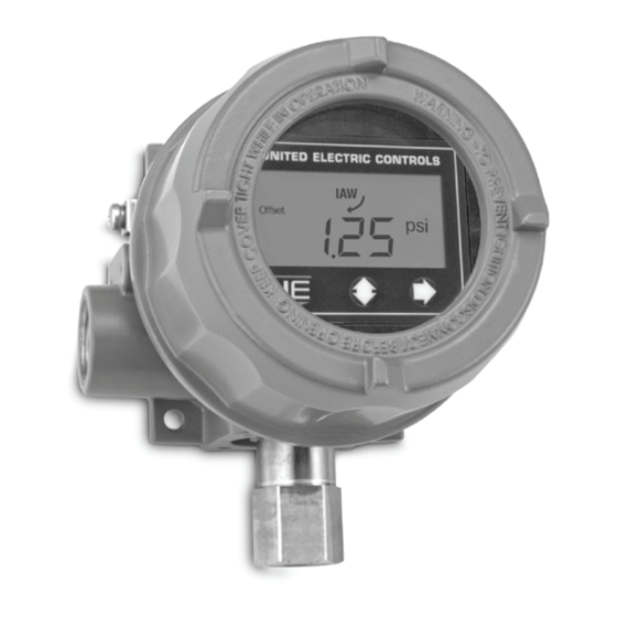
One Series
Electronic Pressure, Differential
Pressure and Temperature Switches
Discrete Input, Intrinsically Safe,
Flameproof and Non-Incendive
Models: 1XSWLL, 1XSWHL, and 1XSWHH
N. America
Intrinsic Safety - Model 1XSWLL Only
Flameproof - Models 1XSWLL, 1XSWHL and 1XSWHH
IM_1XSW-02
www.ueonline.com
U N I T E D E L E C T R I C
C O N T R O L S
Installation and Maintenance
Instructions
Europe
DEMKO 09 ATEX 0813748X
EN 60079-0:2012 + A11:2013
EN 60079-11:2012
II 1 G Ex ia IIC T4 Ga
II 1 D Ex ia IIIC T135°C Da
-40°C < TAMB < +85°C
DEMKO 09 ATEX 0813748X
EN 60079-0:2012 + A11:2013
EN 60079-1:2014
EN 60079-31:2014
II 2 G Ex db IIC T3/T5 Gb
II 2 D Ex tb IIIC T90°C Db
IP66
-40°C ≤ TAMB ≤ +85°C (1XSWLL)
-40°C ≤ TAMB ≤ +80°C (1XSWHL &
1XSWHH)
IM_1XSW-02
International
IECEx UL 08.0017X
IEC 60079-0:Ed.6(2011-06) +
Corr.1 (2012-01) + Corr.2 (2013-
12)
IEC 60079-11:Ed.2011
Ex ia IIC T4 Ga
Ex ia IIIC T135°C Da
-40°C < TAMB < +85°C
IECEx UL 08.0017X
IEC 60079-0:Ed.6(2011-06) +
Corr.1 (2012-01) + Corr.2 (2013-
12)
IEC 60079-1:Ed.7
IEC 60079-31:Ed.2
Ex db IIC T3/T5 Gb
Ex tb IIIC T90°C Db
IP66
-40°C ≤ TAMB ≤ +85°C (1XSWLL)
-40°C ≤ TAMB ≤ +80°C (1XSWHL
& 1XSWHH)
1
Advertisement
Table of Contents

Related Manuals for UE 1XSWLL


Summarization of Contents
GENERAL
Intrinsic Safety - Model 1XSWLL Only
Certifications and suitability for intrinsic safety applications, including N. America, Europe, and International standards.
Flameproof - Models 1XSWLL, 1XSWHL and 1XSWHH
Certifications and suitability for flameproof applications, covering N. America, Europe, and International standards.
HAZARDOUS LOCATION CERTIFICATIONS AND SAFETY
Non-Incendive Model Certifications
Details on non-incendive certifications and suitability for use in N. America, Europe, and International standards.
Flameproof Safety Conditions and Details
Specific safety requirements, joint details, and option descriptions for flameproof installations.
Intrinsic Safety Safety Conditions
Specific safety requirements for intrinsic safety installations, including special conditions.
PART I - MOUNTING
Mounting Procedures for Hazardous Locations
Describes mounting procedures for flameproof, non-incendive, and intrinsic safety installations.
Process Connections and Sensor Installation
Details on connecting process ports and sensors for hazardous location installations.
PART II - WIRING
Enclosure Cover and Display Module Removal
Procedure for safely removing the unit's enclosure cover and display module.
Wiring for Hazardous Installations
Specific wiring guidelines for flameproof and non-incendive installations.
WIRING DIAGRAMS
Models 1XSWLL and 1XSWHL Wiring
Wiring diagrams for the 1XSWLL and 1XSWHL models connected to PLC inputs or interposing relays.
WIRING DIAGRAMS
Model 1XSWHH Wiring
Wiring diagrams for the 1XSWHH model, including power supply and output connections.
WIRING TERMINALS AND BARRIERS
Terminal Block and Torque Details
Specifications for terminal blocks and recommended tightening torque for installations.
Intrinsic Safety Barrier Selection
Guidance on selecting appropriate intrinsic safety barriers for Model 1XSWLL.
PART III - PROGRAMMING
Entering the Programming Mode
Steps to access and enter the programming mode using the faceplate buttons.
Saving Programming Changes
Procedure for saving or discarding program changes after modification.
SWITCH CONFIGURATION
Setting Switch Mode, Set Point, and Deadband
Configuring switch operation modes, set points, and deadbands for accurate switching.
SWITCH LOGIC AND VALUE RESET
Switch Decision Logic
Visual guide illustrating switch behavior across different modes and set points.
Resetting Maximum & Minimum Values
Procedure to clear recorded minimum and maximum process values.
ADVANCED FEATURES
Adjusting Display Offset
Calibrating the display offset for improved accuracy with various sensor configurations.
Adjusting Span
Calibrating the sensor response curve slope to match reference values.
ADDITIONAL PROGRAMMING OPTIONS
Setting the Latch Mode (Manual Reset)
Configuring the switch to latch at the set point, requiring manual reset.
Setting the Plugged Port Feature
Enabling detection of plugged process ports via self-diagnostics.
DIAGNOSTICS AND FILTERING
Resetting Trip Counter
Resetting the count of times the set point has been reached.
Setting the Filter
Configuring a digital filter to prevent false trips from transient events.
Setting the Trip Delay
Configuring a delay before the switch trips after reaching the set point.
CALIBRATION AND ELECTRICAL SPECIFICATIONS
Display Module Calibration
Notes on display module and pressure sensor serial number matching for proper operation.
Acceptable Supply Voltages and Loads
Voltage and load characteristics for connecting 1XSWLL and 1XSWHL models to PLC/DCS inputs.
FAULT CODES
One Series Fault Codes
List and explanation of fault codes detected by the One Series IAW™ diagnostics.
TROUBLESHOOTING AND SUPPORT
Lost Passwords
Procedure for obtaining an unlock code for lost passwords.
Troubleshooting Electronic Switches
Methods for testing electronic switches by measuring voltage drop.
DIMENSIONAL DRAWINGS
Unit Dimensions and Mounting Kits
Visual representations of unit dimensions, conduit ports, sensor ports, and mounting kits.
SENSOR OPTIONS
Pressure Sensors
Diagrams and descriptions of gauge and differential pressure sensor types.
Temperature Sensors
Diagrams and descriptions of fixed local, spring loaded, and remote temperature sensors.
Dual Seal Gage Pressure Sensor (Option M041)
Description and diagram of the Dual Seal with Gage Pressure Sensor option.
Thermowell Adapter Kit Option W081
Description of the optional Thermowell Adapter Kit.
PRACTICES AND WARRANTY
Recommended Practices and Warnings
Best practices and important warnings for unit installation and operation.
Limited Warranty
Details of the product warranty, including coverage period and exclusions.
Limitation of Seller's Liability
Legal disclaimer regarding the seller's liability for product use or performance.
Need help?
Do you have a question about the 1XSWLL and is the answer not in the manual?
Questions and answers