UE One Series Installation And Maintenance Instructions Manual

UE One Series Installation And Maintenance Instructions Manual

Electronic pressure, differential pressure and temperature switches

Advertisement

Please read all instructional literature carefully and thoroughly before starting. Refer to the final page for the listing of Recommended
Practices, Liabilities and Warranties. All Warnings are translated to French and can be found on pages 21 and 22.
GENERAL
MISUSE OF THIS PRODUCT MAY CAUSE EXPLOSION AND PERSONAL INJURY. THESE INSTRUCTIONS MUST BE THOROUGHLY READ AND UNDERSTOOD
BEFORE UNIT IS INSTALLED. SEE THE PRODUCT NAMEPLATE INFORMATION FOR SPECIFIC AGENCY CERTIFICATIONS APPLICABLE TO YOUR PRODUCT.
SUBSTITUTION OF COMPONENTS MAY IMPAIR SUITABILITY FOR USE IN HAZARDOUS LOCATIONS. CABLE GLANDS USED MUST BE RATED FOR A MINIMUM
OF IP66 IN ORDER TO MAINTAIN THE SAME IP RATING.
FOR ZONE HAZARDOUS LOCATIONS, ALL CABLE ENTRY DEVICES SHALL BE CERTIFIED IN TYPE OF EXPLOSION PROTECTION FLAMEPROOF ENCLOSURE "d"
WITH AN IP66 RATING, SUITABLE FOR THE CONDITIONS OF USE AND CORRECTLY INSTALLED. IF CABLES AND CABLE GLANDS ARE NOT USED, A STOPPING
BOX SHALL BE PROVIDED WITHIN 2" OF THE ENCLOSURE. FLAMEPROOF JOINT AND GAP DETAILS ARE PROVIDED ON PAGE 2.
INSTALL UNITS WHERE SHOCK, VIBRATION AND TEMPERATURE FLUCTUATIONS ARE MINIMAL. ORIENT UNIT TO PREVENT MOISTURE FROM ENTERING
ENCLOSURE. USE PROPERLY RATED SEALING FITTINGS FOR ELECTRICAL WIRE ENTRY. DO NOT MOUNT UNIT IN AMBIENT TEMPERATURES EXCEEDING
PUBLISHED LIMITS. THIS IS ESPECIALLY CRITICAL FOR LOCAL MOUNT TEMPERATURE UNITS. USE OF A SHROUD IS RECOMMENDED WHERE DIRECT SUNLIGHT
AND RAIN MAY COME IN CONTACT WITH THE ENCLOSURE.
DURING INSTALLATION, MARK THE BOX NEXT TO EACH PROTECTION METHOD ON THE NAMEPLATE THAT APPLIES TO YOUR APPLICATION.
THIS EQUIPMENT IS CERTIFIED IN ACCORDANCE WITH THE REQUIREMENTS OF THE FOLLOWING APPLICABLE STANDARDS (SEE TABLE 1) AND
IS SUITABLE FOR USE IN NON-HAZARDOUS AND THE FOLLOWING HAZARDOUS LOCATIONS, AND IS ATEX AND IECEX CERTIFIED SUITABLE FOR
APPROPRIATE USE IN GAS AND DUST ZONE 1 APPLICATIONS.
Cert number:
UL File E226592
Applicable Standards UL 913, UL-60079-0, UL 60079-11, CSA C22.2 No.
157-92, CSA C22.2 No. 60079-0:11, CSA C22.2 No.
60079-11:14
Suitable for appropri-
Class I, Div. 1, Groups A, B, C & D
ate use in:
Class II, Div. 1 Groups E, F & G
EXIA Intrinsically
Class III
Safe - Sécurité Intrin-
Class I, Zone 0 AEx ia IIC T4
séque
Ex ia IIC T4
Cert Number:
UL File E226592
Applicable Standards UL 1203, UL 60079-0, UL 60079-1, UL 61010-1, UL
50, UL 50E, CSA C22.2 No. 25, CSA C22.2 No. 30, CSA
C22.2 No. 60079-0:11, CSA C22.2 No. 60079-1:11, CSA
C22.2 No. 61010-1-12, CSA C22.2 No. 94.01-07, CSA
C22.2 No. 94.2-07
Suitable for appropri-
Class I, Div. 1, Groups A, B, C & D
ate use in:
Class II, Div. 1 Groups E, F & G
Class III
Class I, Zone 1 AEx db IIC T5 (1XSWLL)
Class I, Zone 1 Ex db IIC T5
Class I, Zone 1 AEx db IIC T3/T5 (1XSWHL & 1XSWHH)
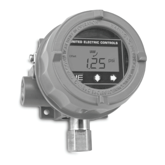
One Series
Electronic Pressure, Differential
Pressure and Temperature Switches
Discrete Input, Intrinsically Safe,
Flameproof and Non-Incendive
Models: 1XSWLL, 1XSWHL, and 1XSWHH
N. America
Intrinsic Safety - Model 1XSWLL Only
Flameproof - Models 1XSWLL, 1XSWHL and 1XSWHH
IM_1XSW-02
www.ueonline.com
U N I T E D E L E C T R I C
C O N T R O L S
Installation and Maintenance
Instructions
Europe
DEMKO 09 ATEX 0813748X
EN 60079-0:2012 + A11:2013
EN 60079-11:2012
II 1 G Ex ia IIC T4 Ga
II 1 D Ex ia IIIC T135°C Da
-40°C < TAMB < +85°C
DEMKO 09 ATEX 0813748X
EN 60079-0:2012 + A11:2013
EN 60079-1:2014
EN 60079-31:2014
II 2 G Ex db IIC T3/T5 Gb
II 2 D Ex tb IIIC T90°C Db
IP66
-40°C ≤ TAMB ≤ +85°C (1XSWLL)
-40°C ≤ TAMB ≤ +80°C (1XSWHL &
1XSWHH)
IM_1XSW-02
International
IECEx UL 08.0017X
IEC 60079-0:Ed.6(2011-06) +
Corr.1 (2012-01) + Corr.2 (2013-
12)
IEC 60079-11:Ed.2011
Ex ia IIC T4 Ga
Ex ia IIIC T135°C Da
-40°C < TAMB < +85°C
IECEx UL 08.0017X
IEC 60079-0:Ed.6(2011-06) +
Corr.1 (2012-01) + Corr.2 (2013-
12)
IEC 60079-1:Ed.7
IEC 60079-31:Ed.2
Ex db IIC T3/T5 Gb
Ex tb IIIC T90°C Db
IP66
-40°C ≤ TAMB ≤ +85°C (1XSWLL)
-40°C ≤ TAMB ≤ +80°C (1XSWHL
& 1XSWHH)
1

Advertisement

Table of Contents
loading

Summary of Contents for UE One Series

  • Page 1 IM_1XSW-02 One Series Electronic Pressure, Differential Pressure and Temperature Switches U N I T E D E L E C T R I C C O N T R O L S Discrete Input, Intrinsically Safe, Flameproof and Non-Incendive Installation and Maintenance...
  • Page 2: Applicable Standards

    The Unit must be cleaned with a damp cloth to avoid static discharge. Dual Seal Adaptor (Option M041) • Threaded Dual Seal Adaptor Option Enclosure to One Series Enclosure : 1”-20 UNEF-2, 10 threads engaged minimum • Breather element threaded joint: 1/4”-20 UNC-2, 10 threads engaged minimum •...
  • Page 3: Alarm Condition

    IAW™ self-monitors, searching for possible faults, both within the instrument and in the overall system (see Fault Codes, table 4, page 16). In the event of a detected fault, the One Series will attempt to display the fault details and provide remote electrical indication by opening (turning off) the IAW™...
  • Page 4 The device may be mounted in any position except with the sensor connection facing up. Ensure the process connection is sealed to the process port to prevent leakage. Care should be taken to minimize effects of shock and vibration. The One Series should be protected from direct sunlight and rain in outdoor installations using a shroud (user supplied).
  • Page 5 Minimum insertion depth is 2-1/2”. Sensor dimensional drawings are shown on page 20. PART II - WIRING Removing the One Series Enclosure Cover and Display Module TO PREVENT ELECTROSTATIC DISCHARGE WIPE DOWN COVER AND ENCLOSURE OF ANY DUST BUILD-UP BEFORE REMOVING COVER.
  • Page 6 Maximum Switch Ratings – Flameproof and Non-Incendive Model Signal Name Voltage Rating Current Rating 7.8 – 50.0 VDC 0.1 amperes 1XSWLL 7.8 – 50.0 VDC 0.1 amperes 70 – 240 VAC/VDC 0.1 amperes 1XSWHL 7.8 – 50.0 VDC 0.1 amperes 70 –...
  • Page 7: Base Enclosure

    WIRING DIAGRAMS - Model 1XSWHH Model 1XSWHH requires 70 – 240 VAC @ 0.015 A external power supply for each device. Power for all One Series functions are provided by this power supply connection at TB2, terminals C (L1/H) and D (L2/N). Connections for the programmable solid state relay switch are made at TB2 terminals A and B.
  • Page 8 SELECTING AN INTRINSIC SAFETY BARRIER (Model 1XSWLL) For Intrinsically-Safe (I.S.) installations, please reference the Control Drawing UE 62174–64 for Intrinsic Safety entity parameters and wiring information (https://www.ueonline.com/support/product-drawings/). Model 1XSWLL must be wired to an approved I.S. galvanically isolated barrier for Zone 0 EPL Ga and Class I, Division 1 classifications.
  • Page 9: Basic Features

    The One Series will resume monitoring the process (go back online) recalling all previously saved parameters from memory. BASIC FEATURES Setting the Units of Measure The One Series allows the units of measure to be set in the field. The default units are pounds per square inch (PSI) for pressure models IM_1XSW-02 www.ueonline.com...
  • Page 10 Press the right g button to enter a new Deadband. DB will show on the display. NOTE: The Deadband is the amount above or below the set point at which the One Series resets the switch, returning it to the normally closed or open state.
  • Page 11: Switch Mode

    Resetting the Maximum & Minimum Values The One Series continuously captures the readings from the sensor and stores one minimum and maximum value since the last time they were reset. The values can be viewed at any time by removing the enclosure cover and pushing the left 2 button. The display will scroll the values and then return to the Process Display mode.
  • Page 12: Advanced Features

    Adjusting Display Offset The One Series is factory calibrated to 0.25% of the sensor’s maximum range at room temperature. In some installations, it may be necessary to adjust the display’s offset due to the range and position of the sensor. Chemical seals with long capillaries combined with low maximum range sensors are a common cause of offset error.
  • Page 13 SETTING THE PLUGGED PORT FEATURE The One Series IAW™ self-diagnostics have the ability to detect that the process port may be plugged. It does this by monitoring the sensor for changes over time. The amount of change and the time period are programmable. If the process variable does not change by the amount and selected time period, the display will indicate PLUG and the IAW™...
  • Page 14: Setting The Filter

    Press the right g button to enter the time constant and return to main menu. NOTE: The One Series typically responds to a process value change in less that 100 milliseconds when the Filter is set to off. Using this feature can lengthen the overall response time of the One Series for certain types of process value changes (pressure spikes).
  • Page 15 PLC and DCS inputs or is connected in series with a relay or solenoid coil. NOTE: If you need assistance with determining the compatibility of the One Series with your PLC, DCS, or relay, we can help. Please have the manu- facturer's model number ready when you call us.
  • Page 16 A list of fault conditions is shown below: If a fault message appears on the One Series display, a fault code can be obtained by pressing both keypad buttons 2g simultaneously. Please provide this code if calling UE Inside Sales for assistance.
  • Page 17: Lost Passwords

    ANY VARIABLE TEXT SHOWN IS BETWEEN * MARKS. WARNING: AGENCY CRITICAL DOCUMENT. The switches contained in the One Series are electronic. The on/off switch signal is produced by a transistor or a solid-state relay, depending on the NO REVISIONS WITHOUT CERTIFICATION ENGINEER APPROVAL One Series model.
  • Page 18 PLUG 1MIN PORT 8888 If OFF is selected, 24HR Set Window pressing will return to menu PLUG One Series Un-shaded = Display Toggles PORT Software RESET 8888 Flowchart CLR? TRIP CNT DELAY Shaded = Display Scrolls *Denotes shortcut to Save Changes *OFF and 1/4 Sec.
  • Page 19: Dimensional Drawings

    DIMENSIONAL DRAWINGS 3/4” - 14 NPT 3/4” - 14 NPT CONDUIT PORTS CONDUIT PORTS 5.7” 6.1” [144.78] [154.94] 5.3” 5.4” [134.62] [137.16] [134.62] [137.16] 1”-20 NPT 1”-20 NPT SENSOR PORT SENSOR PORT GAGE PRESSURE DIFFERENTIAL PRESSURE 3/4” - 14 NPT 3/4”...
  • Page 20: Sensor Options

    [6.35] mm [6.35] mm 1/2” NPT COMPRESSION FITTING MINERAL INSULATED CABLE TEFLON INSULATION 300 SERIES st/st Ø0.125, [3.18] mm (FOR DC UNITS) Thermowell Adapter Kit Option W081 (UE Part #62169-44) THERMOWELL ADAPTER 0.250 [6.35] mm SENSOR 0.375 REF [9.53] mm 2.50 [63.5] mm...
  • Page 21 FRENCH WARNING TRANSLATIONS Page Warning Text Texte d’advertissement Misuse of this product may cause explosion and personal Utilisation abusive de ce produit peut causer une explosion et des injury. These instructions must be thoroughly read and un- blessures. Ces instructions doivent être soigneusement lues et com- derstood before unit is installed.
  • Page 22 FRENCH WARNING TRANSLATIONS CONT. To prevent electrostatic discharge, wipe down Pour éviter les décharges électrostatiques, nettoyez le capot cover and enclosure of any dust build-up before et le boîtier de toute accumulation de poussière avant de removing cover. retirer le capot. Disconnect all supply circuits before wiring device.
  • Page 23 24 months from the date of manufacture by the Seller (36 months for the Spectra 12 and One Series products; 18 months for Temperature Sensors). Seller shall not be obligated under...

This manual is also suitable for:

1xswll1xswhl1xswhh

Table of Contents