Table of Contents
Advertisement
Quick Links
Please read all instructional literature carefully and thoroughly before starting. Refer to the final page for the listing of Recommended
Practices, Liabilities and Warranties. All Warnings are translated to French and can be found of pages 22 and 23.
GENERAL
MISUSE OF THIS PRODUCT MAY CAUSE EXPLOSION AND PERSONAL INJURY. THESE INSTRUCTIONS MUST BE THOROUGHLY READ AND UNDERSTOOD
BEFORE UNIT IS INSTALLED. SEE THE PRODUCT NAMEPLATE INFORMATION FOR SPECIFIC AGENCY CERTIFICATIONS APPLICABLE TO YOUR PRODUCT.
SUBSTITUTION OF COMPONENTS MAY IMPAIR SUITABILITY FOR USE IN HAZARDOUS LOCATIONS.
FOR ZONE HAZARDOUS LOCATIONS, ALL CABLE ENTRY DEVICES SHALL BE CERTIFIED IN TYPE OF EXPLOSION PROTECTION FLAMEPROOF ENCLOSURE "d"
WITH AN IP66 RATING, SUITABLE FOR THE CONDITIONS OF USE AND CORRECTLY INSTALLED. IF CABLES AND CABLE GLANDS ARE NOT USED, A STOPPING
BOX SHALL BE PROVIDED WITHIN 2" (5CM) OF THE ENCLOSURE. FLAMEPROOF JOINT AND GAP DETAILS ARE PROVIDED ON PAGE 2.
INSTALL UNITS WHERE SHOCK, VIBRATION AND TEMPERATURE FLUCTUATIONS ARE MINIMAL. ORIENT UNIT TO PREVENT MOISTURE FROM ENTERING
ENCLOSURE. USE PROPERLY RATED SEALING FITTINGS FOR ELECTRICAL WIRE ENTRY. DO NOT MOUNT UNIT IN AMBIENT TEMPERATURES EXCEEDING
PUBLISHED LIMITS. THIS IS ESPECIALLY CRITICAL FOR LOCAL MOUNT TEMPERATURE UNITS. USE OF A SHROUD IS RECOMMENDED WHERE DIRECT SUNLIGHT
AND RAIN MAY COME IN CONTACT WITH THE ENCLOSURE.
IN ORDER TO MEET THE ELECTROMAGNETIC COMPATIBILITY REQUIREMENTS SPECIFIED IN EN61000-6-2: IMMUNITY FOR INDUSTRIAL ENVIRONMENTS,
EXTERNAL WIRING MUST BE RUN USING CABLE WITH A GROUNDED SHIELD OR CABLE RUN INSIDE OF A GROUNDED METAL CONDUIT
INTERFERENCE FROM IMPROPERLY SHIELDED VFD'S (VARIABLE FREQUENCY DRIVES) AND MOTOR CONTROLLERS MAY CAUSE NUISANCE TRIPS.
DURING INSTALLATION, MARK THE BOX NEXT TO EACH PROTECTION METHOD ON THE NAMEPLATE THAT APPLIES TO YOUR APPLICATION.
THIS EQUIPMENT IS CERTIFIED IN ACCORDANCE WITH THE REQUIREMENTS OF THE FOLLOWING APPLICABLE STANDARDS (SEE TABLE 1) AND
IS SUITABLE FOR USE IN NON-HAZARDOUS AND THE FOLLOWING HAZARDOUS LOCATIONS, AND IS ATEX AND IECEX CERTIFIED SUITABLE FOR
APPROPRIATE USE IN GAS AND DUST ZONE 1 APPLICATIONS.
Model 2SLP
N. America
Cert Number:
UL File E226592
Applicable
UL 50, UL 50E, UL 61010-1, UL 1203, CSA C22.2 No.
Standards
25-1966, CSA C22.2 No. 30-M1986, CSA C22.2 No.
94.01-07, CSA C22.2 No. 94.02-07, CSA C22.2 No.
61010-1, UL 60079-0, UL 60079-1, CSA 22.2 No.
60079-0:11, CSA 22.2 No. 60079-1:11
Suitable for
Class I, Div. 1, Groups A, B, C & D
appropriate use in:
Class II, Div. 1 Groups E, F & G
Class III
Class I, Zone 1 AEx db IIC T3/T5*
Ex d IIC T3/T5*
*Straight pressure sensor models P06-P16 have a temperature class of T3, all others T5
FLAMEPROOF AND DUST-IGNITION PROOF - SPECIAL CONDITIONS FOR SAFE USE
•
Field wiring must be rated 105°C minimum. For ambient temperatures below -10°C, use suitable field wiring.
•
Blanking elements from factory have been tested for flameproof "d" and dust "tb" with the enclosure as an assembly and carry no markings.
•
A suitable thermowell made from corrosion-resistant material and engaging 5 threads minimum (with thread sealant) is required for the local
spring loaded temperature sensor to maintain IP66
One Series Field Safety System™
Electronic Pressure, Differential Pressure,
and Temperature Transmitter Switch
Model: 2SLP
Flameproof
IM_ONE_Safety-07
www.ueonline.com
U N I T E D E L E C T R I C
C O N T R O L S
Installation and Maintenance
Instructions
Europe
DEMKO 09 ATEX 0813748X
EN 60079-0: 2012 + A11:2013
EN 60079-1:2014
EN 60079-31:2014
II 2 G Ex db IIC T3/T5* Gb
II 2 D Ex tb IIIC T90°C Db
IP66
-40°C ≤ TAMB ≤ +70°C
IM_ONE_Safety-07
International
IECEx UL 08.0017X
IEC 60079-0, Ed.6 (2011-06)
+ Corr.1 (2012-01) + Corr.2
(2013-12)
IEC 60079-1:Ed.7
IEC 60079-31:Ed.2
Ex db IIC T3/T5* Gb
Ex tb IIIC T90°C Db
IP66
-40°C ≤ TAMB ≤ +70°C
Table 1
1
Advertisement
Table of Contents

Related Manuals for UE Field Safety System One Series


Summary of Contents for UE Field Safety System One Series
- Page 1 IM_ONE_Safety-07 One Series Field Safety System™ Electronic Pressure, Differential Pressure, U N I T E D E L E C T R I C and Temperature Transmitter Switch C O N T R O L S Model: 2SLP Installation and Maintenance Instructions Please read all instructional literature carefully and thoroughly before starting.
- Page 2 The One Series Field Safety System™ incorporates UE’s patented IAW™ self-diagnostics, redundant and diverse signal processing, and software algo- rithms to detect abnormalities in the process, and internal faults within. The device meets the latest IEC 61508 standard for SIL 2 SIS and the requirements of SIL 2 for random integrity at HFT = 0, SIL 3 for random integrity at HFT = 1, and SIL 3 for systematic capability.
-
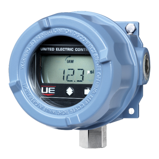
Page 3: Alarm Condition
I Am Working (IAW ™ ) The One Series Field Safety System™ also contains UE’s patented IAW™ self-diagnostic software. On a continuous basis, the IAW™ algorithm checks for proper operation, and locally reports the status using messages or revolving arrows on the display. For remote reporting, a discrete IAW™... - Page 4 For existing thermowells with 0.375” bore, an insert is available from UE as part number 62169-44 (see Figure 2). The adapter provides a faster heat transfer by adapting the 0.250” diameter temperature sensor housing to a larger bore 0.375” thermowell. Heat transfer compound is recommended in the bottom of the well and inside the adapter opening.
- Page 5 PART II - WIRING Removing the One Series Enclosure Cover and Display Module Field Safety System™ TO PREVENT ELECTROSTATIC DISCHARGE WIPE DOWN COVER AND ENCLOSURE OF ANY DUST BUILD-UP BEFORE REMOVING COVER. DISCONNECT ALL SUPPLY CIRCUITS BEFORE WIRING DEVICE. WIRE DEVICE IN ACCORDANCE WITH LOCAL AND NATIONAL ELECTRICAL CODES.
- Page 6 The One Series Field Safety System™ enclosure includes two conduit openings, WIRING DIAGRAMS - MODEL 2SLP one intended for the high-power SAFETY RELAY OUTPUT (SRO) wiring and the other intended for low-level signal and analog 4-20 mA wiring. 4-20 mA signals shall be wired using a shielded/twisted pair to minimize the effects of electrical interference.
-
Page 7: Power Options
Power Options Logic Solver Analog Inputs Ain1+ Loop Powered by the 4-20 mA signal. Use this configuration for 2-wire transmitter only function (Figure 7). NOTE: If IAW is not monitored, 24 VDC Loop the SFF of the device is reduced. Reference the product FMEDA report. Power www.ueonline.com/techinfo/one_series_st_fmeda_report.pdf Figure 7... - Page 8 The following wiring diagrams show the One Series Field Safety System™ fully configured where the health status (IAW) and SRO switch status signals are being monitored by a logic solver (PLC or DCS). These connections are not required; however, UE recommends monitoring the IAW signal to maximize the safe failure fraction in an SIS application.
-
Page 9: Fault Current
ONE SERIES 4-20mA POWER SUPPLY AND LOAD LIMITS 1200 181.8 333.3 681.8 Power Supply and Load Limits 227.3 381.0 727.3 1000 272.7 428.6 772.7 318.2 476.2 818.2 Rmin 363.6 523.8 863.6 Rmax 47.6 409.1 571.4 909.1 95.2 454.5 619.0 945.5 142.9 500.0 666.7... -
Page 10: Basic Programming
PART III - PROGRAMMING Basic Programming Tools Required: Programming Flowchart (see Flowchart 1, page 19) Programming of the One Series Field Safety System™ is accomplished using the two buttons on the faceplate (labeled 2 and g see Figure 15). Stepping down through the main menu using the left 2 button, you can access the various commands of the software menu. -
Page 11: Basic Features
BASIC FEATURES Setting the Units of Measure The One Series Field Safety System™ allows the units of measure to be set in the field. The default units are pounds per square inch (PSI) for pressure models and degrees Fahrenheit (˚F) for temperature models. •... - Page 12 • Press the right g button to view and change deadband. Press the left 2 button to increment the blinking digit. Press the right g button to enter and move to the next digit. • Press the right g button to enter a new Deadband. SW1 will show on the display. NOTE: The Set Point and Deadband settings are subject to the accuracy of the instrument.
-
Page 13: Advanced Features
ADVANCED FEATURES NOTE: No initial configuration of these features is required. The default for these advanced commands is zero or off. Adjusting Display Offset The One Series Field Safety System™ is factory calibrated to 0.25% of the sensor’s maximum range at room temperature. In some installations, it may be necessary to adjust the display’s offset due to the range and position of the sensor. - Page 14 NOTE: To return to factory calibration settings, enter all zeros for both SPAN and OFST. Setting the Latch Mode (Manual Reset) The Safety Relay Output can be configured to latch open when the set point is reached. Refer to the Programming Flowchart on page •...
-
Page 15: Setting The Filter
SETTING THE SRO FAULT MONITOR The SRO fault monitor senses the output of the relay and verifies that it is in the correct state. If the relay is closed when it should be open or open when it should be closed this feature will turn off IAW, set the output current to < 3.6 mA attempt to turn off the SRO and SRO Status outputs. A relay fault message will be displayed. - Page 16 SETTING THE SCALE The 4-20 mA output is field scalable. The default setting is 100% of the sensor’s maximum range, where 4 mA represents minimum and 20 mA is maximum range. If desired, both the 4 mA and 20 mA levels may be set independently to shrink or stretch the portion of the sensor’s range represented by the 4-20 mA output.
- Page 17 Table 5 NOTE: Power cycling the One Series will reset some faults. If the fault remains after power cycling, please contact UE Inside Sales at Insidesales@ueonline.com or call +1 (617)-923-6977. Some fault codes not noted above indicate microprocessor faults.
-
Page 18: Troubleshooting
0 VAC Table 7 LOST PASSWORDS Contact UE Inside Sales at +1-617-923-6977 or go online at www.UEonline.com/UUC to obtain a unique unlock code. The Kanban number from the product nameplate is required (see Figure 19). 6211-847 Kanban number and Date Code... - Page 19 Display to Scroll : Display to Scroll : MAX xxxx, MIN xxxx SP1 xxxx, DB1 xxxx, SP2 xxxx, DB2 Process Display xxxx 1234 Flash Err ABORT SAVING BOTH CHANGE Set Blinking Digit Set Blinking Digit Abort Abort Increments Blinking Digit ...
-
Page 20: Dimensional Drawings
DIMENSIONAL DRAWINGS 3/4” - 14 NPT 3/4” - 14 NPT CONDUIT PORTS CONDUIT PORTS 5.7” 6.1” [144.78] [154.94] 5.3” 5.4” [134.62] [137.16] [134.62] [137.16] 1”-20 NPT 1”-20 NPT SENSOR PORT SENSOR PORT GAGE PRESSURE DIFFERENTIAL PRESSURE 3/4” - 14 NPT 3/4”... -
Page 21: Sensor Options
[6.35] mm [6.35] mm 1/2” NPT COMPRESSION FITTING MINERAL INSULATED CABLE TEFLON INSULATION 300 SERIES st/st Ø0.125, [3.18] mm (FOR DC UNITS) Thermowell Adapter Kit Option W081 (UE Part #62169-44) THERMOWELL ADAPTER 0.250 [6.35] mm SENSOR 0.375 REF [9.53] mm 2.50 [63.5] mm... - Page 22 FRENCH WARNING TRANSLATIONS Page Warning Text Texte d’advertissement Misuse of this product may cause explosion Utilisation abusive de ce produit peut causer une explosion et des blessures. and personal injury. These instructions must be Ces instructions doivent être soigneusement lues et comprises avant l’ appareil thoroughly read and understood before unit is est installé.
- Page 23 FRENCH WARNING TRANSLATIONS CONT. Page Warning Text Texte d’advertissement For differential pressure models (especially low Pour les modèles de pression différentielle (de pressions faibles), montez le range units), mount the sensor level to minimize niveau du capteur afin de minimiser tout décalage de lecture de pression. La any pressure reading offsets.
- Page 24 When appropriate, this entry point should be sealed to prevent moisture entry. • Unit must not be altered or modified after shipment. Consult UE if modification is necessary. • Monitor operation to observe warning signs of possible damage to unit, such as drift in set point or faulty display.
Need help?
Do you have a question about the Field Safety System One Series and is the answer not in the manual?
Questions and answers