
Related Manuals for Grundfos Polydos 412E


Summary of Contents for Grundfos Polydos 412E
- Page 1 GRUNDFOS INSTRUCTIONS Polydos 412E Polyelectrolyte Preparation System Installation and operating instructions Polydos 412E Installation and operating instructions (all available languages) http://net.grundfos.com/qr/i/99348124...
- Page 3 Polydos 412E English (GB) Installation and operating instructions ............4...
-
Page 4: Table Of Contents
• Observe the local safety regulations. Materials of the Polydos 412E ....14 • Make sure that the regulations for the prevention of accidents Technical data of the Polydos 412E control cabinet . -
Page 5: Safety Instructions
2. Safety instructions 2.5 Electrical hazards 2.1 Hazard statements WARNING The symbols and hazard statements below may appear in Grundfos Electric shock installation and operating instructions, safety instructions and Death or serious personal injury service instructions. ‐... -
Page 6: Storage And Handling
4. Product description Related information 4.1 Intended use 5.1 Ambient conditions for Polydos 412E systems The Polydos 412E is a fully automatic system for the continuous 3.2 Unpacking preparation of polyelectrolyte solution in a defined concentration. • Mount as soon as possible after unpacking. -
Page 7: Identification
Order data (year and order confirmation number) Certificate Code for week and year of production PD412E-500-T0-P1-C1-A1-L1-Z1-W1 Marks of approval Without certificate 4.2.2 Type key of the Polydos 412E system With inspection certificate 3.1 With test report 2.2 Type With inspection certificate 3.1 and test report PD412E-500-T0-P1-C1-A1-L1-Z1-W1... - Page 8 4.2.3 Type key of the Polydos 412E control cabinet Type CP412E-05_10-P1-C1-A1-L1 Variant CP412E-05_10-P1-C1-A1-L1 For systems with a maximum preparation 05_10 capacity of 500-10000 l/h Supply voltage CP412E-05_10-P1-C1-A1-L1 400 VAC, 50 Hz (3ph, N, PE) 460 VAC, 60 Hz (3ph, PE)
-
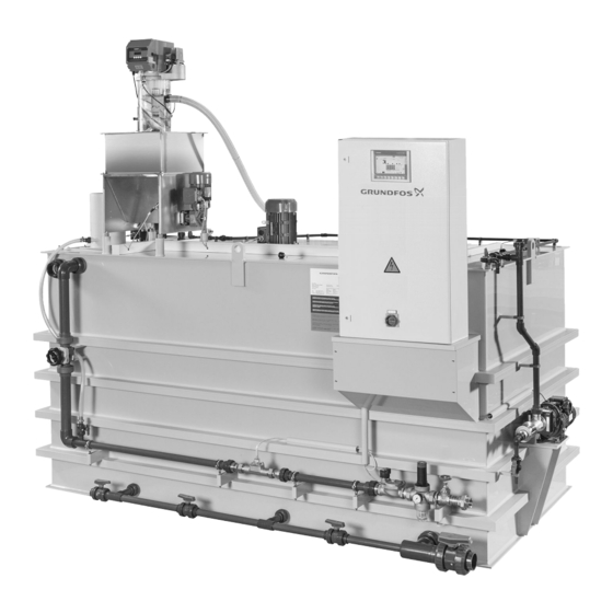
Page 9: Overview And Description Of Components And Connections
4.3 Overview and description of components and connections Pos. Description Pos. Description Water inlet Ultrasonic level sensor Shut-off valve Three-chamber tank Pressure reducing valve Mixing chamber Solenoid valve Maturing chamber Flow sensor Storage chamber Regulation valve Inspection holes Regulation valve for jet mixer Overflow outlet Heated dosing pipe Withdrawal connection... - Page 10 Three-Chamber tank (D6) The tank has three chambers. In the mixing chamber (D7), the polymer is mixed with water. In the maturing chamber (D8), the polymer solution matures. In the storage chamber (D9), the polymer solution is stored before withdrawal. The partition between the chambers prevents the amalgamation of the different solution phases, enables a constant withdrawal and guarantees the homogeneity of the solution.
-
Page 11: Piping And Instrumentation Diagram (Pid)
4.4 Piping and Instrumentation Diagram (PID) Pos. Description Pos. Description Water inlet Ultrasonic level sensor Shut-off valve Three-chamber tank Pressure reducing valve Mixing chamber Solenoid valve Maturing chamber Flow sensor Storage chamber Regulation valve Overflow outlet Regulation valve for jet mixer Withdrawal connection Heated dosing pipe Ball valve... -
Page 12: Process Description
4.5 Process description 5. Technical data The Polydos preparation system works fully automatic. It prepares 5.1 Ambient conditions for Polydos 412E systems the polymer solution in a combination of continuous preparation and batch preparation. Min./max. ambient temperature [°C] -5 / +50... -
Page 13: Dilution Water Parameters
Min. flow Rated current [A] 12.5 12.5 12.5 19.5 rate [m 5.5 Electrical data for components of the Polydos 412E Max. flow rate [m Stirrer 1 in mixing chamber The maximum flow rate must not be exceeded, otherwise Type designation: the flow sensor can be damaged. -
Page 14: Dimensions And Weights Of The Polydos 412E
PVC / brass suitable for the weight and dimensions of the system. Install the system on a horizontal foundation. 5.8 Technical data of the Polydos 412E control cabinet Maximum slope: 1:200 Make sure that the entire system is supported by the foundation. -
Page 15: Electrical Connection
Related information 5.4 Electrical data for Polydos 412E Fig. Start-up dry-material feeder 5.5 Electrical data for components of the Polydos 412E 7. Commissioning 7.1 Commissioning for operation with dry material Commissioning must be done by certified service persons. Wear personal protective equipment. -
Page 16: Commissioning For Operation With Liquid Concentrate
The next menu guides through the calibration of the dry-material Symbol Description feeder. Push these symbols to navigate through the menus. Push these symbols to navigate through the main steps. Indicates that contact type NO (normally open) is Fig. Start-up dry-material feeder active. - Page 17 Commissioning menus The next menu guides through the concentration adjustment of the prepared solution and through the water flow adjustment. This sequence of menus guides the certified service person through the commissioning procedure. Flow rates exceeding the upper limit of the water flow sensor can damage the sensor.
-
Page 18: Operation
The software stays property of Grundfos Water Treatment for producing an associated hazard assessment for the GmbH. Copies are not allowed. - Page 19 8.3.2.4 Help function The system provides a context-sensitive help function on the touchscreen. Symbol Description Push this symbol to activate the context-sensitive help function in the active menu. The symbol turns green to indicate the active help function. Touch the element you require help for to see the help information.
-
Page 20: Control Modes"Local" And "Remote
System messages 8.5 Operation mode "Automatic" In case of a system message, the following dialogue opens and In operation mode "Automatic" the system runs automatically. displays a respective message for 5 seconds: Screen Description symbol Automatic mode is not available. Operation mode "Manual"... -
Page 21: Menu Structure
8.7 Menu structure The following table shows the structure of menus which can be accessed via the main menu System overview (8.7.1 System overview). Symbol Submenu 1 Symbol Submenu 2 Symbol Submenu 3 Dry-material feeder (8.7.2 Dry-material feeder parameters) Start-up dry-material feeder (8.7.3 Dry-material feeder calibration) Liquid-concentrate pump... - Page 22 8.7.1 System overview Content area The menu System overview is shown after startup and during Symbol Description normal operation of the system. It shows system information and the status of the system. Indicates that dry polymer is present in the dry- Menu action Required user level material feeder.
- Page 23 Symbol Description Symbol Description Indicates the status of the level sensor in the A fieldbus connection is available. storage chamber. Push the symbol to activate control mode "Remote" and control the system via the fielbus • White: Sensor off connection. •...
- Page 24 8.7.2 Dry-material feeder parameters Display text/ Description Symbol In this menu, the settings of the dry-material feeder can be viewed and changed. Counter for the current dosing quantity (increasing by water flow and decreasing by running dosing Menu action Required user level screw).
- Page 25 8.7.3 Dry-material feeder calibration Symbol Description This menu guides you through the calibration procedure for the dry- material feeder. Push these symbols to navigate through the main Menu action Required user level steps. Access menu System Operator Change settings Push these symbols to switch on or off the dry- material feeder.
- Page 26 8.7.4 Liquid-concentrate pump parameters Display text/ Description Symbol In this menu, the settings of the liquid-concentrate pump can be viewed and changed. Concentrati on of Concentration of liquid concentrate. Menu action Required user level undiluted solution: Access menu System Operator Reset counter Qm: Push this symbol to open the menu Start-up Change settings...
- Page 27 8.7.5 Liquid-concentrate pump calibration 8.7.6 Water unit This menu guides you through the calibration procedure for the In this menu, the settings of the water unit can be viewed and liquid-concentrate pump. changed. Menu action Required user level Menu action Required user level Access menu Access menu...
- Page 28 8.7.7 Set-up - Flow sensor 8.7.8 Tank In this menu, the water flow sensor signal can be calibrated and the In this menu, the settings of the tanks and the stirrers can be PLC input can be set. viewed and changed. The sensor signal X is mapped to the measuring range (F) of the sensor.
- Page 29 8.7.9 Set-up - Level sensor 8.7.10 Trend 1h / Trend 24h In this menu, the tank level sensor signal can be calibrated and the In these menus, the preparation process trend can be viewed. PLC input can be set. The sensor signal X is mapped to the tank level range (L). Menu action Required user level Access menu...
- Page 30 8.7.11 System menu Symbol Description This menu provides information on the manufacturer and the system as well as menus for general settings, management and Push this symbol to open the menu Service menu. configuration. Menu action Required user level Push this symbol to open the menu Message administration.
- Page 31 8.7.13 Operating hours counter 8.7.15 Time / Date The system has several operating hours counters. In this menu, the time and date settings can be viewed and changed. Menu action Required user level Menu action Required user level Access menu System Operator Access menu Reset counter...
- Page 32 Note down the passwords, especially the parameter input password. It is not possible to operate the system without Menu action Required user level a valid password. In case of problems with passwords call Grundfos Water Access menu System Administrator Treatment GmbH. Change settings...
- Page 33 8.7.17 Message administration 8.7.18 Status of PLC inputs/outputs In this menu, the system messages can be managed. This menu shows information on inputs and outputs of the PLC. Menu action Required user level Menu action Required user level Access menu Access menu System Operator System Operator...
-
Page 34: Service Menu
8.8 Service menu General settings The following general settings are available in the menu. In this menu, the system can be adapted to customer requirements. It is possible to change the output signals, switch Symbol Description on/off fieldbus communication, save or restore settings and switch the system from dry material to liquid polymer dosing (optional). - Page 35 8.8.1 Data backup Output Description signal In this menu, the factory settings and user settings can be saved or restored. Tank dry Empty tank alarm. Set by default for output: Signal run LSAL contact 3 Menu action Required user level Lack of dry material Access menu...
- Page 36 8.8.2 Fieldbus communication - control mode "Remote" 8.8.3 Fieldbus communication status and settings The system can be connected to a fieldbus network to control it via The fieldbus communication is set via menu Service menu. bus communication in control mode "Remote". As a standard the system can be connected to: Menu action Required user level...
- Page 37 8.8.4 MODBUS-TCP - Parameters Symbol Description In this menu, the bus communication settings for MODBUS-TCP PROFINET communication is selected. Only one can be viewed and changed. bus communication type can be selected at a time. To be able to select another communication type, Menu action Required user level push this symbol to deselect the communication...
- Page 38 8.8.5 MODBUS-RTU - Parameters Display text/ Description Symbol In this menu, the bus communication settings for MODBUS-RTU can be viewed and changed. Swapping is not activated. The sequence of reading and writing of bits is the same. Push the Menu action Required user level symbol to activate swapping.
- Page 39 8.8.7 Interface data Display text/ Description Symbol In this menu, the bus communication interface data can be viewed. It shows the status of signal exchange between the SCADA system Swapping is not activated. The sequence of and the Polydos PLC. reading and writing of bits is the same.
- Page 40 8.8.8 PROFIBUS-DP (option) 8.8.9 Output addresses (Polydos to SCADA) PROFIBUS DP communication is realised via a gateway to transfer Data block DB100: Register 0 … 9 (40001 - 40010) = DB100.DBW0 data from “MODBUS TCP Client” to “PROFIBUS Slave”. This …...
- Page 41 DBW4 - Register 2 / 40003 output word 3 DBD16 - Register 8, 9 / 40009, 40010 output double word 9 • Format: BOOL Address Description Format Type of signal • Type of signal: permanent Level in storage DB100.DBD16 REAL Actual value [%] Address Description...
- Page 42 8.8.10 Input addresses (SCADA to Polydos) Data block DB100: Register 16 … 19 (40017 - 40020) = Db100.DBW32 … DBW38 DBW32 - Register 16 / 40017 input word 1 • Format: BOOL • Type of signal: impulse Address Description State DB100.DBX32.0 Activate control mode "Remote"...
-
Page 43: Maintenance
9. Maintenance 9.1 Safety instructions for the basic maintenance of Polydos systems The basic maintenance tasks must be performed by trained users. Maintenance and repair tasks not described in this manual must only be performed by certified service persons. Switch off the main switch on the control cabinet before any work on the system components and lines. -
Page 44: Basic Maintenance Schedule
If the result of a check requires change, repair or adjustment which is not described in this manual, call certified service persons. Interval Component Task See section To be defined by the Polydos 412E system Clean the surfaces of the system. 9.3 Cleaning the system surface operating company 9.4 Checking and cleaning or replacing Pressure reducing Check the strainer. -
Page 45: Checking And Cleaning The Dry-Material Feeder
If the storage hopper is not yet empty, empty it. In order to get correct spare parts, contact Grundfos and provide the product number and the order data written on the nameplate of Visually inspect the dry-material feeder. - Page 46 Make sure the main switch cannot be switched on accidentally. Decommissioning for more than 24 hours Stop the system. Switch off the main switch. Make sure the main switch cannot be switched on accidentally. Put on the stipulated personal protective equipment. Observe the chemical manufacturer's safety data sheets (SDS) and safety instructions of the used chemicals.
-
Page 47: Fault Finding Via Alarm Messages
12. Fault finding via alarm messages WARNING Chemical hazard Death or serious personal injury ‐ Wear personal protective equipment. ‐ Observe the chemical manufacturer's safety data sheets (SDS) and safety instructions of the used chemicals. WARNING Electric shock Death or serious personal injury ‐... -
Page 48: Disposal
This system or parts of it must be disposed of in an environmentally sound way. Use appropriate waste collection services. If this is not possible, contact the nearest Grundfos company or service workshop. See also end-of-life information at www.grundfos.com/product-... - Page 49 Fax: +359 2 49 22 201 Albany, Auckland Turkey Hong Kong E-mail: bulgaria@grundfos.bg Tel.: +64-9-415 3240 GRUNDFOS POMPA San. ve Tic. Ltd. Sti. GRUNDFOS Pumps (Hong Kong) Ltd. Fax: +64-9-415 3250 Gebze Organize Sanayi Bölgesi Canada Unit 1, Ground floor, Siu Wai Industrial...
- Page 50 99348124 0219 ECM: 1255828...
Need help?
Do you have a question about the Polydos 412E and is the answer not in the manual?
Questions and answers