DataRemote Pots In a Box CDS-9090 User Manual
Lte voip dual band wi-fi router
Hide thumbs
Also See for Pots In a Box CDS-9090:
- Quick start manual (2 pages) ,
- User manual (73 pages)

Related Manuals for DataRemote Pots In a Box CDS-9090


Summary of Contents for DataRemote Pots In a Box CDS-9090
- Page 1 CDS-9090 LTE VoIP Dual Band Wi-Fi Router USER MANUAL WHAT CAN YOUR NEW DEVICE DO? Virtually every application that requires a copper hard-line can now be replaced with one device! Revision No. 004 April 2020...
- Page 2 PSTN Modem Data The DataRemote CDS-9090 wireless router with VoIP is a stand-alone device which facilitates clear and reliable voice quality over the Internet; it is fully compatible with Session Initiation Protocol (SIP) industry standards and can integrate with many other SIP devices and software on the market.
- Page 3 Scope of Work Materials List Pre-Work Phase 1 – DataRemote CDS-9090 device assembly/Pre-Test + Fire Panel location Phase 2 - Installation Tasks – Locate existing POTS lines Phase 3 - Cut-over Fire Panel Lines to new ATA device Phase 4 - Testing Fire Alarm Communication over DataRemote's CDS-9090 device.
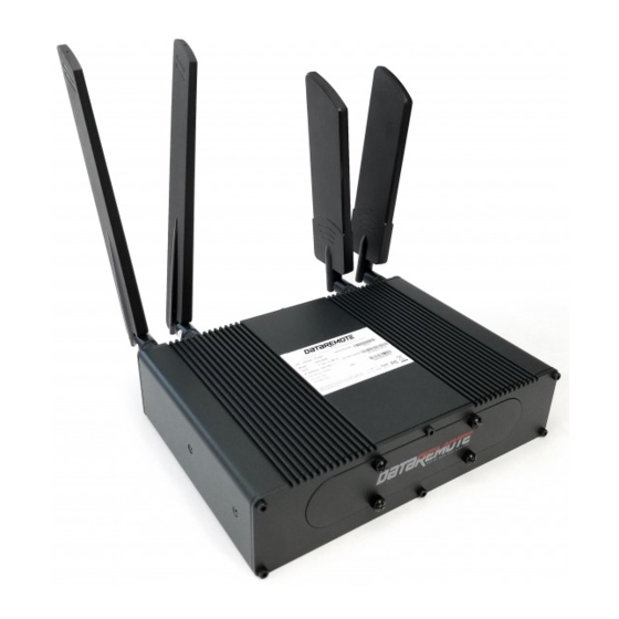
- Page 4 WHAT COMES IN THE BOX DATAREMOTE CDS-9090 DEVICE LTE AND WiFi ANTENNAS AC POWER ADAPTER ETHERNET AND PHONE (RJ11) CABLES SET OF MOUNTING MOUNTING BRACKET HARDWARE X1 Page 4 Revision No. 004 April 2020...
- Page 5 WHAT DO YOU NEED TO KNOW BEFORE INSTALLING YOUR DEVICE Before you can connect your DataRemote CDS-9090 device to the Internet and use it, you must have access to high-speed Internet. A high-speed Internet connection can be accessed through DSL, LTE wireless network, cable modem, Wi-Fi access point, or a leased line.
- Page 6 LED LIGHTS INDICATORS (continued) STATUS EXPLANATION BATTERY(BAT) On (GREEN) Battery charged On blinking (GREEN) Battery charging Battery low or not connected FXS ports On (GREEN) Registered Not registered On (GREEN) Active for key registration WiFi Client Non active for key registration On (GREEN) Wireless client connected On blinking (GREEN)
- Page 7 WHAT IS ON THE FRONT OF YOUR DEVICE? Cellular antennas connectors Wi-Fi antennas connectors Front panels ON/OFF LED status button AC power cord connector SIM cards slots Eight (8) Four (4) SFP outlet outlet FXS phone line Ethernet (High speed outlets outlets data transfer)
- Page 8 BASIC INSTALLATION (Continued) STEP 1 The SIM card slots are located on the left bottom corner of your device. Insert the SIM card inside the slot marked “SIM 1”. Make sure is inserted all the way into the slot. You will feel a spring lock the SIM card into place. Then connect one end of the power cord to the power port of your device, then connect the other end to an electric outlet.
- Page 9 Connect to one of the four LAN ports on your device with an Ethernet cable (RJ-45) to your equipment or computer that needs to receive an Internet connection from the DataRemote CDS-9090 device. Your device allows you to connect up to four (4) devices.
- Page 10 DataRemote CDS-9090 device’s FXS port. WARNING! Do not connect an active RJ-11 with voltage directly from the wall into the DataRemote device’s RJ-11 ports, this will damage the device permanently. Each DataRemote device’s RJ-11 FXS port is an active port supplying voltage. The FXS port is only to be connected to an FXO analog phone or another FXO device.
- Page 11 STEP 5 (continued) WARNING! Make sure the antennas do not touch each other, this will cause the connection to be degraded. STEP 6 Check the Power, WAN and LAN LEDs lights to make sure you are connected properly. Your device should look like this when connected to a phone line, WAN and one LAN/computer device.
- Page 12 Unpack, assemble then test DataRemote CDS-9090 device unit in "Standalone" Mode with power cable connected. Mount DataRemote device and test FXS 1-8 (if applicable) phone jacks by calling in/out using a telephone test set or a simple single line telephone and cell phone prior to connecting any device/appliance.
- Page 13 If Fire Alarm Panel, test that Fire Alarm Panels primary & secondary lines accordingly, calling out through the DataRemote CDS-9090 device. If RJ-31 style jack is used, verify that tip/ring connections are on pins 4 & 5 of jack.
- Page 14 DataRemote CDS-9090 device. a. Please report any store access issue to your Project Manager immediately. 3. The DataRemote device was shipped to the site in advance of your dispatch; please obtain this package from the Manager. IMPORTANT: Please open the package in front of MOD and inspect for a complete kit per the previous page's material's list;...
- Page 15 PHASE 1 DATAREMOTE CDS-9090 DEVICE ASSEMBLY /PRE-TEST + FIRE PANEL LOCATION. ASSEMBLE THE DATAREMOTE CDS-9090 DEVICE TO PRE-TEST: 1. Remove the CDS-9090 device and affix the antenna accordingly: WARNING! THE WiFi ANTENNAS CONNECTORS ARE DIFFERENT FROM THE LTE ANTENNAS CONNECTORS, SO FORCIBLY CONNECTING THEM INCORRECTLY WILL DAMAGE THE ANTENNAS AND POSSIBLY THE CDS-9090 DEVICE APPLIANCE COAXIAL PORT AS WELL.
- Page 16 DataRemote CDS-9090 device unit to the bracket with the included screws. If there are questions about the unit's placement, please contact Installation Support. 4. Plug the device into its permanent AC power; verify correct LED lights on the DataRemote CDS-9090 device.
- Page 17 1's (primary) new ATA number. Repeat steps 2 - 5 accordingly by performing the steps again using the phone 2-8 line ports of the DataRemote CDS-9090 device (If the lines are voice lines.) TESTING FIRE PANEL.
- Page 18 WARNING! DO NOT TOUCH THE EXISTING RJ-31 POTS JACKS NEAR FIRE PANEL UNLESS INSTRUCTED TO DO SO Once the Fire Panel is located, you will need to connect the DataRemote CDS-9090 device's phone 1-8 ports respectively with the Fire Alarm Panel's primary & secondary phone line ports preferably utilizing the existing cabling already connecting those ports to their current POTS lines.
- Page 19 Fire Alarm Panel need to be isolated from their telco POTS lines and redirected to the DataRemote CDS-9090 device’s phone ports using included 5' long phone cords. The method of termination of those lines coming back from the Fire Alarm Panel will dictate the next steps taken to cut them over to DataRemote CDS-9090 device.
- Page 20 “FIRE-Primary & FIRE-Secondary” SMT box respectively 5. Mark Cables: - Mark the DataRemote CDS-9090 device alarm line 1 port's phone cord with a "1" or "P" to reflect it connects to the DataRemote CDS-9090 device's alarm line 1 port.
- Page 21 Testing Fire Alarm communication over DataRemote's CDS-9090 device. NOTE: if you wish to know if the DataRemote CDS-9090 device's alarm lines have been set to auto please contact Project Manager. From the cut-over steps above, the Fire Alarm Panel may have already communicated its trouble condition and restoration to the alarm vendor, but we want to test it once again.
- Page 22 5. Call fire alarm vendor to confirm they show the error and that it has been cleared: - Have New DataRemote CDS-9090 device TN's recorded in your checklist handy to give to alarm vendor when calling, as well as store name and location # (number) - Confirm the fire alarm vendor is receiving The New DataRemote CDS-9090 device phone 1-8...
- Page 23 Testing Fax Lines. Fax Mode Details: Fax Works in VOIP and FAX modes on the DataRemote CDS-9090 device. Fax in Fax mode works in Basic (9600 Baud), Normal (14400 Baud) with ECM (Error Correction Mode) ON & OFF depending on the customers fax machine.
- Page 24 PHASE 5 (continued) Testing Fax Lines. Fax Testing: 1. Connect the respective FXS line that is provisioned for fax to the "Line" port of the customer Fax machine. 2. Make a test outbound Fax call to a number provided by your Program Manager. 3.
- Page 25 For all other Device installations follow same steps excluding RJ-31 biscuit connections and monitoring company communications. NOTE: The DataRemote CDS-9090 device LED FX lights run left -to-right (1 - 8) FXS ports Left to Right top row are 1,2,3,4 respectevely. Bottom row are 2,3,3,6,8 Advanced Programming Information.
- Page 26 Statements and Disclaimers FCC Radiation Exposure Statement DataRemote Incorporated, declares that this device is in compliance with the essential requirements and other relevant provisions of Directive 1999/5/EC. This equipment has been tested and found to comply with the limits for a Class B digital device, pursuant to part 15 of the FCC rules. These limits are designed to provide reasonable protection against harmful interference in a residential installation.
- Page 27 911 calling, Customer must register the new E911 CLID number and its associated address with DataRemote, in order to enable 911 capabilities for the updated number. Failure to do so may result in 911 services not being available to Customer when using an unregistered phone number If you use a Private Branch Exchange (PBX) telephone system, the 9-1-1 dispatcher may see only your corporate or billing address, not the location information of the emergency.
- Page 28 Manufacturer Model Name/Number DataRemote DataRemote DataRemote (Current Device for this Manual) Certified Devices CALIFORNIA ENERGY COMMISION Model Appliance Type Manufacturing Company Brand Regulatory Status Date DataRemote Federally-Regulated DataRemote, Inc. 11/12/2019 Incorporated Consumer Product Page 28 Revision No. 004 April 2020...
- Page 29 C E R T I F I C A T E O F C O M P L I A N C E 20190725-MH63085 Certificate Number MH63085-20190717 Report Reference 2019-JULY-25 Issue Date DATAREMOTE INC Issued to: 18001 Old Cutler Rd, Suite 600 Miami FL 33157 BATTERIES, HOUSEHOLD AND COMMERCIAL, This certificate confirms that INFORMATION TECHNOLOGY EQUIPMENT INCLUDING...
Need help?
Do you have a question about the Pots In a Box CDS-9090 and is the answer not in the manual?
Questions and answers