Table of Contents
Advertisement
WEGA MACCHINE PER CAFFÈ S.r.l.
Via Condotti Bardini, 1 - 31058 SUSEGANA (TV) - ITALY - Tel. +39.0438.1799700 - Fax +39.0438.1884890 - www.wega.it - info@wega.it
2006/42/CE Direttiva macchine
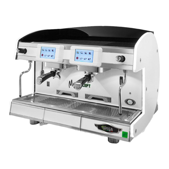
EVDP
ESPRESSO COFFEE MACHINE
Use and maintenance manual. TECHNICIANS instructions.
FONDO VERDE CHIARO PANTONE 376C
Advertisement
Table of Contents

Related Manuals for Wega MyConcept EVDP 2GR


Summary of Contents for Wega MyConcept EVDP 2GR
- Page 1 WEGA MACCHINE PER CAFFÈ S.r.l. Via Condotti Bardini, 1 - 31058 SUSEGANA (TV) - ITALY - Tel. +39.0438.1799700 - Fax +39.0438.1884890 - www.wega.it - info@wega.it 2006/42/CE Direttiva macchine EVDP ESPRESSO COFFEE MACHINE Use and maintenance manual. TECHNICIANS instructions. FONDO VERDE CHIARO PANTONE 376C...
- Page 2 IMPORTANT: Read carefully before use - Store for future reference Content rights The partial reproduction and dissemination of the contents in this document without the prior written consent of the Manufacturer is forbidden. The Company logo is owned by the Manufacturer of the Machine. Responsibility We are constantly striving to improve the accuracy of the information published in each Manual, but there may be some inaccuracies.
-
Page 3: Table Of Contents
ESPRESSO COFFEE MACHINE Use and maintenance manual. TECHNICIANS instructions English Summary INTRODUCTION ..............4 Service tuning ..............31 Guidelines for reading the Manual ........4 Washes ................32 Storing the Manual ............... 4 Check of dispensing ............33 Coffee tuning ..............34 Method for updating the Instruction Manual ...... -
Page 4: Introduction
INTRODUCTION ABBREVIATIONS Sect. = Section Chap. = Chapter Read this manual carefully. It provides important Par. = Paragraph information on the safety to the Technician during the Page operations indicated in this document. Fig. Figure Keep this Manual in a safe place. If you lose it, you can Tab. -
Page 5: Method For Updating The Instruction Manual
Method for updating the Instruction QUALIFICATION OF RECIPIENTS The machine is intended for professional and not Manual generalized use, so it can be used by Qualified Techni- The Manufacturer reserves the right to modify and cians, in particular who: make improvements to the machine without notifying • Have attended the training courses organized by the it and without updating the Manual already delivered. -
Page 6: Guarantee
Obligation to read the documentation automatically invalidates any guarantee. Customer service WEGA MACCHINE PER CAFFÈ S.r.l. Via Condotti Bardini, 1 - 31058 SUSEGANA (TV) - ITALY Tel. +39.0438.1799700 - Fax +39.0438.1884890 E-mail: info@wega.it - Web-site: www.wega.it... -
Page 7: Identification Of The Machine
IDENTIFICATION OF THE MACHINE the machine and dangerous situations for the operator and/or those close to the Machine, is considered incor- rect or improper. Make and model designation CONTRAINDICATIONS OF USE The identification and the model of the machine are found on the NAMEPLATE and in the EC DECLARATION The machine must not be used: OF CONFORMITY provided with the machine. -
Page 8: Machine Description
Machine description Illuminated side edge. Steam knob. Cool touch steam spout (*). Hot water nozzle ON switch Adjustable foot. Pull-out cup support grille. Filter holder. Dispensing compartment LED light 10. Display touch screen. 11. Cup-rest grid 12. USB socket. 13. Cup heater surface. (*) Autosteamer nozzle (optional). -
Page 9: Internal Components
Internal components Service boiler safety pressure switch. Services boiler heating element. Services boiler. Internal motor pump (if included). Coffee boiler pressure switch. Water inlet connection. Hot water mixer. Drain pad. Dispensing group. 10. Volumetric dispenser. 11. Coffee boiler. 12. Electronic control unit. 13. -
Page 10: Data And Ce Marking
• Y - year of manufacture; MARCHIO COMMERCIALE The data of the appliance can be seen also on the WEGA MACCHINE PER CAFFÈ S.r.l. label located on the package of the machine. Via C. Bardini,1 SUSEGANA (TV) - ITALY Tel. +39.0438.1799700 Fax +39.0438.1884890 S/N: Mod. - Page 11 2.6.3 2.6.1 Coffee boiler Dispensing group The dispensing group (A) is made up of a metallic Each dispensing group is equipped with a thermally block which is hooked onto the coffee boiler (B). insulated coffee boiler (1) for coffee hot water dispensing. Heat is provided by an electric heating element (2).
- Page 12 2.6.4 Electronic control unit 2.6.7 Automatic Water Entry The electronic control unit is the nerve The Automatic Water Entry system is for checking the center of the machine. It monitors and boiler level. It is composed of: controls all operation of the unit. • level probe (short) (1) and safety probe (long) (2)in- By entering the section "Menu"...
- Page 13 2.6.8 Pressure switch 2.6.11 Expansion - non-return valve The machine includes two types of pressure switches: This is a valve consisting of an expansion valve and a non-return valve. COFFEE BOILER PRESSURE SWITCH • expansion valve (A): Each coffee boiler is equipped with a pres- the cold water sent from the pump to the coffee boil- sure switch to control the pressure.
- Page 14 2.6.13 Cup heater 2.6.14 Cappuccino maker (optional) The cup heating device is for heating cups before The cappuccino maker can be optionally installed they are used. on the steam nozzle or directly on the tap. This device allows to both heat and foam the milk. For adjusting and cleaning, follow the provisions in the user's manual.
- Page 15 2.6.15 Autosteamer (optional) This system can be used for automatically heating and foaming milk at the programmed temperature. Below is listed its operating principle: • select the desired key on the display, for example • opening of the solenoid valve (2) with consequent flow of steam from the boiler to the Autosteamer Short dose automatic nozzle (9);...
- Page 16 2.6.16 Water filter 2.6.17 Softener Mains water contains insoluble salts, which cause the The resin softener can be used as an alternative to build-up of lime scale deposits in the boiler and other the water filter. parts of the machine. This component has the property of retaining the Drinking water can also contain traces of heavy met- calcium contained in the water.
-
Page 17: Transport And Handling
TRANSPORT AND HANDLING Handling the packed machine Upon arrival, the machine must be unloaded and handled with care, carefully following the instructions Safety precautions on the packaging, or those contained in this Manual. Handling operations must always and exclusively be performed If there is an external motor pump (optional), the mo- by qualified personnel and in compliance with applicable safety tor and the pump are provided in a separate package. -
Page 18: Storage
STORAGE INSTALLATION Overview Safety precautions In the waiting period prior to installation, the ma- Installation must always and exclusively be performed by qualified chine must be stored by the Manufacturer or Authorized personnel and in compliance with applicable safety and health Distributor. -
Page 19: Dpi Characteristics
DPI characteristics Installation space and operating space During installation of the machine, the following PPE Before the arrival of the machine, a suitable environ- are required: ment must be prepared: • Location suited to the intended use and adequate space for comfortable use of the machine; Mandatory use of protective gloves • adequate lighting, in accordance with applicable standards;... - Page 20 11. Water supply tap Support base 12. Water supply non-return valve Grinder-dispenser 13. Used coffee grounds drawer 20 cm minimum distance between the machine 14. Support for tapping the filter holder and the wall 15. Height of support base 90 cm Sewer drain Discharge tub Water supply inlet...
-
Page 21: Drilling The Support Base
Drilling the support base If it is necessary to drill holes on the support bench for passing the water inlet and outlet hoses, as well as the electrical supply cables, follow the directions in the drawings below. 2 GROUPS 200 mm Front of the machine 536 mm 3 GROUPS... -
Page 22: Hydraulic Connection
Hydraulic connection 5.7.1 Water supply The water supply of the appliance must be carried out with water which is suitable for human consump- tion, in compliance with the regulations in force in the place of installation. The owner/manager of the system must confirm to the installer that the water meets the requirements above: 5.7.2 Materials to be used... -
Page 23: Electrical Connection
Electrical connection • Installation must be done in accordance with the safety standards in force in the country of installation. The water supply must provide cold water for human consumption The owner/manager of the system must confirm to (potable water) at a pressure between 1,5 and 5 bars If the pressure the installer that the electrical system meets the re- is higher than 5 bar, connect a pressure reducer before the pump. -
Page 24: Commissioning
COMMISSIONING Coffee grinding To adjust the coarseness of the ground coffee, use Safety precautions the appropriate regulator located on the hopper of the The following residual risks are present during the grinder-dispenser. commissioning of the machine and cannot be elimi- nated: Electrical hazard: When using the electrical appliance, several safety... -
Page 25: Turning The Machine On And Off
Turning the machine on and off • after start-up, the machine is ready for coffee dispens- ing and the display will show the screen below; An After the electric and water connections have been orange steam icon indicates that it is necessary to made, make certain that the drain pan located under the wait a few minutes for the steam to be dispensed. -
Page 26: Water Replacement
MACHINE INFORMATION Water replacement During the installation of the machine, the Qualified The machine information is available on display: Technician must replace the water contained in the hy- • select the bar on the right side of the display; draulic circuits by following these steps: • select the menu key • when installation is complete, the appliance has to be started, brought to the nominal working condi-... -
Page 27: Parameter Programming
PARAMETER PROGRAMMING 8.1.1 Access by USB stick. • Insert the USB stick into the port (12); This paragraph deals with the programming menu • select the bar on the right side of the display; that allows the user to program the various functions • select the menu key of the machine. - Page 28 8.1.2 Access by Password Parameters can be reset at the user level: (code 3 in the USB stick) • Select the bar on the right side of the display; PARAMETER No. DESCRIPTION MEASUREMENT UNIT • select the menu key PRESSURE • select the service configuration key VOLUME • enter the password;...
-
Page 29: Programming Menu
Programming menu maintenance cycles type A-B-C reset date of the next maintenance set date 1 - maintenance report water consumption (lt) reset From the two pages of the menu you can ac- grind wear (kg) reset cess the complete programming of the machine. energy saved (kWh) reset Below is a summary of the programming sec-... -
Page 30: Maintenance Report
Maintenance report In this section you can view the following data: • maintenance cycles type A; • maintenance cycles type B; • maintenance cycles type C; • Water consumption (liters); • grinder wear (kg); • energy saved (kWh). To reset the data, select the button To program the date to request assistance for the machine, i.e. -
Page 31: Service Tuning
Services tuning This section allows to program all the parameters related to the machine services and, in particular: • boiler pressure; • boiler temperature in the energy saving phase; • cup-heater temperature; • boiler pressure during the boost phase; • duration of the boost phase. To change the data, use the buttons or the display keyboard To switch from one page to another, select the key... -
Page 32: Washes
Washes This section allows to program the automatic cycle and management of the washes: • date of last wash visualization; • enabling the automatic wash • enable wash at each start-up; • wash cycles number configuration; • wash duration configuration (min); • rinse duration configuration (sec);... -
Page 33: Check Of Dispensing
Dispensing control Program this section to view some information dis- played during the dispensing of the doses: • time visualization; • flow visualization; • temperature visualization. Use the keys to enable or disable the function. 0 = Disabled function 1 = Enabled function TECHNICIANS manual... -
Page 34: Coffee Tuning
Coffee tuning This section allows to set some parameters for coffee dispensing and, in particular: • group temperature; • group boiler temperature. To change the data, use the buttons or the display keyboard Programming must be carried out for each group. TECHNICIANS manual... -
Page 35: Language
Language This section allows to select the language displayed. To set the language, select the corresponding button. TECHNICIANS manual... -
Page 36: Recipe Management
Recipe management This section allows to attach a name to each coffee blend and customize it as follows: • blend name • set group boiler • set group • grinding degree This allows the user to select the desired blend any- time without changing any parameters. -
Page 37: Alarm History
Alarm history 8.10 This section allows to check all the machine anomalies over time. By selecting the button , the system displays the list in chronological order by date; by selecting the the list is proposed by type of alarm. To reset all data, press the key TECHNICIANS manual... -
Page 38: Filters
Filters 8.11 This section is dedicated to the management of wa- ter softeners and water filters. In particular, the system allows to: • display the water consumption of the machine • program the water replacement warning. To set the value, use the buttons , or the display keyboard Setting the value to zero, the warning system will... -
Page 39: Parameter List
Parameter list 8.12 This section allows to program all the machine pa- rameters. To change the data, use the buttons or the display keyboard To switch from one page to another, select the key The complete list of parameters is given in chap. "18. PARAMETER TABLE"... -
Page 40: Maintenance Thresholds
Maintenance thresholds 8.13 This section is dedicated to the management of the machine maintenance. • maintenance threshold type A-B-C; • display of missing cycles to threshold A-B-C; • display of threshold A-B-C next maintenance date; • days until maintenance; • short-normal-long single doses (grams) configura- tion;... -
Page 41: Usb
8.14 The USB allows to update the machine software and load useful data, in particular: • updating the keyboards/display software; • updating the control unit software; • loading the slide; • importing the parameters; • saving the parameters; • importing the languages. Press to perform the operation. -
Page 42: Inspections
Inspections 8.15 This section allows to monitor all the machine operat- ing data in real time, and in particular: • control unit temperature; • boiler temperature; • Autosteamer temperature; • cup-heater temperature; • pump pressure; • boiler pressure probe; • boiler pressure; • flow meter inlet;... -
Page 43: List Of Counters
Counters list 8.16 This section lists the count of all the deliveries, and in particular: • partial number of single coffees dispensed since the previous reset, in the versions: short, normal, and long for each group; • partial number of double coffees dispensed since the previous reset, in the versions: short, normal, and long for each group;... -
Page 44: Boiler Efficiency
Boiler efficiency 8.17 This section allows to check the efficiency of the boilers. The comparison between the different param- eters over time allows to assess the state of the boiler operation: • for each group boiler: time necessary to raise the temperature by 1 °C - last measurement;... -
Page 45: Parameter Reset
Parameter reset 8.18 This section allows to reset the initial programming data, and in particular: • user parameter reset; • technician parameter reset; • manufacturer parameter reset; To start resetting, select the desired button. TECHNICIANS manual... -
Page 46: Wifi Connection
WIFI CONNECTION If the machine is provided with the WIFI service, you can make the connection as follows: • check if the message that appears on bottom right of the display is inserted inside a white rectangle; • otherwise, you will need to perform a software update via the USB stick by following the displayed com- mands sequence 1-2-6 and then 2;... -
Page 47: Maintenance And Cleaning
MAINTENANCE AND CLEANING The following residual risks are present during the maintenance and cleaning of the machine and cannot be eliminated: Safety precautions 10.1 Electrical hazard: Perform only the maintenance and cleaning operations described The maintenance and cleaning operations are subject in this manual. -
Page 48: Maintenance
Maintenance 10.3 10.3.1 Scheduled maintenance Perform routine maintenance as reported in the table below. In case of intensive use of the machine the checks need to be performed in smaller intervals. The following pages list the required operations. Component Type of intervention Quarterly Yearly • Keeep the boiler pressure between 0.8 and 1.4 bar. - Page 49 Component Type of intervention Quarterly Yearly • Check for any leaks on the hydraulic and sewer connections. DRAIN • Check the state of the drain pan and the drain connection tube. DISPENSING GROUP Check the condition of the solenoid valve of the dispensing group. WATER AND STEAM NOZZLES Check the condition of the nozzles and clean the sprayer.
- Page 50 10.3.4 Dispensing group maintenance 10.3.6 NON-RETURN DRAIN VALVE check The not-return drain valve is an important component Every 3 months replace the for the correct operation of the machine. Perform the perforated disk (2) and the under check as follows: cup seal (1) of the dispensing group (use only original spare • Activate the dispensing groups for about 30...
-
Page 51: Water Filter Maintenance
Water filter maintenance 10.4 10.4.2 By-pass configuration Depending on the hardness of the water, adjust the 10.4.1 Water hardness detection by-pass of the water filter as shown in the table below. Example: As part of the filter maintenance, it is advisable to test the water beforehand. - Page 52 10.4.3 Technical data Model Connection type 3/8" 3/8" 3/8" 3/8" Water supply pressure min.-max (bar) Water temperature 4-30 4-30 4-30 4-30 min.-max. (°C) Ambient temperature 4-40 4-40 4-40 4-40 min.-max. (°C) Total height (A) without bracket (mm) Total height (B) with the bracket (mm) Connection (C) height (mm)
-
Page 53: Regeneration Of The Water Softener
Softener regeneration 10.5 In order to keep the softener, and hence the machine, in perfect operating condition, it is necessary to regener- It is very important to regenerate the softener within ate it regularly, based on use of the softener and hardness the established times. -
Page 54: Malfunctions And Relative Solutions
Malfunctions and solutions 10.6 Problem Cause Action • The general switch is in the "OFF" position • Place the main switch in the ON position. • The machine switch is defective • Replace the main switch. MACHINE LACKING POWER • The mains power supply switch is in the OFF position. • Place the main switch in the ON position. - Page 55 Problem Cause Action • The electrical heating element of the coffee boiler • Replace the boiler's electrical heating element. is faulty. • Check for any faulty connections. • The wiring is faulty. • Clean the machine. • Lime scale on the heating element. • Reset the heating element protection.
-
Page 56: Cleaning Operations
Cleaning operations 10.7 10.7.2 Cappuccino-maker wash Use special care in cleaning the cappuccino maker, 10.7.1 General instructions following the procedures indicated below: • perform a first wash by immerging the suction tube For perfect hygiene and efficiency of the unit, a few in water and dispense for a few seconds;... - Page 57 10.7.4 Dispensing group scheduled wash If provided, the machine automatically requests that the daily washing of the dispensing groups be carried out. To start the washing, proceed as shown on the display. You can always cancel the washing request and resume the normal work.
-
Page 58: Spare Parts
SPARE PARTS 10.7.6 Perforated disk and containment ring cleaning Weekly perform the cleaning For the replacement of components and/or parts of of the Perforated disk and con- the machine, refer to the official documentation provided tainment ring in the following by the Manufacturer. -
Page 59: Display Indications
DISPLAY INDICATIONS Code Indication Cause Action • Check the number of groups configured on the machine. A001 ALARM: Initial self-test • Negative initialization cycle. • Switch the machine off and back on.. A002 ALARM: date not set • No date and time. • Set the Date and Time. - Page 60 Code Indication Cause Action Check hydraulic circuit of the coffee boiler: • Check that there is actually water in the mains ALARM: Initial coffee boiler filling • The coffee boiler has not reached the filling water supply. A014 pressure in the maximum time (90 seconds). • Check solenoid valve / pump filter timeout • Check volumetric dispenser (filter input / 0.5...
- Page 61 Code Indication Cause Action • Switch the machine off and back on again. • Check that there is actually water in the mains water supply. A043 ALARM: Group water empty • No water in the coffee boiler. • Check solenoid valve / pump filter • Check volumetric dispenser (filter input / 0.5 mm output JET output).
-
Page 62: Decommissioning
DECOMMISSIONING DISMANTLING To dismantle the machine, follow the machine instal- Short machine downtime 13.1 lation procedure in reverse; refer to chap."5. INSTALLA- "Short machine downtime" refers to a period of time TION" on page 18 . exceeding one working week. All the disassembled components must be sorted If the machine is reactivated after this period, the out by material so as to facilitate the later disposal at... -
Page 63: Disposal
DISPOSAL Information for disposal 15.1 Only for the European Union and the European Eco- nomic Area. This symbol indicates that the product cannot be disposed of with household waste, according to the WEEE Directive (2012/19/EC), the Battery Directive (2006/66/EC) and/or the national laws implementing those Directives. -
Page 64: Electrical Diagrams
WIRING DIAGRAMS Electronic control unit diagram 16.1 CN26 CN25 DL17 DL12 DL11 DL10 +3,3V DL21 CN45 DL20 DL22 CN41 CN46 CN43 CN24 RL10 CN23 RL11 CN15 TRF1 +12V ISO CN23A RL12 CN17 RL13 CN42 CN18 CN19 CN13 DL23 CN16 CN22 TECHNICIANS manual... - Page 65 Fuse Description Fuse 5x20 delayed, 6.3A Protects: from RL1 to RL13 Fuse 5x20 FF super rapid, 10A Protects: group coffee boiler heating element 4 Fuse 5x20 FF super rapid, 10A Protects: group coffee boiler heating element 2 Fuse 5x20 FF super rapid, 10A Protects: group coffee boiler heating element 3 Fuse 5x20 FF super rapid, 10A Protects: group coffee boiler heating element 1...
-
Page 66: Electronic Control Unit Connection Diagram
Control unit connection diagram 16.2 Orange Stabilized power supply unit White Electronic control unit CN22 Supply connection Main switch Cup heater switch Cup heater active LED LD1-2-.. Work area LED CN26 Ignition light Brown CN25 Neutral Black Phase CN24 Cup heater heating element Remote switch CN23 CN22... -
Page 67: Display Control Unit Diagram
DISPLAY control unit diagram 16.3 CN41 On DIP2, set the switch corresponding to the group of reference to ON GRP1 Display GRP2 Display CN40 CN41 CN40 DIP2 DIP2 DIP1 Control unit Wiring diagram of the DISPLAYS CN41 DIP2 DIP2 DIP2 DIP2 CN40 CN41... -
Page 68: Hydraulic Diagram
HYDRAULIC DIAGRAM TEA release MANUAL tap STEAM release COLD Gigleur TEA MIX adjustment solenoid valve MAINS filter HOT WATER solenoid valve VOLUMETRIC dispenser STEAM boiler safety pressure switch SCNR valve BOILER LEVEL probe PUMP pressure transducer SAFETY LEVEL probe BOILER FILLING solenoid valve SAFETY valve MAINS dispenser STEAM boiler... -
Page 69: Parameter Table
PARAMETER TABLE Par. Description Minimum coffee boiler temperature for group 1 °C dispensing Par. Description Group 1 Temperature set °C Temperature measurement unit 0 = °C 1 = °F °C °C °F Group 1 coffee boiler Temperature set °C Pressure measurement unit 0= bar 1=Atm 2=kPa Minimum Temperature set in group 1 standby °C Volume measurement unit 0 = liters, 1 = gallons... - Page 70 Par. Description Par. Description First timeout loading coffee boiler Threshold for grinder wear indication. P110 2000 Coffee boiler filling timeout. 0 = disabled. Coffee boiler filling second phase timeout. P111 Short coffee weight (for grinder wear) Coffee delivery control mode: P112 Medium coffee weight (for grinder wear) 0 = Null...
- Page 71 Par. Description Par. Description P158 Coffee boiler PID derivative coefficient 10.0 Parity for serial RS485 CN32 P160 Steam boiler PID proportional band 0.01 0.01 10.00 0 = None (with 2 stop bits) P161 Steam boiler PID integrative coefficient P302 1 = ODD (1 stop bit) 10000 P162 Steam boiler PID derivative coefficient...
- Page 72 Par. Description Par. Description P500 Dose short coffee groups 1 1000 P631 Time dose medium coffee group 4 60.0 P501 Dose medium coffee group 1 1000 P632 Time dose long coffee group 4 60.0 P502 Dose long coffee group 1 1000 P633 Time dose double short coffee group 4...
-
Page 73: Alphabetical Index Of Topics
ALPHABETICAL INDEX Steam nozzle/Autosteamer wash OF TOPICS Malfunctions and relative solutions 54 Instructions Manual - Update Turning on the machine Maintenance Softener Make and Model of the machine Water supply Materials to be used Device overflow protection Machine tune-up Customer service Commissioning Autosteamer Motor pump... - Page 76 WEGA MACCHINE PER CAFFÈ S.r.l. Via Condotti Bardini, 1 - 31058 SUSEGANA (TV) - ITALY Tel. +39.0438.1799700 - Fax +39.0438.1884890 www.wega.it - info@wega.it Code 02000562 - Rev. 00 - 06/2016...
Need help?
Do you have a question about the MyConcept EVDP 2GR and is the answer not in the manual?
Questions and answers
Μου βγάζει στην οθόνη σε κάθε group delivery too fast .
The Wega MyConcept EVDP 2GR may display "delivery too fast" on each group due to the following reasons:
1. The diameter of the injector is too large – Replace the injector with one of a smaller diameter.
2. The dose of ground coffee is too small – Check and adjust the amount (grams) of ground coffee used.
3. The coffee is ground too coarsely – Adjust the coffee grind to a finer setting.
These factors can cause the coffee to flow too quickly, leading to the "delivery too fast" message.
This answer is automatically generated