Wega Mininova Use And Maintenance Manual For The Technician
Hide thumbs
Also See for Mininova:
- Use and maintenance manual (86 pages) ,
- Instruction manual (17 pages) ,
- Instructions manual (126 pages)
Table of Contents
Advertisement
Advertisement
Table of Contents

Related Manuals for Wega Mininova


Summary of Contents for Wega Mininova
- Page 1 ESPRESSO COFFEE MACHINE Use and maintenance manual for the TECHNICIAN MININOVA...
- Page 2 ROSSO C:0 M:100 Y:100 K:0 NERO C:0 M:0 Y:0 K:100 VERDE C:100 M:0 Y:100 K:0...
-
Page 3: Table Of Contents
1 Technical characteristics ..............8 24 List of hazards ................40 Internal components ............. 8 Internal components ............10 Push button panel Mininova 1GR Version EVD ..... 12 Section II - ELECTRICAL/HYDRAULIC diagrams ....41 Technical data ..............12 2 Preparation .................. 13 25 Electrical schemes ................ - Page 4 ROSSO C:0 M:100 Y:100 K:0 NERO C:0 M:0 Y:0 K:100 VERDE C:100 M:0 Y:100 K:0...
-
Page 5: A General Warnings
Power General Warnings The water supply of the appliance must be carried out with water which is suitable for human consumption, in The manufacturer of the equipment cannot be held compliance with the regulations in force int the place responsible for damage caused by failure to oblige to of installation. -
Page 6: Maintenance And Repairs
Maintenance and repairs Typographical conventions After ta maintenance and/or repair intervention, the components used must ensure that the hygiene and safety requirements initially foreseen for the appliance This symbol indicates that you must strictly follow the are still met. These are met by using original spare parts instructions it refers to, in order to avoid damage to the only. -
Page 7: Section I - Operation
ROSSO C:0 M:100 Y:100 K:0 NERO C:0 M:0 Y:0 K:100 VERDE C:100 M:0 Y:100 K:0 Section I - OPERATION Technical manual... -
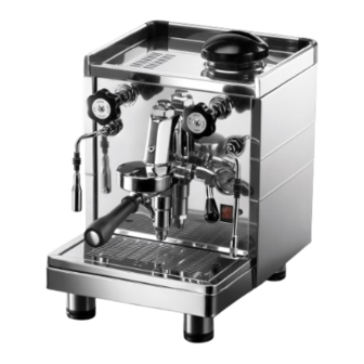
Page 8: Technical Characteristics
Technical characteristics Internal components VERSION 1GR ROSSO C:0 M:100 Y:100 K:0 NERO C:0 M:0 Y:0 K:100 VERDE C:100 M:0 Y:100 K:0 Water tank. Steam knob. Pressure gauge. Machine main switch. Anti-burn rubber. Coffee dispensing lever. Steam dispensing nozzle. Boiler heating element indicator light working. - Page 9 VERSION 2GR EMA ROSSO C:0 M:100 Y:100 K:0 NERO C:0 M:0 Y:0 K:100 VERDE C:100 M:0 Y:100 K:0 Water tank. Steam Knob. Hot water dispensing knob. Coffee dispensing lever. Coffee dispensing spout. Hot water dispensing nozzle. Steam dispensing nozzle. Adjustable foot. Anti-burn rubber.
-
Page 10: Internal Components
Internal components VERSIONS 1GR EMA-EPU-EVD ROSSO C:0 M:100 Y:100 K:0 NERO C:0 M:0 Y:0 K:100 VERDE C:100 M:0 Y:100 K:0 Boiler. Electronic control unit. Water tank (*). Volumetric dosing device. Boiler pressure gauge. Dispensing group. Drain pad. Internal vibration pump. Internal motorpump (*). - Page 11 VERSION 2GR EMA ROSSO C:0 M:100 Y:100 K:0 NERO C:0 M:0 Y:0 K:100 VERDE C:100 M:0 Y:100 K:0 Water tank. Electronic control unit. Boiler. Dispensing group. Drain pad. Pressure gauge. Vibration pump. Solenoid valve. Technical manual...
-
Page 12: Push Button Panel Mininova 1Gr Version Evd
Push button panel Mininova 1GR Version EVD Large 1 espresso coffee ROSSO C:0 M:100 Y:100 K:0 NERO C:0 M:0 Y:0 K:100 VERDE C:100 M:0 Y:100 K:0 PROG. STOP Stop/ espressos Large Program. coffees Technical data The nameplate of the machine is fixed on the base of the frame under the drain pan. -
Page 13: Preparation
Preparation Unpacking the machine Open the packaging, ensuring not to damage the machine. Remove the machine protections and the equipment contained in the package. Take the machine out. ROSSO C:0 M:100 Y:100 K:0 If there is an external motor pump, the motor and the NERO C:0 M:0 Y:0 K:100 VERDE... -
Page 14: Equipment Preparation
Equipment preparation Motor pump (only for version 1GR) For the machines with an external motor, it is Softener necessary to prepare the pump and the motor. On request, an automatic resin softener is supplied. Assemble the 3/8 gas connection with the inlet filter For further information, refer to chapter "Softeners". -
Page 15: Machine Installation
Machine installation ROSSO C:0 M:100 Y:100 K:0 NERO C:0 M:0 Y:0 K:100 VERDE C:100 M:0 Y:100 K:0 Positioning contact with the operator. Prepare an ample support base for the machine that is suitable to support its weight (13); It is important for In case of installation of the machine in motion all terminals of connections to the water mains (8) and environments (ships, trains, etc.) it's necessary... -
Page 16: Hydraulic Connection (With Hydraulic Connection Available)
Warnings Hydraulic connection (version with hydraulic connection available) The water supply must provide cold water for human consumption (potable water) at a pressure If the machine is available to be connected up to the between 1,5 and 5 bars. If the pressure is higher than water, follow the instructions below: 5 bar, connect a pressure reducer before the pump. -
Page 17: Hydraulic Connection (With Inner Tank)
Hydraulic connection (version with The water supply of the appliance must be carried inner tank) out with water which is suitable for human In inner tank version the operations consumption, in compliance with the regulations in of connection to the aqueduct are not force in the place of installation. - Page 18 To restore the level of liquid is sufficient to remove the tank cover and add water. It is recommended to clean the tank periodically as follow: Extract the tank from its housing; carefully wash the tank with lukewarm water; fill the tank with potable water; place the tank correctly in place.
-
Page 19: Conversion From Tank To Water Mains 1Gr Version
Conversion from TANK to WATER MAINS 1GR Version Through this procedure you can change the type of water supply of the machine, from internal Tank to Water Mains. All operations must be performed by technical personnel only. ROSSO C:0 M:100 Y:100 K:0 • Unplug the machine from the power supply. -
Page 20: Conversion From Water Mains To Tank 1Gr Version
Conversion from WATER MAINS to TANK 1GR Version Through this procedure you can change the type of water supply of the machine, from Water Mains to internal Tank. All operations must be performed by technical personnel only. ROSSO C:0 M:100 Y:100 K:0 • Unplug the machine from the power supply. -
Page 21: Conversion From Tank To Water Mains 2Gr Version
Conversion from TANK to WATER MAINS 2GR Version Through this procedure you can change the type of water supply of the machine, from internal Tank to Water Mains. All operations must be performed by technical personnel only. ROSSO C:0 M:100 Y:100 K:0 • Unplug the machine from the power supply. -
Page 22: Conversion From Water Mains To Tank 2Gr Version
Conversion from WATER MAINS to TANK 2GR Version Through this procedure you can change the type of water supply of the machine, from Water Mains to internal Tank. All operations must be performed by technical personnel only. ROSSO C:0 M:100 Y:100 K:0 • Unplug the machine from the power supply. -
Page 23: Wiring
Wiring Machine start-up It is necessary to link a safety main After getting equipped the water supply to the switch (A) on the electric panel, as required machine, turn the machine on using the main switch of by standard regulations. the machine (1). -
Page 24: External Motor Pump Adjustment
3.10 3.11 External motor pump adjustment Machine tune-up (only version 1GR with external When installation is complete, the appliance has to be started, brought to the nominal working condition and motor pump) left for 30 minutes in the "ready to operate" condition. To adjust operating pressure proceed as follows: Afterwards, the appliance has to be turned off and • Operate a coffee delivery switch;... -
Page 25: Boilers
Boilers Control of the pressure in the boiler The boiler is constructed in steel (1) (version 1GR) Versions EMA - EPU: or copper sheet metal (version 2GR) , to which the The pressure switch (1) makes it possible to control heat exchangers (3) are assembled which in turn are boiler pressure by activating or bypassing the heating connected to the delivery group. -
Page 26: Coffee Delivery Groups
Coffee delivery groups Electronic control unit (version EVD) The electronic control unit is installed on the machines The delivery group and the heat exchanger are with volumetric dosing. Its function is to the fundamental components in obtaining espresso manage electronically the dose of coffee coffee,in particular, the function of the group is the through the passage of the water in to coffee erogation. -
Page 27: Pumping System
Pumping system Pressure switch This is a component that feeds the machine, raising The pressure switch makes it the water pressure to 8-9 bar for coffee delivery and possible to control boiler pressure automatic filling of the boiler. by activating or bypassing the Depending on the whether the machine is equipped heating element in the boiler. -
Page 28: Anti-Flooding Device
15.4 BY - PASS valve Anti-flooding device It's a valve used in the versions with vibration pump. LThe cover installed on the It makes it possible to reduce the pressure of water pressure relief valve makes it from the vibration pump. possible to collect any water which may leak from the boiler due a malfunction and channel... -
Page 29: Hot Water Dispensing Nozzle
Hot water dispensing nozzle Softener The hot water dispensing nozzle is connecterd to a 18.1 Description suction pipe of the boiler. Depending on the model, the hot water dispensing Mains water contains insoluble salts, which cause the may occur in two ways: build-up of lime scale deposits in the boiler and other • Manual: regolation by rotation of the knob on the parts of the machine. -
Page 30: Technical Data
18.3 18.4 Setting by-pass Technical data Depending on the hardness of the water, set by-pass Model of the softener as indicated in the table below. Example: Connecting fitting 3/8" 3/8" 3/8" 3/8" Water hardness 9°dKH type Water supply pressure min.-max. (bar) Setting by-pass 2 Water temperature ROSSO... -
Page 31: Softener
Softener The build-up of lime scale deposits in the hydraulic circuit and boiler inhibits thermal exchange, thus Alternatively to water filter, a resins softener can be compromising proper operation of the machine. used. Heavy incrustation of the boiler may cause long This component has the ability to retain calcium in machine shutdowns and invalidate the warranty the water. -
Page 32: Descaling
Descaling This procedure is designed for use with liquid descaling "PULYDESCALER espresso". 20.1 1GR Version If the machine is in "Water Mains", mode, it must be ROSSO C:0 M:100 Y:100 K:0 switched to internal tank see paragraph 3.5: NERO C:0 M:0 Y:0 K:100 VERDE C:100 M:0 Y:100 K:0 • Turn on the machine and bring it to working condi-... -
Page 33: 2Gr Version
20.2 2GR Version If the machine is in "Water Mains", mode, it must be switched to internal tank see paragraph 3.7: • turn on the machine and bring it to working condi- tion: the gauge should show a pressure of 1-1.2 bar; • place under all coffee spouts a large pitcher and make sure the levers of the groups (F) are closed;... -
Page 34: Cleaning
Cleaning Cleaning For perfect cleaning and efficiency of the appliance, BODY several simple cleaning operations are necessary on Cleaning of panels with a cloth moistened with luke- the functional parts and accessories as well as the body warm water. Remove the tray and Cup holder Grill and panels. -
Page 35: Checks And Maintenance
Checks and maintenance When cleaning, always use cloths that are completely clean and hygienic. To guarantee the To ensure perfect safety and efficiency of the machine correct operation and hygiene of the hot beverages over time, it is necessary to carry out maintenance. In dispenser, it is necessary to use the cleaning particular, it is advisable to carry out an overall check methods and products suitable for this purpose. - Page 36 Checks Checks SAFETY OR PRESSURE RELIEF VALVE SOFTENER 1) first try : The formation of limescale in the hydraulic circuit of • remove the top grill of the machine; the machine indicates that regeneration has been • use pliers to pull the pin (6) upwards; ROSSO C:0 M:100 Y:100 K:0 neglected.
-
Page 37: Malfunctions And Related Solutions
Malfunctions and related solutions MALFUNCTION CAUSE SOLUTION The general switch is in the "O" position Place the general switch in the "1" position The machine switch is defective Replace the main switch MACHINE LACKING POWER The mains power switch supply is in "OFF" Place the main power switch in "ON"... - Page 38 MALFUNCTION CAUSE SOLUTION The temperature of the boiler is too high Reduce the pressure in the boiler by turning the pressure switch with the screw(versions EMA-EPU) COFFEE IS TOO HOT The flow reducer of the group is unsuitable Replace the regulator with a smaller diameter one Coffee is ground too coarsely Adjust the grinding of the coffee COFFEE DISPENSED TOO QUICKLY...
- Page 39 MALFUNCTION CAUSE SOLUTION Lime scale and mineral build-ups in the pump Check the status of the pump and replace it, if have caused it to jam necessary THE MOTOR STOPS SUDDENLY OR THE The pump and motor are not aligned (only with Install the motor-pump joint motorpump) THERMAL PROTECTOR INTERVENES DUE...
-
Page 40: List Of Hazards
If you should decide not to use the appliance List of hazards It is necessary to shut it down by disconnecting the power supply cable from the electrical mains, closing the This chapter describes possible hazards for the user if inflow of water from the hydraulic mains and emptying the specific safety standards (described in this manual) the hydraulic system. -
Page 41: Section Ii - Electrical/Hydraulic Diagrams
ROSSO C:0 M:100 Y:100 K:0 NERO C:0 M:0 Y:0 K:100 VERDE C:100 M:0 Y:100 K:0 Section II - ELECTRICAL/HYDRAULIC diagrams Technical manual... -
Page 42: Electrical Schemes
Electrical schemes 25.1 Electrical scheme versions1GR EMA-EPU ROSSO C:0 M:100 Y:100 K:0 NERO C:0 M:0 Y:0 K:100 VERDE C:100 M:0 Y:100 K:0 R (L1) R (L1) R (L1) N (L2) N (L2) N (L2) CAL Boiler DEV Diverter EVC Boiler fill solenoid valve Phase Main switch 120V... -
Page 43: Electrical Scheme Version 1Gr Evd
25.2 Electrical scheme version 1GR EVD ROSSO C:0 M:100 Y:100 K:0 NERO C:0 M:0 Y:0 K:100 VERDE C:100 M:0 Y:100 K:0 10 9 8 7 6 5 4 3 2 1 R (L1) R (L1) R (L1) N (L2) N (L2) N (L2) CAL Boiler EVA Solenoid valve A.E.A. -
Page 44: Electrical Scheme Version 2Gr
25.3 Electrical scheme version 2GR ROSSO C:0 M:100 Y:100 K:0 NERO C:0 M:0 Y:0 K:100 VERDE C:100 M:0 Y:100 K:0 IGR2 IGR1 R (L1) R (L1) R (L1) N (L2) N (L2) N (L2) CAL Boiler DEV Diverter EVC Boiler fill solenoid valve Phase F1 Fuse entries (10A) IG Main switch... -
Page 45: Hydraulic Schemes
Hydraulic schemes 26.1 Hydraulic scheme 1GR ROSSO C:0 M:100 Y:100 K:0 NERO C:0 M:0 Y:0 K:100 VERDE C:100 M:0 Y:100 K:0 1 Water tank 14 Pressure gauge A Version Vibration pump 2 Water entry filter 15 Safety valve Aqueduct 3 Motorpump/Vibration pump 16 Antidepression valve EVD Version EVD 4 Pressure pump regolation... -
Page 46: Hydraulic Scheme 2Gr
26.2 Hydraulic scheme 2GR ROSSO C:0 M:100 Y:100 K:0 NERO C:0 M:0 Y:0 K:100 VERDE C:100 M:0 Y:100 K:0 1 Water tank 14 Coffee exchanger 2 Water entry filter 15 Anti - depressione valve 3 Tap 16 Safety valve 4 Water supply entry 17 Bottleneck 5 Non return valve 18 Group solenoid valve... - Page 48 WEGA MACCHINE PER CAFFÈ S.r.l. Via Condotti Bardini, 1 - 31058 SUSEGANA (TV) - ITALY Tel. +39.0438.1884811 - Fax +39.0438.1884890 www.wega.it - info@wega.it Cod. 02000442 - Rev. 03 - 03/2016...
Need help?
Do you have a question about the Mininova and is the answer not in the manual?
Questions and answers