Table of Contents

Related Manuals for Wega URBAN EVDP


Summary of Contents for Wega URBAN EVDP
- Page 1 FONDO VERDE CHIARO PANTONE 376C URBAN LOGO VERDE SCURO PANTONE 348C EVDP FONDO VERDE CHIARO C:56; M:0; Y:100; K:0 LOGO VERDE SCURO C:100; M:0; Y:79; K:28 ESPRESSO COFFEE MACHINE Use and Maintenance Manual. TECHNICIANS' instructions.
- Page 2 IMPORTANT: Read carefully before use. Store for future reference. All rights reserved on contents The total or partial reproduction and the dissemination of this document’s contents is forbidden without the Manufacturer’s prior written authorisation. The Company logo is owned by the Manufacturer of the Machine.
- Page 3 URBAN SAFETY PRECAUTIONS the following paragraphs as they cannot be eliminated: I.I. LEVEL OF TRAINING AND Compliance with the installation and ma- chine’s safety standards is dependent on the KNOWLEDGE REQUIRED OF THE use, installation, maintenance and correct op- TECHNICIAN eration of the machine.
- Page 4 URBAN I.IV. INSTALLATION able to carry out operations when the machine is not powered, the Technician must apply the Electrical hazard rules prescribed by current technical standards (disconnect the power supply, avoid reclosures, High temperature hazard check that there is no voltage, etc.). Risk of explosion MAINTENANCE AND CLEANING I.V.
- Page 5 URBAN Only perform the maintenance and cleaning EMERGENCY SITUATIONS I.VI. operations indicated in this manual. Should an emergency situation occur as a result If the problem cannot be resolved, switch off of a machine malfunction, adopt the measures the machine and contact the Manufacturer. provided for in the emergency plan posted in All maintenance operations must be carried the premises and in any case, proceed to imme-...
-
Page 6: Table Of Contents
URBAN General contents WI-FI CONNECTION ............52 INTRODUCTION ..............7 MAINTENANCE AND CLEANING .........53 Guidelines for reading the Manual ........7 10.1 Safety precautions ..............53 Storing the Manual ..............7 10.2 PPE features ................53 Method for updating the Instruction Manual ....7 10.3 Maintenance ................53 Recipients ..................7 Glossary and Pictograms ............8 10.4 Water filter maintenance ............56... -
Page 7: Introduction
URBAN 1. INTRODUCTION 1.2 Storing the Manual The Instruction Manual must be stored carefully. The manual Read this manual carefully. It provides important safety infor- should be stored, handled with care with clean hands and not mation to the Technician regarding the operations indicated placed on dirty surfaces. -
Page 8: Glossary And Pictograms
URBAN RECIPIENT QUALIFICATIONS Personal protective equipment (PPE) The machine is intended for a professional non-generalised Clothing or equipment worn by someone to protect their use, therefore the Technician must: health or safety. • Have attended the training courses organised by the Man- Intended use ufacturer relating to the type of machine;... -
Page 9: Guarantee
2.3 The manufacturer’s customer safety. support service WEGA MACCHINE PER CAFFÈ S.R.L. Via Condotti Bardini, 1 31058 SUSEGANA (TV) - ITALY Tel. +39.0438.1799700 - Fax +39.0438.1884890 Email: info@wega.it - Website: www.wega.it... -
Page 10: Intended Use
URBAN 2.4 Intended use General safety features The Technician must be aware of accident risks, safety devices The espresso coffee machine has been designed to profes- and the general safety rules set forth in EU directives and by sionally prepare hot beverages such as tea, cappuccinos and the legislation of the country where the machine is installed. -
Page 11: Machine Diagram
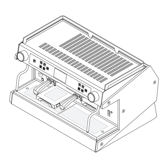
URBAN 2.5 Machine diagram Pushbutton panel 10. Display touch screen Steam knob 11. Cup holder grille Steam nozzle 12. USB port Hot water nozzle 13. Cup warmer shelf ON switch 14. Illuminated side panels Adjustable foot 15. Steam nozzle/automatic steam wand (if fitted) Pull-out cup holder grille 16. -
Page 12: Internal Components
URBAN 2.7 Internal components Steam heating unit safety pressure switch Steam heating unit heating element Steam heating unit Internal motor pump (if included) Coffee heating unit pressure switch Water inlet connection Hot water mixing system Drain tray Dispensing group 10. Volumetric dosing device 11. -
Page 13: Data And Ce Marking
An example of a nameplate is provided below: MARCHIO COMMERCIALE WEGA MACCHINE PER CAFFÈ S.r.l. Via C. Bardini,1 SUSEGANA (TV) - ITALY Tel. +39.0438.1799700 Fax +39.0438.1884890 S/N: Mod. - Page 14 URBAN 2.8.1 Coffee heating unit 2.8.3 Dispensing group Each dispensing group is fitted with a thermally-insulated cof- The dispensing group (A) is made up of a metallic block which fee heating unit (1) for dispensing hot water for coffees. is hooked onto the coffee heating unit (B). Heat is provided by an elec- The functions of the group are summarised as follows: tric heating element (2).
- Page 15 URBAN 2.8.4 Electronic control unit 2.8.7 Automatic Water Entry The electronic control unit is the machine’s The Automatic Water Entry system is designed to check the “brain”, since it monitors and controls the ap- water level in the heating unit. It consists of: pliance’s full operation.
- Page 16 URBAN 2.8.8 Pressure switch 2.8.11 Expansion valve + check valve The machine has two types of pressure switches: This is a valve consisting of an expansion valve and a check valve. • COFFEE HEATING UNIT PRESSURE SWITCH Each coffee heating unit is equipped with a pressure • Expansion valve (A): switch to adjust the pressure.
- Page 17 URBAN 2.8.13 Cup warmer 2.8.14 Cappuccino maker (optional) The cup warmer device warms the cups before they are used. The cappuccino maker can be installed as an optional extra onto a steam nozzle or installed directly onto the tap itself. This device can both heat and froth the milk.
- Page 18 URBAN 2.8.15 Automatic steam wand (optional) This system automatically froths milk at the programmed temperature. The operating principle is listed below: • Select the desired button on the display, e.g. the but- ton. • The solenoid valve opens (2) which consequently allows the steam to flow from the heating unit to the automatic steam wand nozzle (9).
-
Page 19: Transport And Handling
URBAN 3. TRANSPORT AND HANDLING 2.8.16 Water filter In the mains water, non-soluble salts are present which cause limestone to form in 3.1 Safety precautions the heating unit and other parts of the machine. Carefully read the instructions provided in chapter Drinking water can also contain heavy "I. -
Page 20: Unpacking The Machine
URBAN 4. STORAGE 3.5 Unpacking the machine Only remove the machine from its packaging when it is ready 4.1 Overview to be installed, in order to prevent accidental collisions which could damage it: In the waiting period prior to installation, the machine must •... -
Page 21: Installation
URBAN 5. INSTALLATION 5.4 Installation and operation spaces Before the machine arrives, a suitable environment must be 5.1 Safety precautions prepared: • The appliance is not suitable for installation in an area Carefully read the instructions provided in chapter where a water jet may be used. "I. -
Page 22: Support Base
URBAN 5.5 Support base To ensure a sufficient degree of ergonomics and machine Support base safety, a support base with the following features must be Grinder-dispenser made available (reference drawings on the next page): 50 cm minimum distance between the machine and the •... - Page 23 URBAN TECHNICIANS' manual...
-
Page 24: Drilling The Support Base
URBAN 5.6 Drilling the support base If holes need to be drilled into the support base to let the wa- ter inlet hoses, outlet hoses and power cables pass through, follow the directions given in the drawings below. 2 GROUPS 200 mm Front of the machine 536 mm... -
Page 25: Hydraulic Connection
URBAN 5.7 Hydraulic connection Before connecting the hydraulic system, make sure the appliance has been disconnected from the electrical mains. 5.7.1 Water supply The appliance’s water supply must provide water which is suitable for human consumption, and must conform with the regulations in force in the place of installation. - Page 26 URBAN FOR THE EUROPEAN COMMUNITY: when con- • Connect the motor pump cable (with the smaller cross- necting to a water mains or an external tank, a section) to the connector of the external motor as shown non-return valve (12) must be positioned upstream in the diagram below.
-
Page 27: Commissioning
URBAN 6. COMMISSIONING 6.4 External motor pump adjustment To adjust the operating pressure, proceed as follows: 6.1 Safety precautions • Press a coffee dispensing switch. Carefully read the instructions provided in chapter • Adjust the pressure by turning the screw located on the "I. -
Page 28: Turning The Machine On And Off
URBAN 6.6 Turning the machine on and off After start-up, the machine is ready to dispense coffee, and the display will show the screen below. An orange steam icon During the machine's heating-up phase, the nega- indicates that it is necessary to wait a few minutes for the tive pressure valve will release steam for a few sec- steam to be dispensed. -
Page 29: Water Renewal
URBAN 7. MACHINE INFORMATION 6.7 Water renewal When the machine is being installed, the Technician must re- The machine information is available on the display: place the water inside the hydraulic circuits by following these • Select the bar on the right side of the display; steps: •... -
Page 30: Parameter Programming
URBAN 8. PARAMETER PROGRAMMING 8.1.1 Access via the USB Stick • Insert the specific USB stick into the reader (12). This paragraph shows all of the programming menus where the various machine functions can be set. • Select the bar on the right side of the display; All these operations are carried out via the touchscreen dis- •... - Page 31 URBAN 8.1.2 Access via Password User-resettable parameters: (code 3 on the memory stick) PARAMETER NO. DESCRIPTION • Select the bar on the right side of the display; UNITS OF MEASUREMENT PRESSURE MEASUREMENT • Select the menu button VOLUME MEASUREMENT • Select the service settings button •...
-
Page 32: Energy Saving Management
URBAN 8.2 Energy Saving Management Three "Energy Saving" operating modes are available: • : manual activation • : programmed operation • : self-learning management To turn off the machine or activate the Energy Saving mode, Manual proceed as follows: Scheduled •... -
Page 33: Manually Activating The Energy Saving Mode
URBAN 8.3 Manually activating the ENERGY SAVING mode To manually put one or more dispensing groups in standby, follow these steps: • Access the menu (see para. 8.1). • Select the standby button for the groups. • Select the dispensing group or groups to put in standby. -
Page 34: User Configuration Menu
URBAN 8.4 User Configuration Menu 8.4.1 ENERGY SAVING setup in PROG mode With the Energy Saving system in mode, proceed with the following steps to programme the standby and idle cycle for the week: • Access the menu (see para. 8.1). • Select the configuration button •... - Page 35 URBAN 8.4.2 BEVERAGE DOSE programming To programme coffee and hot water doses, proceed as fol- lows: • Access the menu (see para. 8.1); • Select the configuration button • Press the dose programme button • Select the dispensing group; • Select the desired dose button (e.g. “1 espresso” •...
- Page 36 URBAN 8.4.3 SERVICE PARAMETER programming To adjust the parameters of some of the machine’s services, proceed as follows: • Access the menu (see para. 8.1). • Select the configuration button • Press the button. • Select the button of the parameter to be modified. •...
- Page 37 URBAN 8.4.4 DATE and TIME settings To set the date and time on the machine, proceed as follows: • Access the menu (see para. 8.1). • Select the configuration button • Press the button. • Select the button of the information you would like to modify.
- Page 38 URBAN 8.4.5 COFFEE BLEND selection To set the machine according to the type of coffee blend used, proceed as follows: • Access the menu (see para. 8.1). • Select the configuration button • Press the button. • Select the desired blend button, e.g. •...
-
Page 39: Screensaver Configuration
URBAN 8.5 SCREENSAVER configuration To set the display screensaver, proceed as follows: • Access the menu (see para. 8.1). • Select the configuration button • Press the button. • To set how long after the machine’s last operation to acti- vate the screensaver, select the button. - Page 40 URBAN 8.5.1 CLOUD configuration To set up the machine’s cloud, proceed as follows: • Access the menu (see para. 8.1). • Select the configuration button • Press the button. • Select the button. • Use the keyboard to enter the information in the various fields (Street, City, Postcode, County, Country).
- Page 41 URBAN 8.5.2 BEVERAGE COUNTER list To view the beverages dispensed by the machine, proceed as follows: • Access the menu (see para. 8.1). • Select the configuration button • Press the button. • Use the buttons to scroll through the various pages and view the counts.
- Page 42 URBAN 8.5.3 Service Settings Menu A-B-C maintenance cycles ---------------------reset You can access the machine’s full programming mode from Date of the next maintenance -----------------set date 1 | Maintenance report Water consumption (L) ------------------------reset the two menu pages. Burr wear (kg) ----------------------------------reset The following is a summary diagram of the programming sec- Energy saved (kWh) ----------------------------reset tions, the parameters involved and the operations envisaged.
- Page 43 URBAN 8.5.4 Maintenance report The following information can be viewed in this section: • Type A maintenance cycles; • Type B maintenance cycles; • Type C maintenance cycles; • Water consumption (litres); • Burr wear (kg); • Energy saved (kWh). To reset the data to zero, select the button.
- Page 44 URBAN 8.5.5 Service tuning The parameters regarding machine services can be set up in this section, such as: • Heating unit pressure; • Temperature of the heating unit in energy saving mode; • Cup warmer temperature; • Heating unit pressure during the boost phase; •...
- Page 45 URBAN 8.5.6 Washes In this section you can programme the automatic wash cycles and the wash management: • Viewing the date of the last wash; • Enable the automatic wash; • Enable the automatic wash at each start-up; • Set the number of wash cycles; •...
- Page 46 URBAN 8.5.7 Checking the dispensing cycle 8.5.8 Coffee tuning In this section of the programming mode, you can enable In this section some coffee dispensing parameters can be set, which information is displayed while doses are being dis- such as: pensed: •...
- Page 47 URBAN 8.5.9 Parameter list All the machine’s parameters can be programmed in this sec- tion. Use the buttons or the display keyboard to edit the information. To go from one page to another, select the button. The complete list of all parameters is provided in chap.
- Page 48 URBAN 8.5.10 Maintenance thresholds This section is dedicated to managing the machine’s main- tenance: • Type A-B-C maintenance threshold; • Viewing the remaining cycles until the A-B-C threshold; • Viewing the next date for the A-B-C maintenance thresh- old; • Days remaining until maintenance; •...
- Page 49 URBAN 8.5.11 USB Use the USB memory stick to update the machine’s software and upload useful information, such as: • Updating the keypad/display software; • Update the control unit software; • Upload slides; • Import parameters; • Save parameters; • Set the language; •...
- Page 50 URBAN 8.5.12 Heating unit efficiency The efficiency of the heating units can be checked in this sec- tion. Comparing the various parameters over time, allows you to evaluate the operating status of the heating units: For each heating unit, press the “test” button to test the effi- ciency of the heating unit whilst heating up.
- Page 51 URBAN 8.5.13 Delete Splash images 8.5.14 Restoring the parameters This item allows you to delete customer-personalised screens In this section, you can restore the initial programming data, by restoring the default ones. such as: • Restoring the user parameters; To cancel, select the button.
-
Page 52: Wi-Fi Connection
URBAN 9. WI-FI CONNECTION If the Wi-Fi service is set up on the machine, it can be con- nected as follows: • Check if the writing which appears on the low- er-right of the display, is inside a white rectangle; •... -
Page 53: Maintenance And Cleaning
URBAN 10. MAINTENANCE AND CLEANING 10.1 Safety precautions Carefully read the instructions provided in chapter "I. SAFETY PRECAUTIONS" on page 3. 10.2 PPE features When installing the machine, the following PPE is required: The use of protective gloves is mandatory. 10.3 Maintenance 10.3.1 Scheduled maintenance Perform the following maintenance according to the specified... - Page 54 URBAN Component Type of operation Quarterly Yearly Replace the electric heating element if it becomes faulty or malfunctions. Do not replace the heating element with a more powerful one. Before mak- ing any changes, please contact the Manufacturer. If the thermostat of the heating element is triggered, reset it by pressing the central button of the thermostat.
- Page 55 URBAN 10.3.2 Maintenance after a short period 10.3.5 SAFETY VALVE check of machine inactivity The pressure relief valve is one of the main components for machine safety. Therefore, it is important to carry out the fol- “Short period of machine inactivity” refers to a period of time lowing checks: exceeding one working week.
-
Page 56: Water Filter Maintenance
URBAN 10.4 Water filter maintenance 10.4.2 Bypass configuration Depending on the hardness of the water, adjust the bypass of 10.4.1 Determining the water hardness the water filter as shown in the table below. Example: As part of the filter maintenance, it is advisable to test the 9°dKH water hardness water beforehand. - Page 57 URBAN 10.4.3 Technical data Model Connection 3/8" 3/8" 3/8" 3/8" coupling type Min.-max. water supply pressure (bar) Water temperature 4-30 4-30 4-30 4-30 min. - max. (°C) Room temperature 4-40 4-40 4-40 4-40 min-max (°C) Total height (A) without bracket (mm) Total height (B) with bracket (mm)
-
Page 58: Water Softener Regeneration
URBAN 10.5 Water softener regeneration In order to keep the water softener, and hence the machine, in perfect operating condition, it is necessary to regularly re- It is very important to regenerate the softener within the es- generate it, depending on the softener and hardness of the tablished times. -
Page 59: Malfunctions And Solutions
URBAN 10.6 Malfunctions and solutions Problem Cause Action The main switch is in the "OFF" position. Turn the main switch to the ON position. The machine switch is faulty. Replace the main switch. NO MACHINE POWER The mains switch is in the OFF position. Turn the mains switch to the ON position. - Page 60 URBAN Problem Cause Action There are steam pockets in the dispensing Reduce the water temperature. THE CUP IS DIRTY system. Check the cause and resolve the problem. WITH SPLASHES OF COFFEE There are air pockets in the hydraulic circuit. Adjust the grinder as appropriate. The coffee has been ground too coarsely.
-
Page 61: Cleaning Operations
URBAN 10.7 Cleaning operations 10.7.2 Washing the cappuccino maker Take special care when cleaning the cappuccino maker and 10.7.1 General instructions follow the steps provided below: A few simple cleaning tasks are required to have a perfectly • Perform an initial wash by immersing the suction hose sanitised and efficient appliance. - Page 62 URBAN 10.7.4 Scheduled dispensing group wash If provided, the machine automatically requests that the dis- pensing groups be washed on a daily basis. To begin the washing cycle, proceed as shown on the display. You can always cancel the washing request and resume nor- mal operation.
-
Page 63: Spare Parts
URBAN 10.7.6 Cleaning the group shower screen, 10.7.7 Cleaning the steam nozzle/auto- shower screen containment ring matic steam wand and filter holder Weekly Clean the steam nozzle as follows: Daily • Insert the nozzle into a jug with water and a specific Clean the dispensing group and filter holder shower screens cleaner, in accordance with the manufacturer's instruc- with the supplied brush on a daily basis. -
Page 64: Disassembly
URBAN 13. DISASSEMBLY 14. DISPOSAL To disassemble the machine, follow the installation procedure 14.1 Disposal information in reverse order - see chap. 5. For the European Union and the European Economic Area All dismantled components must be divided by material to only. -
Page 65: Wiring Diagrams
URBAN 15. WIRING DIAGRAMS 15.1 ELECTRIC MAINS connection GNYE (*) Per il Brasile CAVO A 3 CONDUTTORI (Fase+Neutro+Terra) Phase Phase Phase Neutral GNYE Earth Blue Power cable Grey GNYE Yellow-green Brown Black CAVO A 4 CONDUTTORI (3 Fasi+Terra) GNYE CAVO A 5 CONDUTTORI (3 Fasi+Neutro+Terra) To correctly connect the machine to the electric mains, please refer to the information provided on the nameplate (see the example in paragraph 2.8). -
Page 66: Electronic Control Unit Diagram
URBAN 15.2 Electronic control unit diagram CN26 CN25 DL17 DL12 DL11 DL10 CN44 +3,3V DL21 CN45 DL20 DL22 CN41 CN46 CN43 CN24 RL10 CN23 RL11 CN15 TRF1 +12V ISO CN17 CN42 CN18 TR10 CN19 CN13 DL23 TR11 CN16 CN22 TECHNICIANS' manual... - Page 67 URBAN Fuse Description 5x20 time-delay fuse, 6.3 A Protects: from RL1 to RL13 5x20 T 10 A fuse Protects: the group 2 coffee heating unit heating element 5x20 T 10 A fuse Protects: the group 3 coffee heating unit heating element 5x20 T 10 A fuse Protects: the group 1 coffee heating unit heating element 5x20 T 10 A fuse...
-
Page 68: Connector Wiring Diagram
URBAN 15.3 Connector wiring diagram Heating element connection for groups 1 and 3 CN19 NTC cup warmer connection CN22 Heating element connection for groups 2 and 4 Wiring of the circuit board Heating element connection for the steam heating unit CN23 Connection of 230 VAC outputs CN23A Connection of 230 VAC outputs... -
Page 69: Control Unit Connection Diagram
URBAN 15.4 Control unit connection diagram E.V. CN26 CN25 E.V. CN24 E.V. E.V. LFD LFS LLA CN23 CN22 E.V. E.V. E.V. A1 A2 E.V. AUTOST. A1 A2 Orange Left side panel LEDs Work surface LED power supply Power indicator Side panel + logo LED power supply Brown White Frame mass... - Page 70 URBAN CN1 - Group 1 and 3 coffee heating unit heating element connec- tion Orange White/Blue White Blue White/Brown White/Black CN2 - Group 2 and 4 coffee heating unit heating element connec- Volumetric dosing device tion Automatic steam wand SV EVgr Group SV Heating unit-filling SV...
- Page 71 URBAN CN13 - RS232 serial socket connection Orange RX IN White/Blue CN13 TX OUT White Blue White/Brown White/Black CN15 - NTC temperature sensor connection Volumetric dosing device Automatic steam wand SV NTc1 +NTc1 EVgr Group SV NTg1 Heating unit-filling SV +NTg1 NTc3 EVt1 Hot water SV...
- Page 72 URBAN CN22 - Circuit board wiring Orange White/Blue CN22 White Blue White/Brown CN23 - Connection of 230 VAC outputs White/Black On/O LPL Volumetric dosing device Automatic steam wand SV EVt2 EVgr Group SV Heating unit-filling SV CN23 EVt1 Hot water SV On/O LF EVt2 Hot water SV 2 Frothing SV...
-
Page 73: Control Unit Connection Diagram -Ul
URBAN 15.5 Control unit connection diagram -UL- E.V. CN26 CN25 E.V. CN24 E.V. E.V. LFD LFS LLA CN23 CN22 E.V. E.V. E.V. E.V. AUTOST. CCAS 230V Orange 1 A Fuse Rear logo LED ALARM Light-up logo LED power supply 1 A Fuse Brown Work surface LED power supply 15 A Class C Fuse... - Page 74 URBAN CN1 - Group 1 and 3 coffee heating unit heating element connection -UL- Orange White/Blue White Blue White/Brown White/Black Volumetric dosing device CN2 - Group 2 and 4 coffee heating unit heating element Automatic steam wand SV connection -UL- EVgr Group SV Heating unit-filling SV...
- Page 75 URBAN CN13 - RS232 serial socket connection -UL- RX IN Orange CN13 TX OUT White/Blue White Blue White/Brown CN15 - NTC temperature sensor connection -UL- White/Black NTc1 Volumetric dosing device +NTc1 NTg1 Automatic steam wand SV +NTg1 EVgr Group SV NTc3 Heating unit-filling SV +NTc3...
- Page 76 URBAN CN22 - Circuit board wiring -UL- Orange CN22 White/Blue White Blue CN23 - Connection of 230 VAC outputs -UL- White/Brown White/Black Volumetric dosing device CN23 Automatic steam wand SV On/O LF EVgr Group SV Heating unit-filling SV EVt1 Hot water SV EVt2 Hot water SV 2 EVm Mixed water SV CN24 - Connection of 230 VAC outputs -UL-...
-
Page 77: Display Control Unit Diagram
URBAN 15.6 DISPLAY control unit diagram CN41 Control unit Display CN40 CN41 DIP2 Set up DIP1 and DIP2 as shown in the figure. DIP1 Push button panel connection diagram Set up the various Dip Switches as shown in the figure. TECHNICIANS' manual... -
Page 78: Hydraulic Diagram
URBAN 16. HYDRAULIC DIAGRAM 15 16 15 16 TEA outlet MANUAL tap STEAM outlet COLD nozzle MIXED TEA adjustment solenoid valve MAINS filter HOT WATER solenoid valve VOLUMETRIC dosing device STEAM heating unit safety pressure switch SCNR valve HEATING UNIT LEVEL probe PUMP pressure transducer SAFETY LEVEL probe HEATING UNIT FILLING solenoid valve... -
Page 79: Credit - Debit/Debit - Credit System
URBAN 17. CREDIT - DEBIT/DEBIT - CREDIT Communication protocol SYSTEM Description of the operating principle with reference to the diagram shown below: • Order the beverage at the till. 17.1 CREDIT - DEBIT system with direct • Select the ordered dose on the coffee machine. connection to the till •... -
Page 80: Debit - Credit System With Direct
URBAN 17.2 DEBIT - CREDIT system with direct Communication protocol Description of the operating principle with reference to the connection to the till diagram shown below: The DEBIT-CREDIT system allows beverages to be paid for • Select the desired dose on the coffee machine. after they have been dispensed, as the doses are registered •... -
Page 81: Beverage Selection Code Table
URBAN 18. PARAMETER TABLE 17.3 Beverage selection code table Par. Description min. Def. MAX. UM Description Signal Temperature unit of measurement °C °C °F 1 GR1 Espresso 011 h (0 = °C, 1 = °F) 1 GR1 Long 013 h Pressure unit of measurement 0 = bar, 1 = Atm, 2 = kPa 2 GR1 Espressos... - Page 82 URBAN Par. Description min. Def. MAX. UM Par. Description min. Def. MAX. UM Buzzer sound disabled when LCD Group 4 coffee heating unit setpoint °C keypad buttons are pressed Delta temperature in standby 0 = Buzzer works normally Minimum coffee heating unit tem- °C perature.
- Page 83 URBAN Par. Description min. Def. MAX. UM Par. Description min. Def. MAX. UM Setpoint temperature for closing the P126 Board setpoint temperature °C steam solenoid valve and cancelling Temperature differential for resump- the warning for the user regarding °C P127 °C tion from alarm steam escaping, when the steam...
- Page 84 URBAN Par. Description min. Def. MAX. UM Par. Description min. Def. MAX. UM P166 Coffee heating unit deep standby Parity for the RS485 CN32 serial °C setpoint temperature 0 = None (with 2 stop bits) P167 Steam heating unit deep standby °C P302 1 = ODD (1 stop bit)
- Page 85 URBAN Par. Description min. Def. MAX. UM Par. Description min. Def. MAX. UM P364 Cup warmer heating element power P622 Long coffee dose time - Group 3 60.0 P365 Pump motor power P623 Double short coffee dose time - Group 3 60.0 P400 Period for sending data to the Cloud 9999...
- Page 88 WEGA MACCHINE PER CAFFÈ S.r.l. Via Condotti Bardini, 1 - 31058 SUSEGANA (TV) - ITALY Tel. +39.0438.1799700 - Fax +39.0438.1884890 www.wega.it - info@wega.it Cod. WY02000717 - Rev. 04 - 03/2021...
Need help?
Do you have a question about the URBAN EVDP and is the answer not in the manual?
Questions and answers