Table of Contents
Advertisement
Quick Links
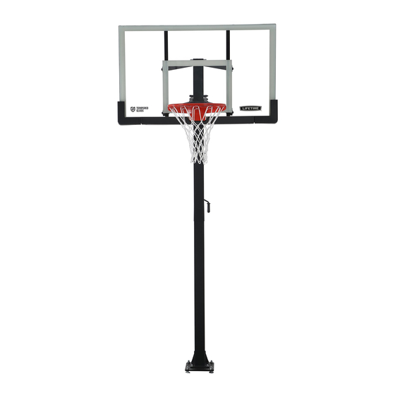
CRANK ADJUST
BASKETBALL SYSTEM
MODEL 90569
BEFORE ASSEMBLY:
• Assembly requires at least eight 80-lb. bags of
concrete mix. Before digging, call to locate any
buried utility lines.
• 3+ people recommended for setup.
GET ASSEMBLY HELP
WATCH THE INSTRUCTIONAL VIDEOS ON YOUTUBE
Scan the code, or search http://go.lifetime.com/90569playlist
TOOLS REQUIRED
Carpenter's Level
1/2" (x2)
5/16"
(x1, included)
QUESTIONS?
CONTACT LIFETIME CUSTOMER SERVICE:
Call: 1-800-225-3865
7:00 am-5:00 pm (Monday-Friday) MST
and 9:00 am-1:00 pm Saturday MST
®
Shovel
3/4" (x2)
3/8"
(x1, included)
Live Chat: www.lifetime.com
(click on "Live Chat" tab)
Video Instructions:
www.youtube.com/lifetimeproducts
ASSEMBLY INSTRUCTIONS
Pour le français, voir la page 2. Para el español, ver la página 3.
Save this instruction in the event
that the manufacturer has to be
contacted for replacement parts.
Tape Measure
Cement
(80 lb bag x 8)
9/16" (x2)
Electric Drill
Rubber Mallet
For Customer Service in Mainland
Europe and the United Kingdom,
E-mail: cs@lifetimeproducts.eu
TABLE OF CONTENTS
Icon Legend................................2
Notices....................................3
Initial Setup...............................4
Pole Assembly.............................7
Extension Arm Assembly............10
Handle Assembly......................14
Backboard to Rim Assembly........17
Backboard to Pole Assembly.......24
Final Assembly..........................27
Maintenance Instructions..........32
Registration........................33
Warning Sticker........................34
Warranty................................35
Model Number: 90569
Product ID:
Advertisement
Table of Contents

Related Manuals for Lifetime CRANK ADJUST 90569


Summary of Contents for Lifetime CRANK ADJUST 90569
-
Page 1: Table Of Contents
• 3+ people recommended for setup. GET ASSEMBLY HELP WATCH THE INSTRUCTIONAL VIDEOS ON YOUTUBE Save this instruction in the event that the manufacturer has to be Scan the code, or search http://go.lifetime.com/90569playlist contacted for replacement parts. TOOLS REQUIRED TABLE OF CONTENTS Icon Legend........2 Notices........3... -
Page 2: Icon Legend
ICON LEGEND • Indicates special heed should be taken when reading. • Indicates the parts to be used for a section. • Indicates no parts required for a specifi c section. • Indicates the hardware to be used for a section. •... -
Page 3: Notices
WARNINGS & NOTICES SAFETY INSTRUCTIONS FAILURE TO FOLLOW THESE WARNINGS MAY RESULT IN SERIOUS INJURY OR PROPERTY DAMAGE AND WILL VOID WARRANTY. Owner must ensure that all players know and follow these rules for safe operation of the system. To ensure safety, do not attempt to assemble this product without following the instructions carefully. Check entire box and inside all packing material for parts and/or additional instruction material. -
Page 4: Initial Setup
INITIAL SETUP HARDWARE REQUIRED Hardware Blister Pack AE0 (x1) CYV (x1) AOE (x8) PARTS REQUIRED Metal Parts AEZ (x4) AEI (x4) AKT (x1) TOOLS REQUIRED 3/4" Carpenter’s Level Shovel Cement / Cemento Ciment Tape Measure (x2) (80 lb bag x 8) - Page 5 SECTION 1 (CONTINUED) TOOLS AND HARDWARE REQUIRED 3/4” (x2) AOE (x8) • Dig a hole 30” (76.2 cm) deep and 21” (53 cm) square. The edge of the hole should be flush with the edge of the playing court. If you live in an area where frost heaves may pose a problem, consult your local building inspector to determine the appropriate hole depth.
- Page 6 SECTION 1 (CONTINUED) TOOLS AND HARDWARE REQUIRED (80-lb Bag x 8) • If you are using concrete mix, mix the concrete • Center the Template (AKT) over the hole. Insert the according to the instructions on the bags. Please J-Bolts (AEI) into the concrete and agitate the Template note that a thicker mix of concrete will dry stronger.
-
Page 7: Pole Assembly
POLE ASSEMBLY HARDWARE REQUIRED Hardware Blister Pack CMV (x1) CUB (x2) EJH (x4) EJG (x2) ELW (x1) PARTS REQUIRED Large Parts ALH (x1) ALE (x1) EJS (x2) TOOLS REQUIRED 9/16" (x1) 5/16" (x1, included) Electric Drill... - Page 8 TOOLS AND HARDWARE REQUIRED • If you have trouble with this section, scan the QR code to view a video on how to assemble the Pole. • http://go.lifetime.com/crankadjustpole • Slide the flared end of the Top Pole (ALH) onto • Raise the pole assembly about 12 inches off to the swaged end of the Bottom Pole (ALE).
- Page 9 SECTION 2 (CONTINUED) TOOLS AND HARDWARE REQUIRED EJG (x2) 9/16" 5/16" CUB (x2) CMV (x1) EJH (x4) • Use an electric drill to secure the Top Pole to the Bottom Pole using a Self-Tapping Screw (CMV). You may need to use a hex driver or chuck the Self-Tapping screw directly into an electric drill.
-
Page 10: Extension Arm Assembly
EXTENSION ARM ASSEMBLY HARDWARE REQUIRED Hardware Blister Pack EJM (x2) CUB (x1) CUG (x2) CYF (x2) EJL (x1) AOQ (x1) AEG (x4) DIQ (x4) PARTS REQUIRED Metal Parts AKD (x2) AKE (x1) TOOLS REQUIRED 3/4" 9/16" Rubber Mallet 3/8" (included) 5/16"... - Page 11 • If you have trouble with this section, scan the code below to view a video on its assembly. • http://go.lifetime.com/crankadjustarms • Secure the Lower Extension Arm Assembly (AKE) through the first set of holes on the Pole above the Handle Brackets.
- Page 12 SECTION 3 (CONTINUED) TOOLS AND HARDWARE REQUIRED 9/16" 5/16" EJL (x1) CUB (x1) EJM (x2) • Install the Bolt (EJL) through the Pole with a long Rubber Spacer (EJM) on either side. Make sure the back end of the Extension Arm Assembly remains beneath this hardware.
- Page 13 SECTION 3 (CONTINUED) TOOLS AND HARDWARE REQUIRED 3/4" 3/8" CUG (x1) DIQ (x2) AEG (x2) CYF (x1) • Attach the Upper Extension Arms (AKD) to the Pole as shown.
-
Page 14: Handle Assembly
HANDLE ASSEMBLY HARDWARE REQUIRED Hardware Blister Pack AEG (x4) CUG (x1) DIQ (x2) EJQ (x1) CYF (x2) PARTS REQUIRED Large Parts ELX (x1) TOOLS REQUIRED 3/4" 3/8"... - Page 15 • If you have trouble with this section, scan the code below to view a video on its assembly. • http://go.lifetime.com/crankadjusthandle • Align the Spacer at the top of the Crank Adjust Assembly (ELX) with the holes in the Lower Extension Arms. Secure...
- Page 16 SECTION 4 (CONTINUED) TOOLS AND HARDWARE REQUIRED 3/4" EJQ (x1) 3/8" DIQ (x2) AEG (x2) CYF (x1) • Install the hardware indicated in the location shown. Make sure the Large Plastic Spacers (DIQ) are placed between the Crank Adjust Assembly and the Pole Brackets.
-
Page 17: Backboard To Rim Assembly
BACKBOARD TO RIM ASSEMBLY HARDWARE REQUIRED Hardware Blister Pack 5 9/16” ANM (x2) ANL (x1) ANJ (x2) ADX (x2) BGZ (x1) ELG (x2) ANK (x4) ABB (x2) ABK (x4) ANN (x2) ABD (x8) AAX (x1) PARTS REQUIRED Glass and Metal Parts AJI (x1) - Page 18 BACKBOARD TO RIM ASSEMBLY PARTS REQUIRED Metal Parts BPZ (x1) AMK (x1) BGY (x1) BQA (x1) AMA (x1) ALY (x1) ANO (x1) AMB (x1) AMC (x1) ALX (x1) TOOLS REQUIRED 1/2” 9/16” 3/4”...
-
Page 19: Parts Identifier
PARTS IDENTIFIER This page intentionally left blank... - Page 20 PARTS IDENTIFIER Parts shown at 10% of Actual Size ALH (x1) ALE (x1) EJS (x2) Parts shown at 25% of Actual Size Metal Parts BPZ (x1) AMK (x1) BGY (x1) BQA (x1) AMA (x1) ALY (x1) ANO (x1) AMB (x1) AMC (x1) ALX (x1)
- Page 21 PARTS IDENTIFIER Parts shown at 5% of Actual Size AEZ (x4) AEI (x4) AKZ (x1) AJI (x1) AKT (x1) ELX (x1) Metal Parts AKD (x2) AKE (x1) HARDWARE BAG AND BLISTER PACK IDENTIFIER...
- Page 22 PARTS IDENTIFIER This page intentionally left blank...
- Page 23 • If you have trouble with this section, scan the code below to view a video on its assembly. • http://go.lifetime.com/crankadjustbackboardtorim • Lay the Backboard (AJI) face up with the Rim holes exposed over the edge of a table. Place the Rim Impact Spacer (BGY) in the Backboard.
- Page 24 SECTION 5 (CONTINUED) TOOLS AND HARDWARE REQUIRED 5 9/16” ABK (x2) ANL (x1) ABD (x4) AAX (x1) ANK (x2) ELG (x2) • Secure the Rim Adapter Plate (ALY) to the Backboard (AJI) by using the hardware as shown. • Only fi nger-tighten this hardware for now.
- Page 25 SECTION 5 (CONTINUED) TOOLS AND HARDWARE REQUIRED ANM (x2) ABB (x2) ANK (x2) • Slide the Spring Holder Clevis (AMK) onto the Eye Bolt (BQA) and secure with the hardware shown. • Only fi nger-tighten this hardware for now.
- Page 26 SECTION 5 (CONTINUED) TOOLS AND HARDWARE REQUIRED 9/16” 1/2” BGZ (x1) ANN (x2) 3/4” • Slide the Compression Spring (BGZ) onto the Eye Bolt (BQA), and secure with the hardware shown. Tighten the 3/8” Zinc Nuts (ANN) to adjust Rim tension. ANO (x1) •...
- Page 27 SECTION 5 (CONTINUED) TOOLS AND HARDWARE REQUIRED ADX (x2) • Attach the Rim Cover Plate (AMA) to the Rim with the hardware shown.
-
Page 28: Backboard To Pole Assembly
BACKBOARD TO POLE ASSEMBLY HARDWARE REQUIRED Hardware Blister Pack EKM (x4) CUB (x4) EJH (x12) PARTS REQUIRED NO NEW PARTS ARE REQUIRED FOR THIS SECTION TOOLS REQUIRED 9/16" 5/16"... - Page 29 TO PREVENT SERIOUS INJURIES, THE POLE SHOULD BE HELD DOWN BY AT LEAST ONE ADULT AT ALL TIMES. • If you have trouble with this section, scan the code below to view a video on its assembly. • http://go.lifetime.com/crankadjustbackboardtopole • Attach the Lower Extension Arms (AKE) to the Backboard (AJI) using the hardware shown.
- Page 30 SECTION 6 (CONTINUED) TOOLS AND HARDWARE REQUIRED 9/16” 5/16" EKM (x2) CUB (x2) EJH (x6) • Attach the Upper Extension Arm (AKD) to the Backboard (AJI) using the hardware shown. • Repeat step 6.2 to attach the remaining Upper Extension Arm to the Backboard.
-
Page 31: Final Assembly
FINAL ASSEMBLY HARDWARE REQUIRED Hardware Blister Pack AQN (x4) AOR (x4) ADM (x4) AQO (x4) PARTS REQUIRED • DO NOT PROCEED with this Section until 7.5' the concrete from Section 1 has been allowed to cure at least 72 hours (3 days). 8.5' AKZ (x1) 9.5'... - Page 32 SECTION 7 (CONTINUED) TOOLS AND HARDWARE REQUIRED 3/4” AQN (x4) DO NOT PROCEED WITH THIS SECTION UNTIL THE CONCRETE FROM SECTION 1 HAS BEEN ALLOWED TO CURE AT LEAST 72 HOURS (3 DAYS). • Stack a Star Washer (AQN) onto the exposed ends of the J-Bolts (AEI). •...
- Page 33 SECTION 7 (CONTINUED) TOOLS AND HARDWARE REQUIRED • Position the Pole so the slots in the plate at the bottom of the Pole align with the two J-Bolts closest to the playing surface. Push the plate against the Bolts, ensuring the slots are aligned exactly with the Bolts. With the system adjusted to its lowest position, have at least three adults slowly and carefully lift the Pole so the Bolts slide through the slots.
- Page 34 SECTION 7 (CONTINUED) TOOLS AND HARDWARE REQUIRED 3/4” ADM (x4) AOR (x4) • At least two people should support the Pole A MINIMUM OF THREE ADULTS ARE REQUIRED FOR THIS STEP. as one person slides a 1/2” Washer (AOR) onto •...
- Page 35 SECTION 7 (CONTINUED) TOOLS AND HARDWARE REQUIRED AQO (x4) • Place a Plastic Cap (AQO) onto each J-Bolt. • Tighten the four Hex Nuts (ADM) on top of the pole plate until they are secure against the plate, ensuring the Backboard remains vertical. Turn the center Hex Bolt (AEO) until it is flush against the pole plate.
-
Page 36: Maintenance Instructions
MAINTENANCE INSTRUCTIONS / ENSAMBLAJE DEL ARMAZÓN / ASSEMBLAGE DE LA CHARPENTE The life of your basketball system depends on many variables. The climate, exposure to corrosives such as salt, pesticides, or herbicides, and excessive use or misuse can all contribute to Pole failure, which may cause property damage or personal injury. Check your basketball system frequently for loose hardware, excessive wear, and signs of corrosion. -
Page 37: Registration
. And you can rest assured that Lifetime ® will not sell or provide your personal data to other third parties, or allow them to use your personal data for their own purposes. We invite you to read our privacy policy at www.lifetime.com REGISTER today! -
Page 38: Warning Sticker
Son mécanisme a été conçu uniquement pour soutenir le poids du panneau et de l’anneau. N’accrochez rien au manche, à l’anneau, au panneau ni aux leviers sous peine d’endommager l’équipement et d’annuler la garantie. Lifetime Products, Inc., Clearfield, UT 84016 www.lifetime.com 7/12/2016 # 1176611... - Page 39 3. This warranty is nontransferable and is expressly limited to the repair or replacement of defective product. If the product is defective within the terms of this warranty, Lifetime Products, Inc. will repair or replace defective parts at no cost to the purchaser.
- Page 40 ® ENHANCE YOUR LIFETIME PURCHASE BY ADDING ACCESSORIES OR OTHER GREAT PRODUCTS ® To purchase accessories or other Lifetime products, visit us at: www.lifetime.com Or call: 1-800-424-3865 7:00 am–5:00 pm (M–F) MST and 9:00 am–1:00 pm Saturday MST www.lifetime.com © 2019...
Need help?
Do you have a question about the CRANK ADJUST 90569 and is the answer not in the manual?
Questions and answers