Johnson Controls DSH024C Series Installation Operation & Maintenance
Air-cooled self-contained units, horizontal r-410a air conditioning units c generation smart equipment controller
Hide thumbs
Also See for DSH024C Series:
- Installation, operation & maintenance instructions manual (36 pages) ,
- Installation manual (64 pages) ,
- Installation manual (24 pages)
Table of Contents
Advertisement
Advertisement
Table of Contents

Related Manuals for Johnson Controls DSH024C Series


Summary of Contents for Johnson Controls DSH024C Series
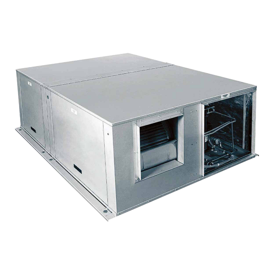
- Page 1 AIR-COOLED SELF-CONTAINED UNITS INSTALLATION, OPERATION, MAINTENANCE Supersedes: 145.32-IOM5 (818) Form 145.32-IOM5 (419) MODEL DSH024C–120C HORIZONTAL R-410A AIR CONDITIONING UNITS C GENERATION SMART EQUIPMENT CONTROLLER LD2897 Issue Date: April 8, 2019...
- Page 2 FORM 145.32-IOM5 ISSUE DATE: 04/08/2019 IMPORTANT! READ BEFORE PROCEEDING! GENERAL SAFETY GUIDELINES This equipment is a relatively complicated apparatus. which it is situated, as well as severe personal injury or During rigging, installation, operation, maintenance, death to themselves and others at the site. or service, individuals may be exposed to certain com- This document is intended for use by owner-authorized ponents or conditions including, but not limited to:...
- Page 3 FORM 145.32-IOM5 ISSUE DATE: 04/08/2019 CHANGEABILITY OF THIS DOCUMENT In complying with the manufacturer's’ policy for con- lifting, and operating/service personnel should verify tinuous product improvement, the information con- whether the equipment has been modified and if current tained in this document is subject to change without literature is available from the owner of the equipment notice.
- Page 4 FORM 145.32-IOM5 ISSUE DATE: 04/08/2019 NOMENCLATURE 1, 2 3 4, 5, 6 H 120 C MISCELLANEOUS PRODUCT CATEGORY OPTIONS DS = Integral Air-Cooled A = None Packaged A/C, R-410A D = Condensate Overflow Switch PRODUCT IDENTIFIER H = Horizontal, Ceiling Mounted HEATING OPTIONS 0 = None NOMINAL CAPACITY...
-
Page 5: Table Of Contents
FORM 145.32-IOM5 ISSUE DATE: 04/08/2019 TABLE OF CONTENTS SECTION 1 – INSTALLATION ..........................9 Pre-Installation Inspection of Equipment ......................9 Rigging ..............................9 Installation Site ............................... 10 Location ..............................10 Cabinet Configuration Options ........................10 Unit Mounting ..............................10 Separation of the Units ........................... 11 Separating the Units ..........................12 Interconnecting Refrigerant Tubing ........................ - Page 6 FORM 145.32-IOM5 ISSUE DATE: 04/08/2019 SECTION 2 – STARTUP AND OPERATION ......................39 Checking Superheat and Subcooling ....................39 Startup (Cooling) ...........................40 Microprocessor Controller ..........................41 Temperature Sensors ..........................41 USB Port ...............................41 LCD Display ............................41 Safety Monitoring ..........................41 Low Ambient ............................41 Anti-Short Cycle Delay (ASCD) Protection ....................
- Page 7 FORM 145.32-IOM5 ISSUE DATE: 04/08/2019 LIST OF FIGURES FIGURE 1 - Securing Straps and Brackets ......................10 FIGURE 2 - Self-Sealing Refrigerant Couplings...................... 11 FIGURE 3 - Packaged Unit With Couplings ......................12 FIGURE 4 - Single Compressor Unit – Typical Installation Configuration ............... 13 FIGURE 5 - Dual Compressor Unit –...
- Page 8 FORM 145.32-IOM5 ISSUE DATE: 04/08/2019 THIS PAGE INTENTIONALLY LEFT BLANK.
-
Page 9: Section 1 - Installation
FORM 145.32-IOM5 ISSUE DATE: 08/30/2018 SECTION 1 – INSTALLATION Models 2–8 tons can be ordered as packaged, factory- PRE-INSTALLATION INSPECTION OF charged unitized packages, or as factory-split. The 10 EQUIPMENT ton model comes factory-split. All units are factory tested to ensure safe operation and quality assembly. -
Page 10: Installation Site
FORM 145.32-IOM5 SECTION 1 – INSTALLATION ISSUE DATE: 04/08/2019 INSTALLATION SITE S The unit is factory-split and factory-charged with Lock all electrical power supply switches in R-410A refrigerant. The unit comes with refrig- the off position before installing the unit. erant shut-off/coupling valves that hold charge Failure to disconnect the power supply may in both the condenser and evaporator sections. -
Page 11: Separation Of The Units
FORM 145.32-IOM5 SECTION 1 – INSTALLATION ISSUE DATE: 04/08/2019 TABLE 1 - OPERATING WEIGHT UNIT OPERATING SHIPPING WEIGHT WEIGHT (CONDENSER (CONDENSER ONLY) ONLY) DSH024C 675 (390) 715 (430) DSH036C 680 (400) 720 (440) DSH048C 955 (568) 1015 (608) DSH060C 995 (593) 1065 (633) DSH096C 1470 (815) -
Page 12: Separating The Units
FORM 145.32-IOM5 SECTION 1 – INSTALLATION ISSUE DATE: 04/08/2019 4. For 2–5 ton models, cut the refrigerant line sections between the pairs of shut-off valves. It is recommended to make this cut where accessi- bility is greatest - in the condensing section of the unit. -
Page 13: Figure 4 - Single Compressor Unit - Typical Installation Configuration
FORM 145.32-IOM5 SECTION 1 – INSTALLATION ISSUE DATE: 04/08/2019 Horizontal Ductable Ceiling Air Conditioner Packaged Installation Top Joining Strip Condenser Evaporator Section Section Exhaust Outdoor Side Cross-Member Angle Air Intake Ceiling Horizontal Ductable Ceiling Air Conditioner Split Installation Condenser Section Evaporator Section Supply Return... -
Page 14: Figure 5 - Dual Compressor Unit - Typical Installation Configuration
FORM 145.32-IOM5 SECTION 1 – INSTALLATION ISSUE DATE: 04/08/2019 Horizontal Evaporator Section Ductable Ceiling Air Conditioner Packaged Installation Supply Air Condenser Section Exhaust Ceiling Return Air Outdoor Air Floor Intake Horizontal Ductable Ceiling Air Conditioner Split Installation Condenser Section Evaporator Section Ceiling Supply Air Floor... -
Page 15: Interconnecting Refrigerant Tubing
FORM 145.32-IOM5 SECTION 1 – INSTALLATION ISSUE DATE: 04/08/2019 When brazing couplings, ensure the following: The following guidelines apply to field fabricated piping: 1. When applying paste flux to the copper tube, • Use hard drawn refrigeration type copper tubing avoid applying excessive amounts. -
Page 16: Dimensional Data
FORM 145.32-IOM5 SECTION 1 – INSTALLATION ISSUE DATE: 04/08/2019 DIMENSIONAL DATA 4.75 Front 7.00 17.50 26.00 1.00 Evaporator Condenser Fan Access Fan Access Condenser Openings Evaporator Section Condenser Section Electrical Box Access Electrical Box Access Electrical Power Low Voltage Connection Connection 25.63 2.70... -
Page 17: Figure 7 - Dsh048C And Dsh060C Dimensional Data: 4-5 Ton Horizontal A/C Unit
FORM 145.32-IOM5 SECTION 1 – INSTALLATION ISSUE DATE: 04/08/2019 4.75 10.12 17.50 28.00 1.00 Front Evaporator Condenser Fan Access Fan Access Condenser Openings Evaporator Section Condenser Section Electrical Box Access Electrical Box Access Low Voltage Electrical Power Connection Connection 29.38 15.00 3.00 9.73... -
Page 18: Figure 8 - Dsh096C Dimensional Data: 8 Ton Horizontal A/C Unit
FORM 145.32-IOM5 SECTION 1 – INSTALLATION ISSUE DATE: 04/08/2019 112.00 1.25 80.00 1.00 Evaporator Section Compressor Section 25.00 17.00 4.75 Electrical Box Access Electrical Box Access Compressor Condenser Evaporator Condenser Opening Access Panel Blower Drive Blower Drive Access Panel Access Panel Front View 85.21 Filter Access... -
Page 19: Figure 9 - Dsh120C Dimensional Data: 10 Ton Horizontal A/C Unit
FORM 145.32-IOM5 SECTION 1 – INSTALLATION ISSUE DATE: 04/08/2019 60.88 70.88 84.00 Power Evaporator Section Connection 4.70 Compressor Section 1.25 48.20 Electrical Box Electrical Box Access Access Evaporator Blower Drive Condenser Blower Condenser Service Hose Condenser Discharge Access Panel Drive Access Panel Access Panel Access Front View... -
Page 20: Typical Service Clearances
FORM 145.32-IOM5 SECTION 1 – INSTALLATION ISSUE DATE: 04/08/2019 Typical Service Clearances Front Evaporator Condenser Fan Access Fan Access 4 Inch Minimum Clearance (for Drain Trap) 36 Inch Minimum Clearance Return Air Condenser Intake Condenser Section Evaporator Section Condenser Discharge Supply Air 36 Inch Minimum Clearance LD27701... -
Page 21: Figure 11 - 8 And 10 Ton Horizontal A/C Unit Service Clearances
FORM 145.32-IOM5 SECTION 1 – INSTALLATION ISSUE DATE: 04/08/2019 Back View 4 Inch Minimum Clearance (for Drain Tap) Condenser Intake 36 Inch Minimum Clearance Condenser Evaporator Section Section Return Air Condenser Evaporator Section Section Supply Air 36 Inch Minimum Clearance 36 Inch Minimum Clearance Top View... -
Page 22: Unit Corner Weights
FORM 145.32-IOM5 SECTION 1 – INSTALLATION ISSUE DATE: 04/08/2019 Unit Corner Weights Condenser Supply Air Discharge Condenser Evaporator Condenser Return Air Intake POINT WEIGHTS (LBS) TOTAL UNIT OPERATING SHIPPING 2 Ton 3 Ton 4 Ton 1010 5 Ton 1060 8 Ton 1470 1560 LD27703... -
Page 23: Ductwork
FORM 145.32-IOM5 SECTION 1 – INSTALLATION ISSUE DATE: 04/08/2019 As a general rule, these velocities require DUCTWORK an intake louver sized approximately 1.25 When installing ductwork, adhere to local codes. to 1.5 times the dimensions of the duct Where possible, minimize duct runs and avoid abrupt connection on the unit, and a discharge changes in direction. -
Page 24: Packaged Unit
FORM 145.32-IOM5 SECTION 1 – INSTALLATION ISSUE DATE: 04/08/2019 Packaged Unit LOW VOLTAGE WIRING If the unit is installed as a packaged unit, the thermo- For low voltage thermostat wiring, an 18 gauge wire can stat (low voltage) wiring and power wiring are brought be used for up to 100 foot lengths. -
Page 25: Figure 15 - Typical Control Diagram For Three Stage Cooling (Dsh096C)
FORM 145.32-IOM5 SECTION 1 – INSTALLATION ISSUE DATE: 04/08/2019 Main Control Thermostat Terminal Block Terminals Optional field installed jumper is required if desired to change the unit logic to a two stage cooling operation Common 24V Input Optional Condensate Overflow Switch Standard Jumper SD–24 (If No Options) -
Page 26: Figure 16 - Typical Control Diagram For Three Stage Cooling (Dsh120C)
FORM 145.32-IOM5 SECTION 1 – INSTALLATION ISSUE DATE: 04/08/2019 Main Control Thermostat Terminal Block Terminals Optional field installed jumper is required if desired to change the unit logic to a two stage cooling operation Common 24V Input Optional Condensate Overflow Switch SD–24 Standard Jumper (If No Options) -
Page 27: Table 4 - Electrical Data - Standard Evaporator Motor
FORM 145.32-IOM5 SECTION 1 – INSTALLATION ISSUE DATE: 04/08/2019 TABLE 4 - ELECTRICAL DATA – STANDARD EVAPORATOR MOTOR EVAP. COND. COMPRESSOR #1 COMPRESSOR #2 FUSE/ MODEL # VOLTAGE CCT. BKR. LRA QTY RLA LRA 208- DSH024C2 55.4 12.83 230/3/60 208- DSH036C2 10.4 0.75... -
Page 28: Fan Performance
FORM 145.32-IOM5 SECTION 1 – INSTALLATION ISSUE DATE: 04/08/2019 TABLE 6 - ELECTRICAL DATA – OVERSIZED CONDENSER MOTOR EVAP. COND. COMPRESSOR #1 COMPRESSOR #2 FUSE/ MODEL # VOLTAGE CCT. BKR. LRA QTY RLA LRA 208- DSH120C2 16.2 58.95 230/3/60 DSH120C4 460/3/60 27.9 DSH120C5... -
Page 29: Table 10 - Dsh024C - Condenser Fan Performance
FORM 145.32-IOM5 SECTION 1 – INSTALLATION ISSUE DATE: 04/08/2019... -
Page 30: Table 13 - Dsh060C - Supply Air Blower Performance
FORM 145.32-IOM5 SECTION 1 – INSTALLATION ISSUE DATE: 04/08/2019... -
Page 31: Table 16 - Dsh096C - Condenser Fan Performance
FORM 145.32-IOM5 SECTION 1 – INSTALLATION ISSUE DATE: 04/08/2019... -
Page 32: Motor And Pulley Data
FORM 145.32-IOM5 SECTION 1 – INSTALLATION ISSUE DATE: 04/08/2019 MOTOR AND PULLEY DATA TABLE 19 - EVAPORATOR – STANDARD BLOWER MOTOR AND DRIVE DATA ADJUSTABLE MOTOR MOTOR FIXED BLOWER PULLEY BELTS PULLEY DRIVE MODEL RANGE PITCH BROWNING PITCH BROWNING FRAME EFFICIENCY RATING/ (RPM) -
Page 33: Table 21 - Condenser - Standard Blower Motor And Drive Data
FORM 145.32-IOM5 SECTION 1 – INSTALLATION ISSUE DATE: 04/08/2019 TABLE 21 - CONDENSER – STANDARD BLOWER MOTOR AND DRIVE DATA ADJUSTABLE MOTOR MOTOR FIXED BLOWER PULLEY BELTS PULLEY DRIVE MODEL RANGE PITCH BROWNING PITCH BROWNING FRAME EFFICIENCY RATING/ (RPM) DIAMETER PART DIAMETER PART... -
Page 34: Blower Speed Adjustment
FORM 145.32-IOM5 SECTION 1 – INSTALLATION ISSUE DATE: 04/08/2019 BLOWER SPEED ADJUSTMENT Pulleys are adjustable only in half-turn incre- ments. For 4L and A belts, do not open the pulley Adjust the blower speed to increase or decrease the unit more than five full turns. -
Page 35: Figure 17 - Low Ambient Damper
FORM 145.32-IOM5 SECTION 1 – INSTALLATION ISSUE DATE: 04/08/2019 KIT # MODEL LADK-036C-1 DSH024B-C/036B-C 25.875 inches 5.0 inches 23.625 inches LADK-060C-1 DSH048B-C/060B-C 27.875 inches 5.0 inches 26.625 inches LADK-100C-1 DSH096B/C 48.0 inches 5.0 inches 29.25 inches LADK-120C-1 DSH120B/C 60.75 inches 5.0 inches 29.125 inches Low-Ambient... -
Page 36: Airside Economizer (Ase)
FORM 145.32-IOM5 SECTION 1 – INSTALLATION ISSUE DATE: 04/08/2019 AIRSIDE ECONOMIZER (ASE) Free Cooling Four types of free cooling options are available: dry Optional airside economizer mixing box is designed bulb changeover, single enthalpy, dual enthalpy to attach to the return air (RA) side of the evaporator. changeover, and auto. -
Page 37: Air Temperature Sensors
FORM 145.32-IOM5 SECTION 1 – INSTALLATION ISSUE DATE: 04/08/2019 AIR TEMPERATURE SENSORS VARIABLE FREQUENCY DRIVE (VFD) Each unit is equipped with standard SA temperature This section discusses variable frequency for only 8 and (SAT) and RAT sensors. Sensors ship inside the electri- 10 ton units. -
Page 38: Outdoor Fan Vfd (208-230V And 460V Only)
FORM 145.32-IOM5 SECTION 1 – INSTALLATION ISSUE DATE: 04/08/2019 The power (and optional low voltage wiring for trans- Mounted in the condenser corner post (or the special ducer) wiring can be found inside the VFD enclosure. enclosure for a field kit VFD), the VFD allows the No extra power wiring is required;... -
Page 39: Section 2 - Startup And Operation
FORM 145.32-IOM5 ISSUE DATE: 08/30/2018 SECTION 2 – STARTUP AND OPERATION Start the unit and check the rotation of fans and com- TABLE 24 - REFRIGERANT CHARGE (LBS) pressors. Scroll compressors only compress in one NUMBER OF UNIT CIRCUIT 1 CIRCUIT 2 rotational direction. -
Page 40: Startup (Cooling)
FORM 145.32-IOM5 SECTION 2 – STARTUP AND OPERATION ISSUE DATE: 04/08/2019 • Liquid Line Subcooling = Saturation Temperature Superheat (108.0°F) minus Liquid Line Temperature (95.0°) Only check superheat after establishing the steady state = 13.0°F operation of the unit, pulling down the discharge air tem- perature to within the control range, and running the unit Subcooling should be 10.0–14.0°F at design conditions. -
Page 41: Microprocessor Controller
FORM 145.32-IOM5 SECTION 2 – STARTUP AND OPERATION ISSUE DATE: 04/08/2019 8. Measure the evaporator fan motor's amp draw. Safety Monitoring The control monitors the following values: 9. Set the room thermostat fan switch to OFF. • Outdoor, supply, and return air temperatures 10. -
Page 42: Condensate Overflow Switch
FORM 145.32-IOM5 SECTION 2 – STARTUP AND OPERATION ISSUE DATE: 04/08/2019 Condensate Overflow Switch IntelliSpeed Supply Fan Control (8/10 Ton ™ Unit Only) A condensate overflow fault occurs when the conden- sate overflow switch opens for the first time, as the Setpoints and related data are shown in Table 27 . -
Page 43: Section 3 - Maintenance And Service
FORM 145.32-IOM5 ISSUE DATE: 08/30/2018 SECTION 3 – MAINTENANCE AND SERVICE Disconnect and lock out power when to the shaft and that the collar locking screw is properly servicing unit. Failure to do so may result set. Check that the blower wheel is tight on the shaft and in personal injury or death due to electri- that the hub set screws are properly torqued. - Page 44 FORM 145.32-IOM5 SECTION 2 – STARTUP AND OPERATION ISSUE DATE: 04/08/2019 THIS PAGE INTENTIONALLY LEFT BLANK.
-
Page 45: Appendix: Wiring Diagrams
FORM 145.32-IOM5 ISSUE DATE: 08/30/2018 APPENDIX: WIRING DIAGRAMS LD27712 FIGURE 21 - DSH024–060C HIGH VOLTAGE WIRING DIAGRAMS... -
Page 46: Figure 22 - Dsh096/120C High Voltage Wiring Diagrams
FORM 145.32-IOM5 APPENDIX: WIRING DIAGRAMS ISSUE DATE: 04/08/2019 LD27713 FIGURE 22 - DSH096/120C HIGH VOLTAGE WIRING DIAGRAMS... -
Page 47: Figure 23 - Dsh024-060C Low Voltage Wiring Diagrams
FORM 145.32-IOM5 APPENDIX: WIRING DIAGRAMS ISSUE DATE: 04/08/2019 LD28623 FIGURE 23 - DSH024–060C LOW VOLTAGE WIRING DIAGRAMS... -
Page 48: Figure 24 - Dsh0120C Low Voltage Wiring Diagrams
FORM 145.32-IOM5 APPENDIX: WIRING DIAGRAMS ISSUE DATE: 04/08/2019 LD28621_a FIGURE 24 - DSH0120C LOW VOLTAGE WIRING DIAGRAMS... - Page 49 FORM 145.32-IOM5 APPENDIX: WIRING DIAGRAMS ISSUE DATE: 04/08/2019 LD28621_b FIGURE 24 - DSH0120C LOW VOLTAGE WIRING DIAGRAMS (CONT'D)
-
Page 50: Figure 25 - Typical Airside Economizer Wiring Diagram
FORM 145.32-IOM5 APPENDIX: WIRING DIAGRAMS ISSUE DATE: 04/08/2019 LD27717 FIGURE 25 - TYPICAL AIRSIDE ECONOMIZER WIRING DIAGRAM... -
Page 51: R-410A Quick Reference Guide
FORM 145.32-IOM5 R-410A QUICK REFERENCE GUIDE ISSUE DATE: 04/08/2019 R-410A QUICK REFERENCE GUIDE Refer to the Section 1 – Installation for specific installation requirements. • R-410A refrigerant operates at 50–70% higher pressures than R-22. Ensure that servicing equipment and re- placement components are designed to operate with R-410A. - Page 52 Subject to change without notice. | Form 145.32-IOM5 (419) | Supersedes: 145.32-IOM5 (818) | All rights reserved. The Smart Equipment logo is a trademark of Johnson Controls in the United States and other countries. It is a part of the Johnson Controls product portfolio.
Need help?
Do you have a question about the DSH024C Series and is the answer not in the manual?
Questions and answers