Sign In
Upload
Manuals
Brands
Johnson Controls Manuals
Air Conditioner
DSH120C Series
Johnson Controls DSH120C Series Manuals
Manuals and User Guides for Johnson Controls DSH120C Series. We have
3
Johnson Controls DSH120C Series manuals available for free PDF download: Installation Manual, Installation Operation & Maintenance
Johnson Controls DSH120C Series Installation Operation & Maintenance (52 pages)
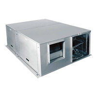
AIR-COOLED SELF-CONTAINED UNITS, HORIZONTAL R-410A AIR CONDITIONING UNITS C GENERATION SMART EQUIPMENT CONTROLLER
Brand:
Johnson Controls
| Category:
Air Conditioner
| Size: 4 MB
Table of Contents
Table of Contents
5
Section 1 - Installation
9
Pre-Installation Inspection of Equipment
9
Rigging
9
Installation Site
10
Location
10
Cabinet Configuration Options
10
Unit Mounting
10
FIGURE 1 - Securing Straps and Brackets
10
Separation of the Units
11
FIGURE 2 - Self-Sealing Refrigerant Couplings
11
TABLE 1 - Operating Weight
11
FIGURE 3 - Packaged Unit with Couplings
12
Separating the Units
12
TABLE 2 - Field Split Coupling Kits
12
FIGURE 4 - Single Compressor Unit - Typical Installation Configuration
13
FIGURE 5 - Dual Compressor Unit - Typical Installation Configuration
14
Interconnecting Refrigerant Tubing
15
TABLE 3 - Recommended Refrigerant Line Sizes
15
Dimensional Data
16
FIGURE 6 - DSH024C and DSH036C Dimensional Data: 2-3 Ton Horizontal A/C Unit
16
FIGURE 7 - DSH048C and DSH060C Dimensional Data: 4-5 Ton Horizontal A/C Unit
17
FIGURE 8 - DSH096C Dimensional Data: 8 Ton Horizontal A/C Unit
18
FIGURE 9 - DSH120C Dimensional Data: 10 Ton Horizontal A/C Unit
19
FIGURE 10 - 2-5 Ton Horizontal A/C Unit Service Clearances
20
Typical Service Clearances
20
FIGURE 11 - 8 and 10 Ton Horizontal A/C Unit Service Clearances
21
FIGURE 12 - Packaged Unit Installation
22
FIGURE 13 - Split Unit Installation
22
Unit Corner Weights
22
Ductwork
23
Louver Sizing Guidelines
23
Electrical Wiring
23
Packaged Unit
24
Split System
24
Low Voltage Wiring
24
Typical Wiring Schematics
24
FIGURE 14 - Typical Control Diagram for One and Two Stage Cooling
24
DSH048C, and DSH060C)
24
FIGURE 15 - Typical Control Diagram for Three Stage Cooling (DSH096C)
25
FIGURE 16 - Typical Control Diagram for Three Stage Cooling (DSH120C)
26
TABLE 4 - Electrical Data - Standard Evaporator Motor
27
TABLE 5 - Electrical Data - Oversized Evaporator Motor
27
Fan Performance
28
TABLE 6 - Electrical Data - Oversized Condenser Motor
28
TABLE 7 - DSH024C - Supply Air Blower Performance
28
TABLE 8 - DSH024C - Condenser Fan Performance
28
TABLE 9 - DSH036C - Supply Air Blower Performance
28
TABLE 10 - DSH024C - Condenser Fan Performance
29
TABLE 11 - DSH048C - Supply Air Blower Performance
29
TABLE 12 - DSH048C - Condenser Fan Performance
29
TABLE 13 - DSH060C - Supply Air Blower Performance
30
TABLE 14 - DSH060C - Condenser Fan Performance
30
TABLE 15 - DSH096C - Supply Air Blower Performance
30
TABLE 16 - DSH096C - Condenser Fan Performance
31
TABLE 17 - DSH120C - Supply Air Blower Performance
31
TABLE 18 - DSH120C- Condenser Fan Performance
31
Motor and Pulley Data
32
TABLE 19 - Evaporator - Standard Blower Motor and Drive Data
32
TABLE 20 - Evaporator - Oversized Blower Motor and Drive Data
32
TABLE 21 - Condenser - Standard Blower Motor and Drive Data
33
TABLE 22 - Condenser - Oversized Blower Motor and Drive Data
33
Blower Speed Adjustment
34
Adjusting the Blower Speed
34
Low Ambient Damper
34
FIGURE 17 - Low Ambient Damper
35
Airside Economizer (ASE)
36
Sequences of Operation
36
Air Temperature Sensors
37
Variable Frequency Drive (VFD)
37
Indoor Fan VFD
37
FIGURE 18 - RAT SAT Sensor
37
FIGURE 19 - Extension Wiring
37
Outdoor Fan VFD (208-230V and 460V Only)
38
Hot Gas Bypass (HGBP)
38
Section 2 - Startup and Operation
39
Checking Superheat and Subcooling
39
TABLE 23 - Pressure Switch Settings - All Models
39
TABLE 24 - Refrigerant Charge (Lbs)
39
Startup (Cooling)
40
TABLE 25 - R410A Pressure and Temperature Chart
40
Microprocessor Controller
41
Temperature Sensors
41
USB Port
41
LCD Display
41
Safety Monitoring
41
Low Ambient
41
Anti-Short Cycle Delay (ASCD) Protection
41
Fan Delays
41
Nuisance Trip Protection and Three Strikes
41
Lead-Lag
41
Condensate Overflow Switch
42
Operation
42
TABLE 26 - Compressor Control
42
TABLE 27 - Setpoints and Related Data
42
Section 3 - Maintenance and Service
43
Evaporator and Condenser Coils
43
Refrigerant Circuits
43
Blowers
43
Drive Belts
43
Filters
43
FIGURE 20 - Belt Tension Adjustment
43
TABLE 28 - Filter Sizes
43
Appendix: Wiring Diagrams
45
FIGURE 21 - DSH024-060C High Voltage Wiring Diagrams
45
FIGURE 22 - DSH096/120C High Voltage Wiring Diagrams
46
FIGURE 23 - DSH024-060C Low Voltage Wiring Diagrams
47
FIGURE 24 - DSH0120C Low Voltage Wiring Diagrams
48
FIGURE 25 - Typical Airside Economizer Wiring Diagram
50
R-410A Quick Reference Guide
51
Advertisement
Johnson Controls DSH120C Series Installation Manual (64 pages)
Air Conditioning Units C-Generation Smart Equipment Controller
Brand:
Johnson Controls
| Category:
Air Conditioner
| Size: 10 MB
Table of Contents
Table of Contents
3
General Safety Guidelines
5
Important
5
Read before Proceeding
5
Safety Symbols
5
Changeability of this Document
6
Associated Literature
7
Technical Support
7
Replacement Parts
7
Nomenclature
8
Installation
9
Pre-Installation Inspection of Equipment
9
Rigging
10
Installation Site
10
Location
10
Cabinet Configuration Options
10
Unit Mounting
11
Separation of the Units
12
Separating the Units
13
Interconnecting Refrigerant Tubing
17
Dimensional Data
19
Typical Service Clearances
23
Unit Corner Weights
25
Ductwork
26
Louver Sizing Guidelines
26
Electrical Wiring
27
Packaged Unit
27
Split System
27
Low Voltage Wiring
27
Typical Wiring Schematics
28
Fan Performance
32
Motor and Pulley Data
35
Blower Speed Adjustment
36
Adjusting the Blower Speed
36
Low Ambient Damper
36
Airside Economizer (ASE)
38
Sequences of Operation
38
Air Temperature Sensors
39
Variable Frequency Drive (VFD)
39
Indoor Fan VFD
40
Outdoor Fan VFD (208-230V and 460V Only)
40
Hot Gas Bypass (HGBP)
41
Adjusting HGBP Setpoint
41
Start-Up and Operation
42
Checking Superheat and Subcooling
43
Subcooling
43
Startup (Cooling)
45
Microprocessor Controller
45
Maintenance and Service
49
Evaporator and Condenser Coils
49
Refrigerant Circuits
49
Blowers
49
Drive Belts
49
Filters
49
Appendix A: Wiring Diagrams
51
Appendix B: SEC Parameters for DSH024C-DSH120C Units
58
R-410A Quick Reference Guide
63
Johnson Controls DSH120C Series Installation Manual (24 pages)
VFD for D-Series (DSV/DSH) Air-cooled Self-Contained Units, and C-Series (CSV) Water-Cooled Self-Contained Units, CGen
Brand:
Johnson Controls
| Category:
Network Hardware
| Size: 8 MB
Table of Contents
Table of Contents
3
Important
5
Read before Proceeding
5
General Safety Guidelines
5
Safety Symbols
5
Changeability of this Document
6
Associated Literature
6
Technical Support
7
Replacement Parts
7
VFD Nomenclature
7
Installation
8
Background
8
SZVAV Option in D-Series / MZVAV Option in C-Series
8
Factory Shipped
9
DSV Models
9
DSH Models
9
CSV Models
9
VAV Units
10
Differential Pressure Transducer
10
Intellispeed™ Fan Control (8-25T)
11
VFD Keypad
12
Installation
15
Install Grille Cover
16
Operation
17
Input/Output
17
Parameter Tables
17
Display
17
VFD Option Schematics
22
Advertisement
Advertisement
Related Products
Johnson Controls DSH120B
Johnson Controls DSH120C2
Johnson Controls DSH120C4
Johnson Controls DSH120C5
Johnson Controls DSH36H34
Johnson Controls DSH48H12
Johnson Controls DSH48H32
Johnson Controls DSH48H34
Johnson Controls DSH Series
Johnson Controls DSH024B
Johnson Controls Categories
Controller
Air Conditioner
Thermostat
Control Unit
Irrigation System
More Johnson Controls Manuals
Login
Sign In
OR
Sign in with Facebook
Sign in with Google
Upload manual
Upload from disk
Upload from URL