Advertisement
Quick Links
740B Clifty Drive • Madison, Indiana 47250 • 812-574-7777
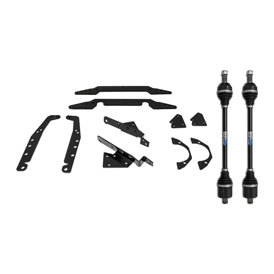
Item Description
A
Front Bracket (Aft)
B
Front Bracket (Fore)
C
Rear Shims
(Passenger Side)
T
Spacer, 35mm Lg.
U
Spacer, 30mm Lg.
Read instructions and view illustrations before beginning.
Need help with your installation?
sales@superatv.com
1-812-574-7777
Thank You
© 2013 SuperATV.com. All Rights Reserved.
B
V
Spacer, 25mm Lg.
W
Spacer, 31mm Lg.
www.superatv.com
8:00am - 9:00pm EST M-Th
8:00am - 7:00pm EST Friday
9:00am - 2:00pm EST Saturday
For Choosing
INSTALLATION INSTRUCTIONS
Polaris RZRXP 3"-5" Lift Kit
Qty
Item Description
1
T
35mm Lg. Spacer
1
U
30mm Lg. Spacers
2
V
25mm Lg. Spacers
W
31mm Lg. Spacers
A
(Kit contents continue on following page)
Liability Statement
SuperATV's products are designed to best fit users ATV/UTV under stock conditions.
Adding, modifying, or fabricating any factory, or aftermarket, parts will void any
warranty provided by SuperATV and is not recommended. SuperATV's products
could interfere with other aftermarket accessories. If user has aftermarket products
on machine, contact SuperATV to verify that they will work together.
Although SuperATV has thousands of satisfied customers, user should be aware
that installing lift kits, long travel, or suspension kits, tires, etc will change the ride
of machine and may increase maintenance and part wear. Operating any off-road
machine while, or after, consuming alcohol and/or drugs increases risk of bodily
harm or death. No warranty or representation is made as to this product's ability to
protect user from severe injury or death. SuperATV urges operators and occupants
to wear a helmet and appropriate riding gear at all times.
By purchasing and installing SuperATV products, user agrees that should damages
occur, SuperATV will not be held responsible for loss of time, use, labor fees,
replacement parts, or freight charges. SuperATV, nor any 3rd party, will not be held
responsible for any direct, indirect, incidental, special, or consequential damages
that result from any product purchased from SuperATV. The total liability of seller to
user for all damages, losses, and causes of action, if any, shall not exceed the total
purchase price paid for the product that gave rise to the claim.
SuperATV will warranty only parts provided by SuperATV. Any damage or problems
with OEM housings, bearings, seals, or other manufacturers products will not be
covered by SuperATV. SuperATV parts and products are not warrantied if item was
not installed properly, misused, or modified.
Qty
1
2
2
4
(Driver Side)
C
IN-LK-P-RZRXP-3-5 11/13/2013
Advertisement

Related Manuals for SuperATV LK-P-RZRXP-3-5


Summary of Contents for SuperATV LK-P-RZRXP-3-5
- Page 1 9:00am - 2:00pm EST Saturday By purchasing and installing SuperATV products, user agrees that should damages occur, SuperATV will not be held responsible for loss of time, use, labor fees, replacement parts, or freight charges. SuperATV, nor any 3rd party, will not be held...
- Page 2 (kit contents continued) (Passenger Side) (Driver Side) M8 x 25mm Lg. M8 x 30mm Lg. M8 x 55mm Lg. M8 Nylock Nut M10 Nylock Nut M10 x 65mm Lg. M12 Nylock Nut M12 x 55mm Lg. Item Description Right Rear Outer Bracket Right Rear Inner Bracket Right Rear Clamp Block Left Rear Outer Bracket...
- Page 3 Do not tighten hardware completely unless noted. Fig. 1 Keep all stock hardware for reuse. FRONT 1. Raise front of machine off ground, secure with jack stands. See Figs. 1 - 1a. Remove Wheels. Disconnect Wire Harness from Frame. Reinstall to a convenient location after Brackets have Frame been installed.
- Page 4 Steering Stop Installation (Rack and Pinion shown off machine for clarity) Fig. 1 10-7/8” Lg. Wire Tie 8” Lg. Wire Tie Bushings Bushing Fig. 1a Note: Driver Side installation is shown. 1. Unclamp and slide Boot away from Steering Gear Box. 2.
-
Page 5: Parts Reference
Front Brackets Installation, Fig. 2 Qty. (3) (Passenger Side) M10 Nylock Nut (Driver Side) Qty. (3) Front Frame M10 x 65mm Lg. (Driver Side) Front Lift Settings PARTS REFERENCE Item Description Front Bracket (Aft) Front Bracket (Fore) M10-1.50 x 65mm Lg. FHCS Highest M10-1.50 Nylock Nuts, Flange 35mm Lg. -
Page 6: Shock Mount
Rear Removal Keep all stock hardware for reuse. Fig. 3 1. Raise rear of machine off ground, secure with jack stands, remove Wheels, and Shocks (upper) from Shock Mount. See Fig. 3. Shock Mount 2. Unbolt Sway Bar. See Fig. 3c. Remove RSL’s from Spindles. - Page 7 Rear Shim Installation 1. Install Rear Shim (C) between Spindle and Trailing Arm with M12-1.75 x 55mm Lg. FHCS (R) and M12-1.75 Nylock Nuts, Flange (S). Bevel will face outside. Tighten hardware completely and repeat steps for opposite side. Driver Side shown in illustrations Qty.
- Page 8 Rear Brackets Installation Do not tighten hardware completely unless noted. 1. Install Rear Inner Bracket (H) to inside of Shock Mount and Frame. Secure to Frame with M8-1.25 x 30mm Lg. Self Tapping Bolt (P). Install Spacer (V) at this time. See Step 1. 2.
- Page 9 Rear Brackets Installation continued Driver Side shown this surface to outside of (Driver Side) factory Shock Mount Step 1: this surface to inside of Front factory Shock Mount Step 2: Lift Settings: Highest Lowest (Passenger Side) x Qty. (4) Frame Step 3: x Qty.
Need help?
Do you have a question about the LK-P-RZRXP-3-5 and is the answer not in the manual?
Questions and answers