Table of Contents
Advertisement
Form No. 1-1149
May 2016
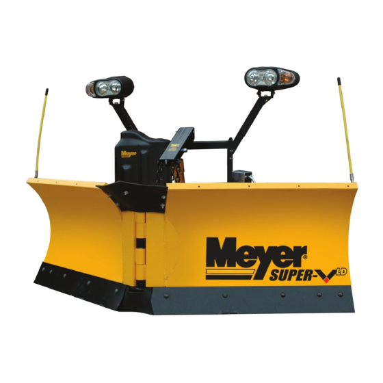
EZ Crate Assembly and Installation
51200 Super V LD Plow with V-71 12V Hydraulic Unit
Meyer Products LLC reserves the right, under its continuing product
improvement program, to change construction or design details,
Meyer Products LLC
specifications and prices without notice or without incurring any obligation.
18513 Euclid Ave. • Cleveland, Ohio 44112-1084
Phone 216-486-1313
© 2016 Printed in the U.S.A.
www.meyerproducts.com• email info@meyerproducts.com
Advertisement
Table of Contents

Related Manuals for Meyer 51200 Super V LD


Summary of Contents for Meyer 51200 Super V LD
- Page 1 Form No. 1-1149 May 2016 EZ Crate Assembly and Installation 51200 Super V LD Plow with V-71 12V Hydraulic Unit Meyer Products LLC reserves the right, under its continuing product improvement program, to change construction or design details, Meyer Products LLC specifications and prices without notice or without incurring any obligation.
-
Page 2: Table Of Contents
4. The vehicle must be equipped with a “Heavy Duty Battery” (70 Amp, Hr. Min.), 550 C.C.A. and “Alternator” (60 Amp. Min.) to obtain maximum performance. 5. Follow these instructions explicitly. Warranty does not apply to a Meyer product which has been negligently or improperly assembled or installed. -
Page 3: Illustrated Parts Lists
• Lift Frame Parts indented are included in the carton, bag or assembly under which they are indented. Meyer Products LLC reserves the right, under its continuing product improvement program, to change construction or design details, specifications and prices without notice or without incurring any obligation. - Page 4 Super V Plow Package Specific Components...
- Page 5 •• Bolt C 1/2-13 x 1-3/4” Parts indented are included in the assembly under which they are indented. Meyer Products LLC reserves the right, under its continuing product improvement program, to change construction or design details, specifications and prices without notice or without incurring any obligation.
-
Page 6: Build Assembly
Building Super V Plow 14. Attach lift arm (73) to lift frame (38) using 5/8-11 x 5-1/2” bolt (42) and 5/8-11 Position wing assemblies 75 & 76 face down on cardboard as not to locknut (43). damage the painted surfaces. Grease the bushings on both left and right wings. -
Page 7: Vehicle Side Wiring Diagram
(30) Attach Blue wire to a reverse signal on the vehicle. The blue wire is sensing when the vehicle is in reverse in order to operate HFP (Hands Top off the unit to the fill line on the reservoir with Meyer M-1 Hydraulic Fluid. 15059 Diode packed in Controller box NOTE: Proper fluid level is to the fill line on the reservoir for the V-71. -
Page 8: Drop Speed Adjustment
Check snow plow light blinkers to make sure the wires have not been reversed. Note: All electrical connections should have both ends coated with a dielectric grease, Meyer Part No. 15632, prior to final installation. This will ensure a good connection and help in preventing corrosion. -
Page 9: Mount Plow System To Vehicle
G. Remove weather cover on male end and connect one piece electrical plug. The spring loaded cover will lock one piece plug. Meyer Products assumes no responsibility for installations not made in accordance with these instructions. -
Page 10: Dis-Mount Plow System From Vehicle
C. Remove crankstand from lift frame. plug and install weather cover on male end. D. Attach crankstand to a-frame H. Back vehicle away from plow assembly. Meyer Products assumes no responsibility for installations not made in accordance with these instructions. -
Page 11: Pre-Delivery Inspection
PRE-DELIVERY INSPECTION Vehicle Make: Vehicle Model: Vehicle Year: Vehicle VIN#: Vehicle FGAWR: Installing Company: Mounting Type: Plow Type: EZ Plus Hydraulic Serial Number: Moldboard Serial Number: All bolts torqued to specification Plow Operation Up Clevis height Plow Operation Left & Right Suspension interference Clevis height in inches Plow Operation Vee, Scoop Left &... -
Page 12: Accessories
16529 Optional Light Guards Meyer 16536 (‘99-07 Ford) Winch Cradle 16537 (‘99 + Chevy) 16539 (‘99 + Dodge) Meyer Products LLC 18513 Euclid Ave. • Cleveland, Ohio 44112-1084 Phone 216-486-1313 www.meyerproducts.com• email info@meyerproducts.com © 2016 Printed in the U.S.A. (11)
Need help?
Do you have a question about the 51200 Super V LD and is the answer not in the manual?
Questions and answers