
Related Manuals for Olympus IPLEX RX Series


Summary of Contents for Olympus IPLEX RX Series
- Page 1 INSTRUCTIONS INDUSTRIAL VIDEOSCOPE IPLEX RX series IPLEX RT series IV9620RX IV9635RX IV9650RX IV9675RX IV9420RX IV9435RX IV9620RT IV9635RT IV9650RT IV9675RT IV9420RT IV9435RT...
- Page 2 Shinjuku Monolith, 3-1 Nishi-Shinjuku 2-chome, Shinjuku-ku, Tokyo 163-0914, Japan Telephone: +81 3 6901 4038 Wendenstrasse 14-18, 20097 Hamburg, Germany Telephone: (49)40-23-77-30 48 Woerd Avenue, Waltham, MA 02453, U.S.A. Telephone: +1 781 419 3900 L43, Office Tower, Langham Place, 8 Argyle Street, Mongkok, Kowloon, Hong Kong Telephone: +852 2481 7812 3 Acacia Place, Notting Hill VIC 3168, Australia Telephone: +61 130 013 2992...
-
Page 3: Table Of Contents
Contents Introduction .................... 1 Intended use ........................1 Instruction manual ......................1 Product configuration ......................1 Expanded functions of the IPLEX RX/RT series ............. 1 Important Information–Please Read Before Use ......... 1 Marks used in this manual ....................1 Safety precautions ......................2 General safety precautions .................. - Page 4 Recording images ....................32 Image recording preparation ................32 Recording a still image ..................33 Recording a movie image ................... 34 Appending a moving image (RX only) ............... 35 Replaying an image ....................36 Playing back on a full-screen view (retrieve screen) ........36 Multi-image view (thumbnail screen) ..............
- Page 5 Cleaning the main unit and control unit ............70 Storage precautions ..................... 70 Troubleshooting Troubleshooting guide ..................71 Error messages ....................71 Common problems ....................72 Requesting repair of this product ............... 74 Specifications Operating environment ..................75 Other specifications ..................... 75 External application standard ................
-
Page 7: Introduction
Before using the instrument, carefully read the contents of this manual to ensure that you use the instrument correctly. After reading the manual, store it and the warranty agreement in a safe place. If you have any questions about any information in this manual, please contact Olympus. Product configuration For information about the configuration of devices required by this product and devices that can be used in combination with it, see "System chart"... -
Page 8: Safety Precautions
Doing so may lead to low-temperature burns. Wear gloves or do something to prevent low- temperature burns. ● Use only a power cord and AC adapter specified by Olympus and connect the power cord to a 3P power outlet in rated range Otherwise, smoke, fire, or electric shock might occur. - Page 9 ● If an optical adapter cannot be mounted or removed because the nut will not turn, stop using it. Contact Olympus. ● Do not look directly into the illumination being emitted by the distal end.
- Page 10 ● Never connect any other USB device or USB cable to the USB connector except for the USB flash drive provided as standard or USB Flash Drive recommended by Olympus. ● Do not remove the battery or AC adapter while the system is running.
-
Page 11: Battery Precautions
Battery precautions Should you experience any problems when using the instrument with batteries, contact Olympus. Observe the precautions described below when handling the battery. Otherwise, battery fluid leak, excessive heat generation, smoke, battery burst, electric shock and/or burns may result. - Page 12 ● If you are having problems removing the battery from the instrument, do not apply undue force. Contact Olympus. ● Contact the airlines in advance when you transport the battery by the aircraft.
-
Page 13: Rating Plate/Caution Plate
Rating plate/caution plate The safety ratings, cautions, and serial number are on stickers on parts of the main unit and the control unit. If labels are missing or if their contents are illegible, contact Olympus. Main unit Model name, serial number... -
Page 14: Unpacking
Unpacking 1.1 Unpacking the instrument When unpacking the instrument, check to make sure that all of the items listed below are included. Should anything be missing or damaged, contact your original vendor or Olympus. Name Count Name Count Insertion tube fastening belt... -
Page 15: Nomenclature
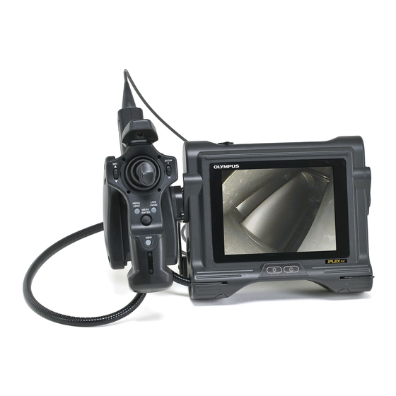
Nomenclature 2.1 Main unit/control unit nomenclature Main unit Name Name Handle Control unit LCD monitor Strap holder (covered by LCD protective sheet) Strap bracket Insertion tube (or scope) Front panel Angulation section Universal cable Distal end Optical adapter case holder Tip cap Ring Bend stopper... - Page 16 2 Nomenclature Control unit Name Name [ANGLE] joystick (Angulation operation) [FRZ/REC] button * (Freeze/record observed image [LIVE/GAIN] button (two locations; left and right)) (Live image display/gain (RX only)) [ZOOM] lever (Zooming the image) [MEAS/ENTER] joystick Hanger (Folder selection/Menu selection/ measurement operations (RX (Stereo (To hang the control unit on the main unit) measurement function) only)) Insertion tube holder...
-
Page 17: Distal End/Optical Adapter Nomenclature
2 Nomenclature 2.2 Distal end/optical adapter nomenclature 4-mm type 6-mm type ● Distal end ● Distal end ● Optical adapter ● Optical adapter Side view Forward view Side view Forward view ● Optical adapter internal view ● Optical adapter internal view ●... -
Page 18: Lcd Monitor Nomenclature
2 Nomenclature 2.3 LCD monitor nomenclature Live screen Name Battery indicator Freeze indicator Recording/playback indicator Gain mode (RX only) Brightness level Zoom level Date/Time Number of images that can be recorded USB flash drive indicator Title Thumbnail screen Sequence number Logo Light indicator Temperature indicator (RX only) -
Page 19: Pre-Observation/Pre-Operation Preparation And Inspection
Pre-observation/pre-operation preparation and inspection Be sure to finish the preparation and inspection work described in this chapter before using the instrument. At the first sign of any abnormality, immediately stop using the instrument and perform the required actions as described in "8 Troubleshooting" (P. 71). Inspections are not only required before use, but should be conducted periodically. - Page 20 3 Pre-observation/pre-operation preparation and inspection If you find it difficult to remove the battery, hook your finger directly onto the battery to remove it. Using the AC adapter AC adapter connector cap AC inlet Open the AC adapter connector cap. After connecting the provided AC power cord to the AC inlet of the AC adapter, plug the plug end of the AC power cord securely into a 3P power outlet.
-
Page 21: Pre-Operation Preparation
Also note that an optical adapter by itself is not watertight. ● If an optical adapter cannot be mounted or removed because the nut will not turn, stop using it. Contact Olympus. ● Never use the instrument while dirt or water is present in the optical adapter Water tightness between the optical adapter and the distal end may be lost, or the optical adapter or the distal end may be damaged. -
Page 22: Turning On Power
3 Pre-observation/pre-operation preparation and inspection Optical adapter Turn the optical adapter nut clockwise until the first screw thread passes over the con- necting screw thread. Optical adapter main body Once past the first screw thread, turn the entire main body of the optical adapter clock- wise while pushing gently until it fits into the positioning cut surface on the insertion tube’s distal end and can be turned no further. -
Page 23: Checking The Remaining Battery Level
3 Pre-observation/pre-operation preparation and inspection Checking the remaining battery level When operating the instrument under battery power, an indicator in the upper right corner of the screen shows remaining battery power. The table below shows general guidelines for remaining battery power. Indicator Battery condition Remaining battery power about 50% or more. -
Page 24: Checking Lighting Of Illumination At The Insertion Tube's Distal End
3 Pre-observation/pre-operation preparation and inspection Checking lighting of illumination at the insertion tube's distal end NOTE ● Always turn the LIGHT button ( ) on the front panel of the main unit OFF when the instrument is not in use, such as when replacing the optical adapter, etc. Turning ON the power will light the illumination automatically. -
Page 25: Attaching The Usb Flash Drive
3 Pre-observation/pre-operation preparation and inspection Attaching the USB flash drive Inserting the USB flash drive USB Flash Drive USB connector Slide the lock release lever to the side to open the battery cover. Noting the orientation of the USB flash drive, insert it terminals first. After inserting the USB flash drive, close the cover and slide the lock release lever back to the lock position. - Page 26 3 Pre-observation/pre-operation preparation and inspection ● Hang the main unit When hanging the main unit to do observation, hook an S-hook, string or other item onto the handle. ● Set up the main unit on a tripod Attach the tripod platform to the main unit to use a tripod to do observations. NOTE ●...
-
Page 27: Attaching The Shoulder Strap
3 Pre-observation/pre-operation preparation and inspection Attaching the shoulder strap The shoulder strap lets you attach the main unit to your body to do observations or to carry it around easily from your shoulder. Attach the main unit to your body Attach the shoulder strap hooks to the two belt brackets and one of the two belt holders. -
Page 28: Mounting Of The Control Unit On The Main Unit
3 Pre-observation/pre-operation preparation and inspection Mounting of the control unit on the main unit Handle Back attachment: For transport Side attachment: For observation Insert the hanger on the Hanger side of the control unit straight into the control unit holder on the side or the back of the main unit. - Page 29 3 Pre-observation/pre-operation preparation and inspection ● Walking with the control unit attached to the main unit (back, left side) Insert the slack of the universal cable between the handle and the main unit. Universal cable CAUTION ● When carrying the control unit fixed to the main unit, be careful for followings. - Hold the handle of the main unit - Take care not tot tilt or swing the main unit This instrument may be damaged.
-
Page 30: Securing The Insertion Tube To Move The Instrument To Another Location
3 Pre-observation/pre-operation preparation and inspection Securing the insertion tube to move the instrument to another location The insertion tube can be coiled with the insertion tube fastening belt when moving the instrument to another observation location. After coiling the insertion tube, wrap it with the insertion tube fastening belt near the insert tube bend stopper. -
Page 31: Pre-Operation/Post-Operation Inspections
AC adapter connector cap? Contact Olympus. Any irregularities such as damage to or deformation of the exterior material, buttons, joysticks, or levers? Irregularities such as cuts or kinks in the universal ca-... - Page 32 Any surface cracks or other abnormalities? Replacement required. NOTE Contact Olympus. ● The LCD monitor is manufactured based on precision technologies. The LCD monitor may contain pixels that do not light (visible as black dots) or light permanently (visible as bright dots). This does not indicate a defect or malfunc- tion of the product.
-
Page 33: Basic Operation
Basic operation 4.1 Viewing an observation object Turn on the illumination. While watching the display screen, insert the insertion tube into the observa- tion object. Insert carefully while checking the insertion direction. Use the [ANGLE] joystick to perform angulation operations and observe the ap- plicable locations on the display. - Page 34 4 Basic operation CAUTION ● Should the following message appears while inspecting with RX, immediately stop observation, carefully withdraw the insertion tube, and perform the required action as instructed in "Error messages" (P. 71). - HIGH TEMPERATURE (DISTAL END). PLEASE IMMEDIATELY PULL OUT THE INSERTION TUBE. ●...
-
Page 35: Adjusting The Image Display
4 Basic operation 4.2 Adjusting the image display Still image display (Freeze) While a live image is displayed, short-press the [FRZ/REC] button. This will freeze the observation screen image and display the freeze indicator ( ) in the upper right corner of the LCD monitor. Do not insert or withdraw the insertion tube while an image is frozen. -
Page 36: Adjusting Image Brightness
4 Basic operation Adjusting image brightness GAIN mode switching (RX only) Press the [LIVE/GAIN] button on the control unit while the live image is displayed. This switches the image's GAIN mode. When this operation is performed, the monitor screen shows the GAIN mode for about 3 seconds. -
Page 37: Switching The Folder From The Live Screen
4 Basic operation 4.3 Switching the folder from the live screen In the live screen, you can use the [MEAS/ENTER] joystick to switch the folder in which you are recording or playing back an image. While a live image is displayed, move the [MEAS/ENTER] joystick left, right, up, and down. -
Page 38: Recording Images
4 Basic operation 4.4 Recording images Still images and movie images can be recorded during observation. Data can be stored on the pro- vided USB flash drive for recording images. Use the provided USB flash drive or a recommended USB flash drive. Check to make sure that the USB flash drive is correctly loaded before using it. -
Page 39: Recording A Still Image
● You can use the FILE NAME MARK menu to specify addition of the letter "_A", "_B", "_C" or "_D" at the end of image file names. Use this function to categorize image files. ● The category names of the file marks can be changed.(Contact Olympus for details.) Recording a still image Select the folder of the save destination. -
Page 40: Recording A Movie Image
4 Basic operation Select the strings in the preset title list registered in advance, and short-press the [MEAS/ENTER] joystick. This records the still image. The screen shows "STILL" during recording a still image. The screen goes black for a moment and then the frozen image is displayed. -
Page 41: Appending A Moving Image (Rx Only)
4 Basic operation Select the mark to add to the end of the file name of the image you are record- ing, short-press the [MEAS/ENTER] joystick. Select the strings in the preset title list registered in advance, and short-press the [MEAS/ENTER] joystick. After a still image is recorded, the movie image recording confirmation window will appear. -
Page 42: Replaying An Image
4 Basic operation 4.5 Replaying an image Recorded images can be displayed using either of two screen views: a full-screen view of a single image (retrieve screen) or a multi-image view of thumbnail images (thumbnail screen). The thumbnail screen shows multiple images at a single glance, which makes it useful when find- ing a particular image among a large group of images. -
Page 43: Multi-Image View (Thumbnail Screen)
4 Basic operation NOTE ● The recorded still image can be measured in some cases. For details, refer to "6.7 Measurement" (P. 63). Multi-image view (thumbnail screen) The thumbnail screen shows multiple recorded movie and still images on a single screen (nine im- ages per screen). -
Page 44: Displaying A Pdf File (Rx Only)
4 Basic operation 4.6 Displaying a PDF file (RX only) You can display a PDF file on the Live or Freeze screen. Preparing a PDF file Create folder named "PDF" in the USB flash drive connected to your computer and copy PDF files you want to display into the folder. Connect the USB flash drive to the USB port of the main unit. -
Page 45: Displaying Live Images On An External Monitor
InHelp VIEWER can be used to make use of images recorded on this instrument. Recorded images are loaded directly on the PC from the USB flash drive containing those images. To use InHelp VIEWER software, download it from the Olympus website (http://www.olympus-ims. com/en/service-and-support/downloads/). -
Page 46: Menu Operations And Functions
Menu operations and functions 5.1 Performing menu operations Press the [MENU/EXIT] button. This displays the menu screen. Main menu Sub menu Tilt the [MEAS/ENTER] joystick up, down, left or right to select the menu item you want to execute. Press the [MEAS/ENTER] joystick to apply the setting and return to the previous screen. -
Page 47: Using The Live Screen/Freeze Screen
5 Menu operations and functions 5.2 Using the live screen/freeze screen Menu display and functions The settings described in the table below can be configured using the live screen/freeze screen menu. *: Initial default Main menu Sub menu Available settings TITLE INPUT Title input A title can be displayed in the live screen and in recorded im-... - Page 48 5 Menu operations and functions *: Initial default Main menu Sub menu Available settings RECORD PRINT Date, title, and other information recording SCREEN Specifies date, time, title, logo and other information included ON/OFF on the display and measurement results should be recorded in images.
- Page 49 LCD monitor. This setting can also be used to specify the type of information to be displayed. : Show the date, time, title, "OLYMPUS" logo, optical adapter name, zoom level, and brightness level. DATE/TIME/LOGO* : Show the date, time, title, and "OLYM- PUS"...
-
Page 50: Inputting A Title
5 Menu operations and functions *: Initial default Main menu Sub menu Available settings SETUP STEREO Sets the screen in monocular view or binocular view ADAPTER IM- Sets the display mode of the live image to either the monocu- AGE DISPLAY lar view type or the binocular view type. -
Page 51: Registering A Character String As A Preset Title
5 Menu operations and functions Selecting a preset title for input With this procedure, you select a preset character string and use it to input a title. For information about how to register frequently used text strings, see "Registering a character string as a preset title"... -
Page 52: Adjusting Image Sharpness (Rx Only)
5 Menu operations and functions NOTE ● The preset title list has five pages. To change pages, select the text string in line 1 or line 10 of the currently displayed page and then tilt the [MEAS/ENTER] joystick upwards or downwards. Select the line where you want to store the string and then press the [MEAS/ ENTER] joystick. -
Page 53: Setting The Date And Time
5 Menu operations and functions Setting the date and time Use the procedure below to configure date and time settings. SETUP > DATE TIME > Set DMY, H:M. Be sure to set the correct date and time before using the instrument for the first time. Date and time information is shown on the display and is also recorded on the print screen. -
Page 54: Using The Thumbnail/Retrieve Screens
5 Menu operations and functions 5.3 Using the thumbnail/retrieve screens Menu display and functions The menu displayed on the thumbnail/retrieve screen can be used for the following settings. Menu Available settings Image delete DELETE • CANCEL : Do not delete image. •... -
Page 55: Operations In The Pdf File Display Screen (Rx Only)
5 Menu operations and functions 5.4 Operations in the PDF file display screen (RX only) Menu items and functions On the menu on which the PDF file is displayed, you can work with that PDF file as shown below. *: Initial default PDF main Available settings menu... - Page 56 5 Menu operations and functions PDF main Available settings menu submenu DISPLAY PDF Allows you to display or hide the PDF file name, page num- INFORMA- ber of current page/total pages, position in page of portion TION being displayed (vertical/horizontal), and scroll bars on the PDF screen ON: Display OFF: Hide...
-
Page 57: Stereo Measurement Procedures (Rx (Stereo Measurement Function) Only)
As the measurement results obtained here are affected by surface conditions of the measurement object or image capturing conditions such as the brightness, Olympus cannot guarantee the ac- curacy of measurement results. We recommended that users identify the measurement accuracy through experiments. -
Page 58: Measurement Flow
6 Stereo measurement procedures (RX (stereo measurement function) only) 6.1 Measurement Flow The following shows measurement procedures and the screen flow. Attaching the stereo optical adapter (See P.53) Registering the new stereo optical adapter Selecting the registered or re-registering the stereo optical adapter stereo optical adapter (See P.54) (See P.57) -
Page 59: Attaching The Stereo Optical Adapter
6 Stereo measurement procedures (RX (stereo measurement function) only) 6.2 Attaching the stereo optical adapter See also "3.3 Pre-operation/post-operation inspections" (P. 25) for more information on attaching stereo optical adapters. Make sure that the O-ring in the distal end is properly attached. See "3.3 Pre-operation/post-operation inspections"... -
Page 60: Registering The New Stereo Optical Adapter Or Re-Registering The Stereo Optical Adapter
6 Stereo measurement procedures (RX (stereo measurement function) only) 6.3 Registering the new stereo optical adapter or re-reg- istering the stereo optical adapter To use a stereo optical adapter for stereo measurements, you need to register the stereo optical adapter to the main unit in advance. If the combination of the stereo optical adapter and the insertion tube is changed due to purchas- ing the additional optical adapter or repairing the insertion tube, etc., you need to register the new stereo optical adapter as well. - Page 61 6 Stereo measurement procedures (RX (stereo measurement function) only) Make sure that the adapter name and the serial number for the stereo optical adapter are correct and then select "OK" and press the [MEAS/ENTER] joystick. Make sure that the O-ring is attached to the distal end of the insertion tube and also the stereo optical adapter is securely attached.
-
Page 62: Re-Registering The Stereo Optical Adapter
6 Stereo measurement procedures (RX (stereo measurement function) only) NOTE ● Capturing a white image The white image affects measurement accuracy so it is necessary to adjust the brightness to the appropri- ate level as shown below. Optimum Excessive illumination Insufficient illumination Protrusion Bright enough that the... -
Page 63: Selecting The Registered Stereo Optical Adapter
6 Stereo measurement procedures (RX (stereo measurement function) only) 6.4 Selecting the registered stereo optical adapter If the stereo optical adapter has been registered, select the stereo optical adapter on the optical adapter selection screen. When the stereo optical adapter is attached to the insertion tube's distal end, select "SELECT OPTICAL ADAPTER"... -
Page 64: Checking Measurement Values
6 Stereo measurement procedures (RX (stereo measurement function) only) 6.5 Checking measurement values The measurement accuracy may be reduced by loose attachment of the optical adapter or dirt on the lens components. Confirm the measurement values after the stereo optical adapter is regis- tered, selected or before and after measurement. - Page 65 6 Stereo measurement procedures (RX (stereo measurement function) only) Write down the measurement results. When confirming the measurement values after the stereo optical adapter is reg- istered or selected, make sure that the measurement results are within ±5%. When confirming the measurement values before and after measurement, com- pare the measurement values before and after measurement and make sure that both measurement values are almost identical.
-
Page 66: Capturing Measurement Area
6 Stereo measurement procedures (RX (stereo measurement function) only) 6.6 Capturing measurement area Observe the measurement area and confirm that the image is appropriate for measurement. Use the spot ranging to confirm that the distance between the distal end of the optical adapter and the measurement area is appropriate. -
Page 67: Measuring The Distance To The Measurement Area By Spot Ranging
6 Stereo measurement procedures (RX (stereo measurement function) only) Measuring the distance to the measurement area by spot ranging The spot ranging calculates the distance between the distal end of the optical adapter and the measurement area on the live screen and the freeze screen. In case of the monocular view type, short-press the [MEAS/ENTER] joystick while displaying the live screen or the freeze screen or press the [ZOOM] lever toward [W] while displaying the live screen. - Page 68 6 Stereo measurement procedures (RX (stereo measurement function) only) Spot ranging screen Measure the object distance at the position of the cursor in the left image. The object distance indicator shows the distance between the distal end of the optical adapter and the measurement area by nine levels.
-
Page 69: Measurement
6 Stereo measurement procedures (RX (stereo measurement function) only) 6.7 Measurement Measurement While displaying the spot ranging screen, live/freeze screen (binocular view type) or the retrieve screen (image recorded in the binocular view type), short- press the [MEAS/ENTER] joystick. The measurement method selection screen is displayed. NOTE ●... -
Page 70: Measurement Screen
6 Stereo measurement procedures (RX (stereo measurement function) only) Measurement screen Explanation of the measurement screen Displaying the Instruction message box measurement Shows instructions, conditions, method etc. Cursor Corresponding point Specifies a mea- surement point or reference point. Right image area The three most recent mea- Point surement results are displayed. - Page 71 6 Stereo measurement procedures (RX (stereo measurement function) only) Menu display and functions Pressing the [MENU/EXIT] button in the measurement screen Menu Available settings CLEAR Clears the measurement point or reference point specified immediately before. ALL CLEAR Clears all specified measurement point or reference point. METHOD Selects a measurement method.
-
Page 72: Measurement Method Types
6 Stereo measurement procedures (RX (stereo measurement function) only) Measurement method types The measurement method selection screen is displayed immediately after starting stereo measure- ment, or if "METHOD" is selected in the measurement menu screen. The following four measurement methods are available. ... -
Page 73: Specification Of Measurement Points
6 Stereo measurement procedures (RX (stereo measurement function) only) AREA/LINES This mode allows for measuring the total length of multiple lines, each of which is specified by two measurement points. When the specification of the last measurement point causes the first-drawn line and last-drawn line to intersect, the area of the figure closed by the lines will be measured. -
Page 74: Storage And Maintenance
Though the battery life depends on the operating environment and frequency of use, replacement of the battery is recommended whenever the battery operation time becomes very short. Contact Olympus about changing the battery. For details about how to load and remove the battery, see "Using the battery" (P. 13). -
Page 75: Cleaning The Distal End
6 Storage and maintenance Cleaning the distal end Dirt or water droplets on the objective lens of the distal end Grasping the rigid portion of the distal end, use a clean, soft piece of gauze or a cotton swab to wipe off the dirt or water. -
Page 76: Cleaning The Lcd Monitor
6 Storage and maintenance Cleaning the LCD monitor LCD monitor viewing problems due to fingerprints and dirt Wipe the LCD monitor with a soft cloth dampened with clean water. Next, lightly wipe it with a clean, dry cloth. CAUTION ● Never use a chemically treated cloth or strong detergent, such as benzine or alcohol. Doing so may dam- age the surface of the LCD monitor. -
Page 77: Troubleshooting
Should even the slightest irregularity be suspected, do not use the instrument. Perform the actions described in "8.1 Troubleshooting guide" (P. 71). If the problem cannot be re- solved by the described remedial action, stop using the instrument and send it to Olympus for re- pair. -
Page 78: Common Problems
8 Troubleshooting Message Cause and recommended action The message prompts you to stop inspection because the self-check function was triggered. →Immediately pull the insertion tube out of the observation object. HIGH TEMPERATURE (DISTAL END). NOTE PLEASE IMMEDIATELY PULL OUT THE SCOPE. - Page 79 The USB flash drive being used for image recording is not the one provided and is All the functions stopped not one recommended by Olympus. →Remove the AC adapter or the battery from the main unit to turn off the power.
-
Page 80: Requesting Repair Of This Product
8 Troubleshooting 8.2 Requesting repair of this product Contact Olympus before requesting repair of this instrument. Include a detailed description of the malfunction and the conditions under which it occurs when returning the instrument. Malfunctions that occur during the warranty period are done at no charge according to the warranty agreement. -
Page 81: Specifications
Specifications 9.1 Operating environment Operating temperatures Insertion tube In air: -25 to 100 °C (RX) -25 to 80 °C (RT) In water: 10 to 30 °C Other parts than above In air: -10 to 40 °C (Battery-powered operation) 0 to 40 °C (AC adapter-powered operation) Operating atmospheric pressure Insertion tube In air:... - Page 82 : 50/60Hz For details, refer to the instruction manual of the battery charger. Power consumption MAX 15 W Recording media USB flash drive (For the recommended products, please contact Olympus.) Still image recording Resolution H768 x V576 (Pixels) Recording Files are stored as compressed JPEG format (Exif 2 compliant).
- Page 83 Weight Approximately 5.1 kg (with all items stowed: approximately 12 kg) Manufacturer OLYMPUS CORPORATION TOKYO, JAPAN NOTE ● The images recorded with the instrument can be displayed on a computer, etc., but playback on the instru- ment of images recorded with an image recording device such as a digital camera or a computer is not supported.
-
Page 84: External Application Standard
Refer to your local Olympus distributor for return and/or collection systems available in your country. Chinese RoHS Directive This mark indicates the environmental protection use period applicable to electronic infor- mation products sold in China in accordance with the "Management Methods for Control-... -
Page 85: Optical Adapter Specifications
9 Specifications 9.3 Optical adapter specifications For 4-mm type insertion tube When the optical adapter is mounted on the insertion tube. AT120D/NF AT120D/FF AT100S/NF AT100S/FF AT80D/FF Adapter name -IV94 -IV94 -IV94 -IV94 -IV94 Product abbreviation 120DN 120DF 100SN 100SF 80DF Character color Green Green... -
Page 86: Appendix
Appendix System chart Insertion tube fastening belt External monitor (commercially available) Optical adapter Shoulder strap case holder VGA conversion cable Carrying case RX/RT main unit 4-mm type (RX) 6-mm type (RX) • IV9420RX • IV9620RX • IV9435RX • IV9635RX • IV9650RX 4-mm type (RT) •... - Page 87 Appendix Optical adapter/Rigid sleeve Optical adapter (optional) 4-mm type • AT80D/FF-IV94 • AT120D/NF-IV94 • AT120D/FF-IV94 • AT120S/NF-IV94 • AT120S/FF-IV94 • AT50D/50D-IV94 • AT50S/50S-IV94 6-mm type • AT40D-IV96 • AT80D/NF-IV96 USB flash drive for • AT80D/FF-IV96 recording images • AT120D/NF-IV96 • AT120D/FF-IV96 •...
Need help?
Do you have a question about the IPLEX RX Series and is the answer not in the manual?
Questions and answers