Table of Contents
Advertisement
Quick Links
Advertisement
Table of Contents
Troubleshooting

Related Manuals for Olympus IPLEX FX Series


Summary of Contents for Olympus IPLEX FX Series
- Page 1 INSTRUCTIONS INDUSTRIAL VIDEOSCOPE IPLEX FX series...
-
Page 3: Table Of Contents
Signal words....................5 Dangers, warnings and cautions............. 5 Operating environment features.............. 9 Handling of the battery ................10 Product configurations of the IPLEX FX series ........12 Chapter 1 Checking the package contents ... 13 Checking the package contents ..........13 IPLEX FX series package contents............ - Page 4 Control unit nomenclature and functions ........ 19 Channel port nomenclature and functions (IV8635X1 only)...... 21 Optical adapter nomenclature and functions ......22 For 6-mm type................... 22 For 4-mm type................... 22 For 6.2-mm type (IV8635X1)..............23 LCD monitor nomenclature and functions ....... 25 Chapter 3 Preparation and inspection before observation ..........
- Page 5 Inspecting the optical adapter ........... 51 Inspecting the optical adapter optics and connecting screw threads ..51 Inspecting the parts of the optical adapter ..........52 Attaching and detaching the optical adapter ..........52 Inspecting the LCD monitor............55 Inspecting the external appearance ............55 Inspecting the LCD monitor holding section and LCD cable.....
- Page 6 Troubleshooting when the hook is caught (IV8635X1 only)...... 73 Adjusting the image ..............75 Still image (freeze) ..................75 Zoom ......................76 Adjusting the brightness................77 Recording the image ..............79 Image recording preparation ..............79 Recording a still image................82 Recording audio with still images..............
- Page 7 Delete image ................... 119 Move images/copy images..............121 Searching images ................... 122 Add/rename/delete folder................ 124 Format recording card/internal memory/USB memory......127 Chapter 6 Measurement procedures....128 Measuring from three dimensional (3D) coordinates (stereo measurement) .............. 129 Measurement accuracy................129 Flow of stereo measurement..............130 Attaching the stereo optical adapter............
- Page 8 Cleaning..................163 Repacking the case ..............164 Secure the case with the belt ..............166 Cleaning/storing the hook assembly (IV8635X1 only) ..167 Cleaning the hook assembly ..............167 Storing the hook assembly..............167 Storage precautions ..............169 Chapter 9 Troubleshooting ........
-
Page 9: Warning And Rating Plates
Warning and Rating Plates Safety-related labels and symbols are attached to the instrument at the locations shown below. If labels or symbols are missing or illegible, please contact Olympus. 6. CARD warning mark 3. LCD monitor warning plate 4. Rating plate C 2. -
Page 10: Rating Plate B
2. Rating plate B 3. LCD monitor warning plate... -
Page 11: Rating Plate C
4. Rating plate C 5. Scope unit warning plate 6. CARD warning mark 7. Battery warning plate 8. Cover warning mark... -
Page 12: Important Information - Please Read Before Use
Important Information – Please Read Before Use Intended use This instrument has been designed to be used with IPLEX FX series and ancillary equipment for observation and examination of the insides of a machinery, equipment or building that cannot be observed directly from the outside. -
Page 13: Signal Words
Signal words The following signal words are used throughout this manual. DANGER • Indicates an imminently hazardous situation which, if not avoided, will result in death or serious injury. WARNING • Indicates a potentially hazardous situation which, if not avoided, could result in death or serious injury. - Page 14 RECORDING CARD slot. Should any foreign object enter the instrument, remove the battery and the AC adapter from the base unit and immediately contact Olympus. • Do not touch the connectors directly by hand. Otherwise, a malfunction or electric shock may result.
- Page 15 • Use USB connectors only to connect via a USB cable to a computer, a USB memory, or a USB keyboard recommended by Olympus. Never connect any other type of USB device. • Make sure that battery cover, I/F connector cover, slot cover, AC adapter cover are firmly closed.
- Page 16 TIFF-YC format. Use bundled IPLEX VIEWER PLUS to play back TIFF images from the IPLEX FX series on your computer. • Windows Media Player is either registered trademarks or trademarks of Microsoft Inc. in the U.S.
-
Page 17: Operating Environment Features
Operating environment features The operating environment performance is confirmed by the following tests (United States Defense Standard) under battery operation. Note, however, that meeting operating environment specifications does not constitute any guarantee against damage to or malfunction of this equipment. Also, subjecting this equipment to strong shock or impact may cause the equipment to no longer meet operating environment specifications. -
Page 18: Handling Of The Battery
• Do not use a battery that is not recommended for IPLEX FX series. • Do not attempt to recharge a battery that is not designated for IPLEX FX series. • If the battery charger cannot complete battery charging in the specified recharging time, stop trying to recharge the battery. - Page 19 • The battery is hot after long hours of operation of IPLEX FX series. Do not take out the battery immediately after use, as this may result in burning your hand.
-
Page 20: Product Configurations Of The Iplex Fx Series
Product configurations of the IPLEX FX series The IPLEX FX series includes base unit IV8000-2 with a scope unit selected from the following available model. The simplified specifications of the scope units are shown below. For detailed specifications of the individual models, see “Chapter 10 Specifications”... -
Page 21: Chapter 1 Checking The Package Contents
Chapter 1 Checking the package contents Checking the package contents Match all items in the package with the components shown on “IPLEX FX series package contents” below. If any item is damaged, a component is missing or you have any questions, do not use the instrument, but immediately contact Olympus. - Page 22 Chapter 1 Checking the package contents Name Count Instruction Manual IPLEX FX series (This booklet) IPLEX FX Quick guide AC adapter USB/card reader/writer IPLEX FX utility disc Software license agreement Spare tag for CF card Scope unit name sticker *3...
-
Page 23: Chapter 2 Instrument Nomenclature And Functions
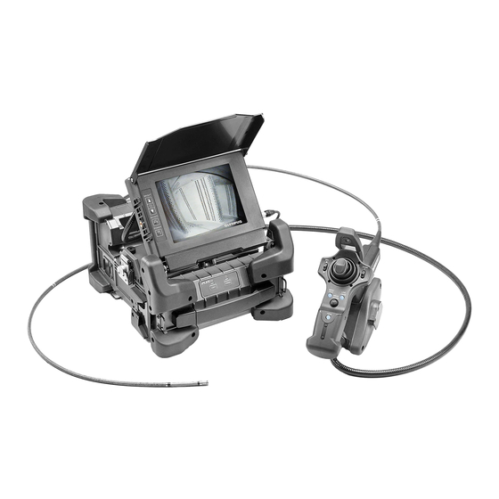
Chapter 2 Instrument nomenclature and functions System nomenclature Base unit Strap holder Front panel Scope handset holder LCD monitor Angulation section Strap holder Universal cable Insertion tube Bend stopper Tip cap Scope unit Control unit... - Page 24 Chapter 2 Instrument nomenclature and functions Handle Optical adapter case holder Shoulder strap...
-
Page 25: Base Unit Nomenclature And Functions
Chapter 2 Instrument nomenclature and functions Base unit nomenclature and functions Slot cover RECORDING CARD slot (Insert a recording card for image recording.) USB connector Mic connector Aux connector (for extension) Video connector I/F connector cover AC adapter S-video connector cover AC adapter Battery cover... - Page 26 Chapter 2 Instrument nomenclature and functions [LIGHT] [POWER] indicator indicator [POWER] button [LIGHT] button...
-
Page 27: Control Unit Nomenclature And Functions
Chapter 2 Instrument nomenclature and functions Control unit nomenclature and functions [ANGLE] Joystick Angulation operation [LIVE/GAIN] button Live image display/gain [MEAS/ENTER] joystick Menu selection/ measurement [VIEW] button Retrieve screen display/thumbnail [BRT] lever screen display Adjusting the brightness [MENU/EXIT] button Menu display Grip [FRZ/REC] button Freeze/record observed image... - Page 28 Chapter 2 Instrument nomenclature and functions Insertion tube holder Stopper To prevent accidental operation of the angulation lock [ANGLE LOCK] lever To lock the angulation operation Strap NOTE • The insertion tube can temporarily be fixed on the control unit by inserting it into the insertion tube holder hole.
-
Page 29: Channel Port Nomenclature And Functions (Iv8635X1 Only)
Chapter 2 Instrument nomenclature and functions Channel port nomenclature and functions (IV8635X1 only) Safety cap Port cap Strap Handle holder Chuck screw To lock or unlock the provided Channel port hook assembly. -
Page 30: Optical Adapter Nomenclature And Functions
Chapter 2 Instrument nomenclature and functions Optical adapter nomenclature and functions For 6-mm type Objective lens Objective lens O-ring Illumination Connecting screw Product abbreviation See “Optical adapter specifications” (page 193) Objective lens Electrode Optical adapter positioning groove Illumination Product abbreviation See “Optical adapter specifications”... -
Page 31: For 6.2-Mm Type (Iv8635X1)
Chapter 2 Instrument nomenclature and functions For 6.2-mm type (IV8635X1) Objective lens Objective lens O-ring Connecting screw Illumination Product abbreviation See “Optical adapter specifications” (page 194) Objective lens Electrode Optical adapter Illumination positioning groove Channel Product abbreviation See “Optical adapter specifications” (page 194) (Optical adapter internal view) Positioning pin Electrode... - Page 32 Chapter 2 Instrument nomenclature and functions Storage in the optical adapter case The optical adapter, the O-ring (for 6-mm or 6.2 mm type) and optical data media (CF card or USB memory) need to be stored in the optical adapter case provided with the scope unit.
-
Page 33: Lcd Monitor Nomenclature And Functions
Chapter 2 Instrument nomenclature and functions LCD monitor nomenclature and functions Shade [BRIGHTNESS] buttons Press either button to adjust the brightness of the LCD monitor back light. [ROTATE] button [TITLE] button Rotates the LCD Starts up the title monitor image by input window. -
Page 34: Chapter 3 Preparation And Inspection Before Observation
“Chapter 9 Troubleshooting” (page 170) to solve the problem. If irregularity is still suspected, contact Olympus. Damage or irregularity may compromise the correct functioning of the instrument and may result in more severe damage to the examined subject. -
Page 35: Towing Using The Extendable Handle
Chapter 3 Preparation and inspection before observation Towing using the extendable handle Make sure that the latch is completely closed. CAUTION • If the latch is not completely closed, the top cover may open accidentally when the case is lifted. Pull the lock lever towards you to unlock and extend the handle. - Page 36 Chapter 3 Preparation and inspection before observation CAUTION • Always bring the wheels in contact with the ground before rolling the case. Otherwise, the case may be damaged or fall over. • Move the case carefully when going over a step. Be careful that the case does not fall over. •...
-
Page 37: Taking The Instrument Out Of The Case
Chapter 3 Preparation and inspection before observation Taking the instrument out of the case Remove the equipment in the order of: Insertion tube → Control unit → Base unit. Storage bag Control unit Insertion tube Storage bag Take the insertion tube, which is Base unit on the drum, out of its storage bag. - Page 38 Chapter 3 Preparation and inspection before observation • When removing the insertion tube from the drum, do not apply excessive force. Otherwise, the insertion tube may be damaged. • When taking the control unit or base unit out of the case, never hold them by the scope (including the bend stopper), universal cable, LCD cable or LCD monitor.
-
Page 39: Laying Down The Base Unit
Chapter 3 Preparation and inspection before observation Laying down the base unit The base unit can be operated either on its side or on its base as illustrated below. Operated on its base Operated on its side CAUTION • Place the base unit on a level surface so it is stable. The base unit can tip over if it is not stable. -
Page 40: Replacing The Scope Unit
Chapter 3 Preparation and inspection before observation Replacing the scope unit The scope unit must be changed to switch the scope’s insertion unit from the 4-mm type to the 6-mm type. WARNING • When replacing the scope unit, choose a location where foreign matter, dust, rain will not get on it. -
Page 41: Attaching The Scope Unit
Chapter 3 Preparation and inspection before observation Remove the scope unit. Latches Attaching the scope unit CAUTION • Always attach the scope unit on a flat surface. • Take care that static electricity does not short between the base unit’s CCU connector and the scope unit. - Page 42 Chapter 3 Preparation and inspection before observation Line up the marks on the scope unit and the base unit while positioning the scope unit on the base unit and then rotate the latches (two positions) clockwise to lock them. Marks Latches Slit CCU connector...
- Page 43 Chapter 3 Preparation and inspection before observation The universal cable can be inserted into the notch.
-
Page 44: Preparing The Power Supply
Chapter 3 Preparation and inspection before observation Preparing the power supply WARNING • Do not bend, pull, twist, crush or apply excessive force to the power cord of the AC adapter. Otherwise, a break in the power cord wires may cause a fire or electric shock. •... - Page 45 Chapter 3 Preparation and inspection before observation Align a fully charged battery with the notch in the opening and insert the battery. Insert the battery until you hear a click and make sure that the hooks on the mouth of the case are engaged. Hook Close the battery cover and turn the battery cover screws clockwise.
-
Page 46: Supplying Power From The Ac Adapter
Chapter 3 Preparation and inspection before observation Supplying power from the AC adapter Connect the AC adapter to the AC adapter connector on the base unit. Ensure that the AC power cord is connected securely to the AC inlet of the AC power adapter. Plug the AC power cord securely into a power outlet. -
Page 47: Inspecting The Scope
Chapter 3 Preparation and inspection before observation Inspecting the scope CAUTION • Be sure to hold the scope by a position on the rear of the angulation section. Otherwise, the angulation section may be damaged. Inspecting the external appearance of the scope Check visually that the external finish of the complete length of the scope and universal cable are free of irregularities such as deformation. -
Page 48: Inspecting The O-Ring
Chapter 3 Preparation and inspection before observation Check that there is no dirt or water on the objective lens and the electrodes of the scope distal end. If dust or water is present, wipe them clean with a soft piece of gauze, a cotton swab, or a sweep them off with a brush, grasping at hard part of distal end. - Page 49 O-ring. You should periodically replace the O-ring. 4-mm type The O-ring on the 4-mm type is in the optical adapter. O-ring CAUTION • Since user inspection of the 4 mm type is difficult you should have it inspected periodically by Olympus.
-
Page 50: Inspecting The Control Unit And The Universal Cable
Chapter 3 Preparation and inspection before observation 6.2-mm type (with channel) The O-ring on the 6.2-mm type is on the distal end of the scope. On the 6.2-mm type, if the o-ring is not present then the area is colored yellow and will therefore be visible. -
Page 51: Inspecting The Channel Port (Iv8635X1 Only)
Chapter 3 Preparation and inspection before observation Inspecting the channel port (IV8635X1 only) Check that the chuck screw is not abnormally deformed, has no foreign object attached to it, and can be rotated smoothly. Check that the projections and planes are not deformed and have no foreign objects attached. - Page 52 Chapter 3 Preparation and inspection before observation Make sure that the hook assembly can be clamped and released by tightening or loosening the chuck screw of the hook assembly. Chuck screw...
-
Page 53: Inspecting/Replacing The Safety Cap (Iv8635X1 Only)
Chapter 3 Preparation and inspection before observation Inspecting/replacing the safety cap (IV8635X1 only) Inspecting the safety cap CAUTION • If the safety cap cannot be attached securely to the end without the hook of the provided hook assembly or if there is any other irregularities such as break of the strap, replace the safety cap with the spare. - Page 54 Chapter 3 Preparation and inspection before observation Replacing the safety cap Holding the strap, firmly pull the safety cap from the universal cable and separate the fixing ring. Open the fixing ring on the new safety cap, and attach to the universal cable in the position shown in the following diagram.
-
Page 55: Preparation Of The Hook Assembly (Iv8635X1 Only)
Chapter 3 Preparation and inspection before observation Preparation of the hook assembly (IV8635X1 only) Inspecting the hook assembly WARNING • Be extra careful when handling the hook assembly to avoid connecting your eye with the tip. CAUTION • Be sure to inspect the hook assembly every time it is used. If you suspect an anomaly, use a spare. - Page 56 Chapter 3 Preparation and inspection before observation Make sure that the hook assembly is composed of the spring shaft and the hook attached to it. Hook Spring shaft Slits Distal end Hook assembly Proximal end CAUTION • If the hook becomes trapped or caught in the inspection object, the hook will break at the slit portion in order to allow scope withdrawal.
-
Page 57: Attaching The Hook To The Spring Shaft
Chapter 3 Preparation and inspection before observation Attaching the hook to the spring shaft WARNING • Be careful in handling the hook assembly so as not to avoid contact with your eye. CAUTION • Do not use the hook once detached from the spring shaft. The hook is replaceable. - Page 58 Chapter 3 Preparation and inspection before observation While pressing the hook straight against the spring shaft, slowly turn the hook clockwise to screw it onto the spring shaft. The gap between the hook and butting position is 0 to 0.2 mm. Slits 0 to 0.2 mm Spring shaft distal end...
-
Page 59: Inspecting The Optical Adapter
Chapter 3 Preparation and inspection before observation Inspecting the optical adapter Inspecting the optical adapter optics and connecting screw threads Check that there is no dirt or water on the inner and outer of the objective lens and the electrodes. If dust or water is present, wipe them clean with a soft piece of gauze, a cotton swab, or a sweep them off with a brush. -
Page 60: Inspecting The Parts Of The Optical Adapter
Chapter 3 Preparation and inspection before observation CAUTION • Note that insufficient cleaning can result in a loss of waterproofing between the optical adapter and the scope’s distal end. • Cleaning should be done periodically in order to maintain water resistance. Inspecting the parts of the optical adapter Check that the parts of the optical adapter are not loose. - Page 61 Chapter 3 Preparation and inspection before observation 4-mm type Optical adapter positioning cut surface Second screw thread Optical adapter Distal end of scope O-ring Connecting screw thread First screw thread 6.2-mm type (for IV8635X1) Second screw thread Optical adapter positioning groove Connecting screw thread Optical adapter Distal end of scope...
- Page 62 CAUTION • If you cannot mount or remove the optical adapter because the nut will not turn, stop using it and contact Olympus. • The optical adapter is a precise instrument using glass components in the optical system. Do not drop it or hit it against hard surfaces.
-
Page 63: Inspecting The Lcd Monitor
Chapter 3 Preparation and inspection before observation Inspecting the LCD monitor Inspecting the external appearance Check that the LCD monitor is free of irregularities such as cracks on the screen and holding section deformations. Check that the LCD monitor can be tilted smoothly. NOTE •... - Page 64 Chapter 3 Preparation and inspection before observation CAUTION • Do not touch the connector with wet hands. NOTE • The LCD monitor can be removed from the base unit and used by using the optional LCD extension cable. To remove it, first remove the LCD cable from the LCD monitor and then loosen the LCD monitor holding screws.
-
Page 65: Attaching And Detaching The Strap
When you want to hang the base unit from your shoulder, attach the shoulder strap. Be careful not to use a shoulder strap other than those designated by Olympus. WARNING • Never attempt to carry an object other than the base unit using the shoulder strap. Otherwise, the strap may be damaged and cause the base unit to drop. -
Page 66: Removing The Strap
Chapter 3 Preparation and inspection before observation Adjust the length of the shoulder strap using its length adjuster. Adjuster Use the shoulder strap to hang the base unit from your shoulder. Removing the strap To remove the strap; while pushing the hook lever of the shoulder strap with your finger, remove the strap from the strap ring of the base unit. -
Page 67: Installation Of The Control Unit On The Base Unit
Chapter 3 Preparation and inspection before observation 3.10 Installation of the control unit on the base unit The control unit can be attached to the base unit as desired. It can be attached to the base unit for carrying and left attached to the base unit during observation. Fit the hanger on the side of the control unit into the scope handset holder on the side of the base unit. - Page 68 Chapter 3 Preparation and inspection before observation CAUTION • Take care not to tilt or swing the base unit when carrying it with the control unit attached. Doing so may cause the control unit to detach and drop from the main unit. •...
-
Page 69: Chapter 4 Basic Operations
Chapter 4 Basic operations Turning on the power Turning the power on Press and hold the [POWER] button on the base unit for 2 seconds, the POWER indicator lights so you can check if the power is on. [POWER] indicator [POWER] button NOTE •... -
Page 70: Checking The Lcd Monitor Image
Chapter 4 Basic operations Checking the LCD monitor image Open the shade of the LCD monitor and ensure that the LCD monitor displays the observation image. Make sure there are no dark patches or dirt in the image. If you find any irregularities, go back to “3.5 Inspecting the scope”... -
Page 71: Display Language Setting
Chapter 4 Basic operations Display language setting Select the language to be used for menus and other display text before using the system for the first time. For more information, see “Language selection” (page 113). Date and time settings Set the current date and time before using the system for the first time. For more information, see “Setting the date and time”... -
Page 72: White Balance Adjustment
Manipulate the [ANGLE] joystick slowly and ensure that the angulation section moves smoothly. CAUTION • Repair is required if the joystick shaft is bent or if the knob comes off. Contact Olympus. NOTE • The angulation movement is interlocked with the angle and direction of the [ANGLE] joystick... -
Page 73: Checking The Angulation Lock
Chapter 4 Basic operations Checking the angulation lock Remove the stopper. Stopper While the [ANGLE LOCK] lever is pulled out and locked, confirm that angulation remains locked even when you remove your finger from the [ANGLE] joystick. Confirm that the [ANGLE LOCK] lever unlocks when you press it down again. -
Page 74: Attaching The Hook Assembly (Iv8635X1 Only)
CAUTION • Before inspection, read the appropriate inspection manual. • Do not insert anything into the channel other than the tools recommended by OLYMPUS. Loosen the chuck screw on the channel port so that the hook assembly can be passed through it. - Page 75 Chapter 4 Basic operations CAUTION • Do not adjust the angle when the hook assembly is protruding 150 mm or more from the tip of the scope. There is a risk of damage to the scope. Attach the safety cap to the proximal end of the hook assembly. WARNING •...
-
Page 76: Inserting The Scope
Chapter 4 Basic operations Inserting the scope Holding the control unit and scope In general, the [ANGLE] joystick of the control unit is manipulated with the thumb of the hand holding the grip of the control unit. Other buttons are also to be manipulated with the fingers of the hand holding the grip of the control unit. -
Page 77: Inserting The Scope
• Read and understand the contents of “Important Information – Please Read Before Use” (page 4) before using the scope. In case of any questions, contact Olympus. - Page 78 Chapter 4 Basic operations CAUTION • The message shown below may display when the illumination goes off and the observed image becomes dark during an inspection. This indicates that there is problem with the electrodes caused by foreign matter in between the optical adapter and the scope distal end. In this case, immediately stop operation, gently remove the scope and follow the instructions on page 171 under “Error messages”.
-
Page 79: Angulation Operation
Chapter 4 Basic operations • Whenever the red temperature indicator and a temperature warning message appears along with an audible warning alarm, immediately withdraw the scope from the object of observation. Continued use risks damage to the insertion tube and the optical adapter, resulting in malfunction and reduced illumination. -
Page 80: Withdrawing The Scope
Chapter 4 Basic operations Withdrawing the scope WARNING • The distal end of the scope becomes hot just after use in high-temperature atmospheres. Do not touch it directly to avoid burns. CAUTION • Do not withdraw the scope while its angulation is locked or while your finger is placed on the [ANGLE] joystick. -
Page 81: Withdrawing The Scope
Chapter 4 Basic operations Withdrawing the scope Remove your finger from the [ANGLE] joystick and carefully observe as you withdraw the scope. Troubleshooting when the hook is caught (IV8635X1 only) Protrude the hook assembly from the scope’s distal end and turn the hook assembly to unhitch the hook. - Page 82 Chapter 4 Basic operations CAUTION • When jettisoning the hook the scope may be damaged, accordingly jettisoning the hook should only be done as a last resort to dislodge a hook that is caught. Any damage caused by jettisoning the hook is not covered under warranty and repairs are the responsibility of the owner.
-
Page 83: Adjusting The Image
Chapter 4 Basic operations Adjusting the image Still image (freeze) CAUTION • Do not insert and withdraw the scope when the image is frozen. Press the [FRZ/REC] button on the side of the control unit to freeze the observed image. The LCD monitor displays the freeze indicator ) on the top right of the screen. -
Page 84: Zoom
Chapter 4 Basic operations Zoom When the live image is displayed, tilt the [ZOOM] lever on the control unit toward [T] to zoom (magnify) the observation image. The zoom level will be displayed for about 3 seconds on the monitor screen. While the zoomed image is displayed, the LCD monitor displays “ZOOM”... -
Page 85: Adjusting The Brightness
Chapter 4 Basic operations Adjusting the brightness The brightness can be controlled either by “GAIN mode switching”, “Automatic brightness control” or “Contrast correction”. GAIN mode switching Press the [LIVE/GAIN] button on the control unit while the live image is displayed. This switches the image’s GAIN mode. When this operation is performed, the monitor screen shows the GAIN mode for about 3 seconds. - Page 86 Chapter 4 Basic operations Contrast correction with the [BRT] lever During display of a frozen or retrieved image, operating the [BRT] lever on the control unit allows the contrast to be corrected in five steps. When the contrast correction level is “0”, an image without contrast correction is displayed.
-
Page 87: Recording The Image
Chapter 4 Basic operations Recording the image Image recording preparation The recording card or USB memory should always be formatted on the base unit. See “Format recording card/internal memory/USB memory” (page 127) for the operating procedure. CAUTION • If the recording card or USB memory is removed during image or audio recording, the data in the recording media may be destroyed. - Page 88 Chapter 4 Basic operations Insert a recording card Insert a recording card (CF card) specified by OLYMPUS into the RECORDING CARD slot on the base unit. EJECT button Recording card RECORDING CARD slot CAUTION • Be sure to insert the recording card into the recording card slot in the orientation shown in the figure above.
- Page 89 Chapter 4 Basic operations NOTE • When “ON” is selected in the “PRINT SCREEN” menu to record still images and a stereo optical adapter is attached, two still images are recorded: one with the displayed date/time, title, logo display, and measurement results and one without. Also, when recording a moving image, the moving image and a still image are recorded with the date/time, title, logo display as well as a still image without.
-
Page 90: Recording A Still Image
USB memory recommended by Olympus. Contact Olympus for information about USB memories. • Contact Olympus for details on setting the recording destination for still images to “PC” or “MAIL ONLY”. Press the [FRZ/REC] button (briefly) on the control unit to freeze the image. -
Page 91: Recording Audio With Still Images
Chapter 4 Basic operations Recording audio with still images Connect the microphone to the microphone connector. Use a microphone that is recommended by Olympus. Contact Olympus for information about microphones. MICROPHONE In the “RECORD” menu, set STILL AUDIO to “ON” (see page 95). - Page 92 • If you select “NO” in the still audio recording confirmation window, the still image will be recorded without the audio. • You can record audio with still images to the recording card provided as standard, to the internal memory, or to a USB memory recommended by Olympus. Contact Olympus for information about USB memories.
-
Page 93: Recording A Moving Image
NOTE • You can record moving images to the recording card provided as standard, to the internal memory, or to a USB memory recommended by Olympus. Contact Olympus for information about USB memories. • You can record high-definition moving images by selecting “HIGH: VGA” on the “MOVIE QUAL”... - Page 94 Chapter 4 Basic operations Select “YES AUDIO ON” for recording audio with the movie or select “YES AUDIO OFF” for recording the movie without audio, and press the [MEAS/ENTER] joystick. Moving image recording starts. The screen shows “MOVIE” and a flashing red dot during recording of a moving image.
- Page 95 Chapter 4 Basic operations Appending a moving image You can append newly a moving image to the last moving image. Press the [FRZ/REC] button for at least two seconds (long push) while a live image is displayed. When the moving image confirmation window shown below is displayed, select “CONTINUE”...
-
Page 96: Replaying The Image
Chapter 4 Basic operations Replaying the image Quick replay of most recent image Press the [VIEW] button in the live screen to display the most recently recorded image in full screen (the retrieve screen). Displaying the thumbnail screen and selecting the image to be replayed The example describes displaying images recorded on a recording card. - Page 97 Chapter 4 Basic operations Move the thumbnail selection frame with the [MEAS/ENTER] joystick to select the desired thumbnail image. If more than nine movies are recorded in one folder and the thumbnail selection frame is on the top (bottom) thumbnail which is the first (last) image in the folder, tilting the [MEAS/ENTER] joystick up (down) moves the thumbnail selection frame to the last (first) image in the folder.
-
Page 98: Stopping Playback Of Still Images With Audio
Chapter 4 Basic operations Image playback (retrieve) After selecting the desired image with the thumbnail selection frame, push the [MEAS/ENTER] joystick to retrieve the selected image. (Retrieve image) When the selected image is a moving image, the thumbnail screen is displayed automatically after the movie is finished playing. -
Page 99: Slide Retrieval
Chapter 4 Basic operations • Pressing the [MEAS/ENTER] joystick while paused, starts the moving image from the point where the position indicator is. • Pressing the [FRZ/REC] button while paused, records the paused image as a still image. • When the [LIVE/GAIN] button is pressed while playing moving images, the playing stops and the live screen appears. -
Page 100: Chapter 5 Menu Operations And Functions
Chapter 5 Menu operations and functions The [MENU/EXIT] button on the control unit makes it possible to display a menu and perform settings and control of various functions. Operating menu Menu operations Press the [MENU/EXIT] button to display the main menu. Tilt the [MEAS/ENTER] joystick up, down, left or right to select the menu to open. - Page 101 Chapter 5 Menu operations and functions Tilt the [MEAS/ENTER] joystick up or down to select “SET UP”, then push the [MEAS/ENTER] joystick. Now the SET UP menu appears. Tilt the [MEAS/ENTER] joystick to select “AUDIO VOL”. Tilt the [MEAS/ENTER] joystick left or right to select “OFF”, “LOW”, “MEDIUM”...
-
Page 102: Using The Live Screen/Frozen Screen
Chapter 5 Menu operations and functions Using the live screen/frozen screen Live screen/frozen screen menu display and functions The menu on the live screen/frozen screen can be used for the following settings. Main menu Submenu Description of function Initial status TITLE —... - Page 103 Sets the display at the bottom line on the D/T/LOGO screen. Displays date, time and title. : Displays date, time, title, note, OLYMPUS logo, optical adapter name, zoom level, and brightness level. D/T/LOGO: Displays date, time, title, and OLYMPUS logo.
- Page 104 <When “USB” is set as “PC”> CF: Images are recorded to recording card. C:\: Images are recorded to internal memory. PC: Images are recorded to computer. Contact Olympus for details on setting “PC” or “MAIL ONLY”. Sets the operations for the [FRZ/REC] button. STILL/...
- Page 105 MEM/KYBD : USB memory and keyboards can be used. : Use while connected to a computer. Restart the base unit after this setting. Contact Olympus for details about using the [PC] setting. SET UP COLOR Sets the color of the display other than the...
- Page 106 Chapter 5 Menu operations and functions Main menu Submenu Description of function Initial status SET UP LANGUAGE Switches the menu display language. ENGLISH Select from English, French, Spanish, Japanese, Korean or Chinese for NTSC. Select from English, French, German, Italian, Spanish, Russian or Chinese for PAL.
-
Page 107: Inputting The Title
Chapter 5 Menu operations and functions Inputting the title A title can be displayed in the live screen/frozen screen. The displayed title can be recorded together with the image. The recorded title of the image can also be modified. NOTE •... - Page 108 Chapter 5 Menu operations and functions Title input operations There are three ways to input titles, as follows. • Input text from the on-screen keyboard • Access favorites to input • Input from a USB keyboard Input text from the on-screen keyboard Select an input mode.
- Page 109 Input from a USB keyboard Titles can be input from a USB keyboard recommended by Olympus connected to the USB connector. CAUTION • Text input may not be possible from some USB keyboards. Contact OLYMPUS for details about USB keyboards.
- Page 110 Chapter 5 Menu operations and functions Make sure that the USB connection is set to “MEM/KYBD”. For more information, see “USB settings” (page 111). Connect the USB keyboard to the USB port to display the title input window. The keyboard in the title window turns grey. Use the USB keyboard to input text.
- Page 111 Chapter 5 Menu operations and functions Serial number input operation Tilt the [MEAS/ENTER] joystick up, down, left or right to select the desired position in the 3 digits serial number field. With the serial number field selected, press the [MEAS/ENTER] joystick to enter each figure of the 3 digits serial number.
- Page 112 Chapter 5 Menu operations and functions To cancel favorites registration, select the highlighted “ENTRY” button and press the [MEAS/ENTER] joystick. Select the page of the selection box for the word you want to register to favorites. To switch to a different page in the selection box, select the previous/next selection button and press the [MEAS/ ENTER] joystick.
-
Page 113: Inputting The Note
“ALL” in the “D/T/LOGO” menu. Displaying the note edit window Insert a recording card (CF card) specified by OLYMPUS into the RECORDING CARD slot on the base unit. Press the [NOTE] button on the right side of the LCD monitor. - Page 114 Chapter 5 Menu operations and functions Selecting the note Select contents of a still image recorded with a category. Select the category displayed to the left of the contents you want to change. Tilt the [MEAS/ENTER] joystick to the right. The contents that belong to that category are displayed in a list.
- Page 115 Chapter 5 Menu operations and functions Editing categories In the note edit window, select the category you want to edit and press the [MEAS/ENTER] joystick. The window for editing and checking categories appears. Select “EDIT” and press the [MEAS/ENTER] joystick. The note input window appears.
- Page 116 Chapter 5 Menu operations and functions Editing contents In the note edit window, select the category displayed to the left of the contents you want to edit. Tilt the [MEAS/ENTER] joystick to the right. Select the content you want to edit and press the [MEAS/ENTER] joystick.
- Page 117 Chapter 5 Menu operations and functions Checking note edit results Select either “Save and N+” or “Save only”, and then press the [MEAS/ENTER] joystick. The note edit window will disappear. If “Save and N+” has been selected, the note details will also be recorded together with the images when recording still images.
-
Page 118: Changing The Selection Of The Optical Adapter
Chapter 5 Menu operations and functions Changing the selection of the optical adapter You can change the stereo optical adapter settings if the set number is incorrect. Press the [MENU/EXIT] button to display the main menu. Select “ADAPTER” and press the [MEAS/ENTER] joystick. The optical adapter list is displayed. -
Page 119: Usb Settings
USB settings You can connect USB memory or USB keyboard, which has been recommended by Olympus, or a computer to the base unit by switching the USB settings. Contact Olympus for details about connecting to a computer. Press the [MENU/EXIT] button to display the main menu. -
Page 120: Setting The Date And Time
Chapter 5 Menu operations and functions Setting the date and time Press the [MENU/EXIT] button to display the main menu. Select the “SET UP” menu and press the [MEAS/ENTER] joystick. Select “DATE/TIME” and press the [MEAS/ENTER] joystick. The “DATE/TIME” menu is displayed. Tilt the [MEAS/ENTER] joystick to the left or right to select the item to adjust (“YEAR”, “MON.”, “DAY”, “HOUR”... -
Page 121: Language Selection
Chapter 5 Menu operations and functions Language selection Sets the menu display language. You can select from Japanese, English, Spanish, Chinese, Korean, French, German, Italian or Russian. NOTE • Restart takes about a few minutes after the menu display language selection is changed. Press the [MENU/EXIT] button to display the main menu. -
Page 122: Using The Thumbnail Screen/Retrieve Screen
Chapter 5 Menu operations and functions Using the thumbnail screen/retrieve screen Thumbnail screen menu display and functions The menu displayed on the thumbnail screen can be used for the following settings. Main menu Submenu Description of function Initial status TITLE —... - Page 123 Chapter 5 Menu operations and functions Main menu Submenu Description of function Initial status SET UP COLOR Sets the color of the display other than the menu display (with Select “ABC (with shadow)”, and four colors; shadow) “WHITE”, “GREEN”, “MAGENTA” or “BLACK”. AUDIO VOL Sets the volume of the audio and beeps output MEDIUM...
-
Page 124: Retrieve Screen Menu Display And Functions
Sets the display at the bottom line on the screen. D/T/LOGO Displays date, time and title. : Displays date, time, title, note, OLYMPUS logo, optical adapter name, zoom level, and brightness level. D/T/LOGO: Displays date, time, title, and OLYMPUS logo. - Page 125 <When “USB” is set as “PC”> CF: Images are recorded to recording card. C:\: Images are recorded to internal memory. PC: Images are recorded to computer. Contact Olympus for details on setting “PC” or “MAIL ONLY”. NOTE Edits the notes recorded with the images.
-
Page 126: Compare Two Images (Compare)
Chapter 5 Menu operations and functions Compare two images (COMPARE) The live and retrieve images can be displayed simultaneously and compared. Use quick replay or select the images you want to compare from the thumbnail screen and retrieve (play) them. Press the [MENU/EXIT] button to display the main menu. -
Page 127: Modify/Clear Title
Chapter 5 Menu operations and functions Modify/clear title • In the thumbnail screen, the title of the image selected with the thumbnail selection frame is shown in the title display area. When the title input window is opened and the title or serial number is entered now, the title or serial number of the selected thumbnail image will be updated. - Page 128 Chapter 5 Menu operations and functions Select “DELETE” and push the [MEAS/ENTER] joystick. The Delete window is displayed. Select “OK” and press the [MEAS/ENTER] joystick to delete the selected image. When multiple images are being deleted, the total number of images being deleted and the number of images already deleted is displayed.
-
Page 129: Move Images/Copy Images
Chapter 5 Menu operations and functions Select “DELETE” and push the [MEAS/ENTER] joystick. The Delete window is displayed. Select “OK” and press the [MEAS/ENTER] joystick to delete the retrieved image. Move images/copy images Images can be moved or copied from a recording card (CF card), internal memory, or USB memory. -
Page 130: Searching Images
Chapter 5 Menu operations and functions After selecting the image you want to move or copy, press the [MENU/EXIT] button to display the menu. Select “MOVE” or “COPY” and press the [MEAS/ENTER] joystick. The Move or Copy window is displayed. NOTE •... - Page 131 Chapter 5 Menu operations and functions Press the [MENU/EXIT] button to display the menu. Select “SEARCH” and push the [MEAS/ENTER] joystick. The SEARCH window is displayed. The SEARCH window includes the “CANCEL” button and a total of six search condition input fields, which are composed of “YEAR, MON., DAY” for the FROM condition and “YEAR, MON., DAY”...
-
Page 132: Add/Rename/Delete Folder
Chapter 5 Menu operations and functions Add/rename/delete folder Adding folders New folders can be created on a recording card (CF card), internal memory, or USB memory. Display the thumbnail screen and then open the drive in which you want to create a folder. Press the [MENU/EXIT] button to display the menu. - Page 133 Chapter 5 Menu operations and functions Changing the name of folders You can change the name of folders. NOTE • You can input up to 30 single-byte characters. • You can input alphabet, Western European letters (with umlauts and other diacritic marks), numbers, and symbols (except for /:*?"\<>|).
- Page 134 Chapter 5 Menu operations and functions Deleting folders Deleting a folder also deletes the images in the deleted folder. NOTE • If a folder cannot be deleted, delete it from your computer. In the thumbnail screen, tilt the [MEAS/ENTER] joystick to select the folder tab of the folder to be deleted by moving the thumbnail selection frame.
-
Page 135: Format Recording Card/Internal Memory/Usb Memory
Chapter 5 Menu operations and functions Format recording card/internal memory/USB memory Format recording media such as recording cards (CF cards), internal memory or USB memory. Note that formatting a recording card deletes all images and folders previously recorded on the recording card, internal memory or USB memory. -
Page 136: Chapter 6 Measurement Procedures
Chapter 6 Measurement procedures The optical adapter must be set in advance to do measurements. With a live image or a recorded image displayed, press the [MEAS/ENTER] joystick on the control unit. This causes the measurement to be done according to the selected optical adapter. -
Page 137: Measuring From Three Dimensional (3D) Coordinates (Stereo Measurement)
Image quality varies depending on the surface conditions of the object and image capturing conditions such as the brightness. Due to this, Olympus cannot guarantee the accuracy of the results obtained with this measurement method. We recommend that users identify the measurement accuracy through experiments. -
Page 138: Flow Of Stereo Measurement
Chapter 6 Measurement procedures Flow of stereo measurement Preparation for stereo measurement Prepare for measurement by the following procedure described in “Attaching the stereo optical adapter” (page 131) and “Stereo optical adapter selection” (page 132). Measurement value check Check the measurement value before inspection by the following procedure described in “Measurement value check”... -
Page 139: Attaching The Stereo Optical Adapter
Chapter 6 Measurement procedures Attaching the stereo optical adapter See also “3.5 Inspecting the scope” (page 39) for more information on attaching stereo optical adapters. Make sure that the O-ring in the scope distal end or in the optical adapter is properly attached. Attach the adapter so that there is no movement of the adapter main body. -
Page 140: Stereo Optical Adapter Selection
Chapter 6 Measurement procedures Stereo optical adapter selection The stereo optical adapter list shown below is displayed when the live screen is displayed if a stereo optical adapter is attached. This list shows all the set numbers and adapter names of the stereo optical adapters registered that are the same type as the stereo optical adapter that is connected. - Page 141 Chapter 6 Measurement procedures The following message is displayed when the stereo optical adapter is removed. Press the [MEAS/ENTER] joystick to delete the message. CAUTION • The operation above is not done when the optical adapter is attached except in the live screen.
-
Page 142: Using A New Stereo Optical Adapter (New Stereo Adapter)
Chapter 6 Measurement procedures Using a new stereo optical adapter (NEW STEREO ADAPTER) To use a new stereo optical adapter for stereo measurements, you need to register the stereo optical adapter in advance by executing “NEW STEREO ADAPTER” in the stereo optical adapter list. CAUTION •... - Page 143 Chapter 6 Measurement procedures Select “NEW STEREO ADAPTER” in the stereo optical adapter list and then press the [MEAS/ENTER] joystick. Insert an optical data media (CF card or USB memory) into the RECORDING CARD slot or the USB connector. If a recording card is inserted, the message shown below is displayed. Remove the recording card and insert an optical data media.
- Page 144 Chapter 6 Measurement procedures Check that the stereo optical adapter is securely attached, select “OK”, and then press the [MEAS/ENTER] joystick. The illumination of the distal end of the scope lights. See “Attaching the stereo optical adapter” (page 131) for the attachment procedure.
- Page 145 Chapter 6 Measurement procedures Adjust the brightness of a white image. Use the check tool provided with the stereo measurement set to capture a white image. The orientation of the scope in the white indented part is different depending on whether the optical adapter is a direct view type or side view type.
- Page 146 Chapter 6 Measurement procedures When the scope is set in the check tool, press the [FRZ/REC] button to freeze the white image. When capturing the white image, hold the scope by a position behind the angulation section so that no force is applied to the optical adapter and angulation section.
- Page 147 Chapter 6 Measurement procedures The environment data for the new stereo optical adapter is stored in the base unit’s internal memory when the white image has been captured successfully. Then the “NEW STEREO ADAPTER” is completed. The following message is displayed. Remove the optical data media (CF card or USB memory) from the RECORDING CARD slot or the USB connector and then select “OK”...
-
Page 148: Measurement Value Check
Chapter 6 Measurement procedures Messages displayed during NEW STEREO ADAPTER Message Description STEP1 Open the slot cover, and replace the recording media with the optical data media (CF card or USB memory). STEP1A Insert the optical data media (CF card or USB memory). STEP2 Confirm the adapter name and set number. - Page 149 Chapter 6 Measurement procedures Turn the check tool so that you see an image similar to the one shown in the figure below. 0.1 inch 2 mm For forward-view optical For side-view optical adapter adapter Perform the distance mode stereo measurement (see page 145) to measure a known distance of 2 mm or 0.1 inch between two indices.
-
Page 150: Notes For Capturing Measurement Images
Chapter 6 Measurement procedures Notes for capturing measurement images (1) The highlighted part of bright images tend to look textureless. As matching is difficult with these kinds of images, adjust the BRIGHTNESS level to darken the image (see “Adjusting the brightness”... - Page 151 Chapter 6 Measurement procedures List of messages displayed in the operation instructions message box and the measurement results message box Message Description Specify measurement point number ## in the input area in the left image. Specify reference point number ## in the input area in the left image. Measurement point for modifying is selected in the input area in the left MODIFY image.
- Page 152 Chapter 6 Measurement procedures Menu display and functions of stereo measurement images Pressing the [MENU/EXIT] button in the measurement screen Main menu Submenu Description of function Selects a measurement mode. METHOD — See “Selecting a measurement mode” (page 145) for details about operations.
-
Page 153: Stereo Measurement Procedures
Chapter 6 Measurement procedures Stereo measurement procedures Selecting a measurement mode The measurement mode selection screen is displayed immediately after executing stereo measurement, or if “METHOD” is selected in the stereo measurement menu screen. Measurement mode selection screen The following seven measurement modes are available. Distance This mode allows for measuring the distance between measurement points. - Page 154 Chapter 6 Measurement procedures Point to line This mode allows for measuring the distance from a measurement point to the reference line defined by two reference points. Perpendicular Reference line distance Measurement point Reference point Point to line Offset This mode allows for measuring the distance between a measurement point and a reference line specified by two points, as well as displays an offset line which is through the measurement point and parallel to the reference line.
- Page 155 Chapter 6 Measurement procedures Depth This mode allows for measuring the distance from a measurement point to the reference plane defined by three reference points. It indicates depth and height. Height is indicated by a positive value and depth is indicated by a negative value. Reference point Reference point Depth or height...
- Page 156 Chapter 6 Measurement procedures Multi This type of measurement automatically detects and displays the material lost region between two specified points, and measurements the width, depth and area. Reference point Area Width Depth Reference point Multi Specify reference points by placing the cursor on each extremity of the measurement object and pressing the [MEAS/ENTER] joystick to measure.
- Page 157 Chapter 6 Measurement procedures Profile This mode allows for displaying the surface profile obtained by sectioning the target object with a plane defined by the line connecting two specified points and the optical center axis. The image on the left shows the contours of the line that connects the two points.
- Page 158 Chapter 6 Measurement procedures Displaying the measurement results If the measurement mode is distance, point to line, offset, or depth, up to three of the most recent measurement results are displayed. The object distance mark ( ) indicates the object distance of measurement point. This is displayed to the right side of the measured value.
- Page 159 Chapter 6 Measurement procedures Modifying specified point To correct the position of a specified point, select “MODIFY” from the menu in the stereo measurement screen. The correction confirmation window opens. If the point to be corrected is in the left image choose “Left Image”. If it is in the right image choose “Right Image”.
-
Page 160: In Case Accuracy Cannot Be Achieved
Chapter 6 Measurement procedures Recording the measurement result The image with the measurement result is recorded by pressing the [FRZ/REC] button for at least two seconds (long push) when the measurement result is displayed. Exiting from measurement Press the [LIVE/GAIN] or [VIEW] button to display exit measurement screen and then select “OK”... -
Page 161: Spot Ranging
Chapter 6 Measurement procedures (5) Check that there is no dirt between the optical adapter and scope, and attach the optical adapter again. (6) If the accuracy still cannot be improved, execute “NEW STEREO ADAPTER” again (see page 134). NOTE •... - Page 162 Chapter 6 Measurement procedures (2) In stereo measurement images Object distance is always measured during stereo measurement. CAUTION • Object distance measurement cannot be done when recording moving images or when doing profile measurement. Displaying the measurement results Measure the object distance at the position of the cursor in the left image. The object distance indicator shows the distance between the distal end of the optical adapter and the subject by nine levels.
-
Page 163: Using Reference Length To Measure Object Length (Scaler Measurement)
Chapter 6 Measurement procedures Using reference length to measure object length (scaler measurement) Scaler measurement is done by using an object in the observation screen that has a known length as a reference length and then using that value to measure the length of the object. -
Page 164: Scaler Measurement Screen
Chapter 6 Measurement procedures The following message is displayed when the optical adapter is removed. Press the [MEAS/ENTER] joystick to delete the message. CAUTION • The operation above is not done except when the optical adapter is attached in the live screen. - Page 165 Chapter 6 Measurement procedures List of messages displayed in the message box Message Description PUT REFERENCE POINT1 Specify the first reference point. PUT REFERENCE POINT2 Specify the second reference point. INPUT REFERENCE LENGTH = 000.00mm Specify the reference length. PUT MEASURING POINT1 Specify the first measuring point.
-
Page 166: Scaler Operating Procedure
Chapter 6 Measurement procedures Scaler operating procedure Startup Display the image to be measured and press the [MEAS/ENTER] joystick. Reference point specification Place the cursor on each extremity of an object with a known length in the observed image and press the [MEAS/ENTER] joystick. Reference length specification When the reference length input message is displayed, input the known length by tilting the [MEAS/ENTER] joystick up/down and left/right, and press the... -
Page 167: Chapter 7 Operations On A Computer
Images can be read directly to a computer from the media on which they are recorded or the images can be moved or copied to the computer from the base unit via a USB connection. Contact Olympus for details about connecting to a computer. -
Page 168: Chapter 8 Storage And Maintenance
Chapter 8 Storage and maintenance Remaining battery power When operating IPLEX FX with the battery, the LCD monitor displays the remaining battery power on the top right of the screen. A guideline to remaining battery capacity is shown as follows. Remaining battery power about 50%. - Page 169 Chapter 8 Storage and maintenance • When long hours of battery-powered operation are expected or when using the instrument in cold weather, it is recommended to prepare charged batteries as spares. • When the battery operation time becomes extremely short, it is recommended to replace the battery with a new battery.
-
Page 170: Replacing The Battery
WARNING • Be careful not to injure yourself when replacing the battery. • Never use a battery other than the one designated by Olympus. Otherwise, failure of the instrument may not only lead to a malfunction but also a fire. -
Page 171: Cleaning
Chapter 8 Storage and maintenance Cleaning CAUTION • Clean the scope immediately after withdrawing the scope. If you leave it uncleaned, the equipment may be stained or corroded. • Do not use a hard cloth or hard brush for cleaning the scope. Otherwise, the scope may be damaged. -
Page 172: Repacking The Case
Chapter 8 Storage and maintenance Repacking the case Repack the equipment in the order of: Base unit → Control unit → Insertion tube. Scope distal end holder Storage bag Control unit Drum Wind the insertion tube around the drum. Base unit AC adapter Insertion tube Control unit... - Page 173 Chapter 8 Storage and maintenance Stow accessories as illustrated below. Rigid sleeve (optional) Storage bag Check tool (for stereo measurement/optional) Manual Battery charger (optional) Battery (2 pcs/optional) Retrieval tool (optional) Chuck adapter (for retrieval tool) (optional) WARNING • Before storing the base unit in the case, be sure to remove the battery and turn the base unit off.
-
Page 174: Secure The Case With The Belt
Chapter 8 Storage and maintenance Secure the case with the belt The top cover of the case may open if the case is hit while being moved. As shown in the diagram below, when the case is shipped, the top cover is secured using the enclosed belt to prevent it from opening. -
Page 175: Cleaning/Storing The Hook Assembly (Iv8635X1 Only)
Chapter 8 Storage and maintenance Cleaning/storing the hook assembly (IV8635X1 only) Cleaning the hook assembly CAUTION • During cleaning, take care not to bend the spring shaft into a small curvature radius or apply an excessive force to the hook. Remove the hook assembly by reversing the procedure steps described in section “4.2 Attaching the hook assembly (IV8635X1 only)”... - Page 176 Chapter 8 Storage and maintenance CAUTION • When storing the hook assembly into the hook assembly housing, roll the hook assembly to a curvature radius of 100 mm or more. If the hook assembly is rolled with a lower curvature radius, the assembly may be deformed permanently.
-
Page 177: Storage Precautions
Chapter 8 Storage and maintenance Storage precautions Store the equipment under normal room temperature and humidity conditions. DANGER • Do not bend, stretch, twist or crush cables with excessive force. Otherwise, a break in a cable may result in a fire or electric shock hazard. CAUTION •... -
Page 178: Chapter 9 Troubleshooting
171). If the problem cannot be resolved by the described remedial action, stop using the instrument and send it to Olympus for repair. Olympus does not repair disposable accessory parts. In the case of malfunction, contact Olympus to purchase a replacement. -
Page 179: Troubleshooting Guide
Chapter 9 Troubleshooting Troubleshooting guide Error messages Problem Display Possible cause Remedy A message High The message is informing Immediately pull the scope appears when Temperature you that the self-check out of the observation object. scope is around scope. function was triggered to (Note) inserted into Withdraw scope... - Page 180 Chapter 9 Troubleshooting Problem Display Possible cause Remedy The angulation ERROR (A1) The insertion tube is Extend the insertion tube as operation is overloaded and the self- much as possible to reduce extremely check function was the loop amount, and turn heavy.
- Page 181 Chapter 9 Troubleshooting Problem Display Possible cause Remedy Image cannot ERROR (MP1) An attempt was made to Stop inspection and turn the be recorded or retrieve a unsupported file. instrument off then on again. retrieved. An attempt was made to insert or remove a recording card or USB memory while recording a...
- Page 182 Chapter 9 Troubleshooting Problem Display Possible cause Remedy Image cannot INTERNAL Internal memory card is not Try again, or turn power off be recorded or MEMORY formatted or the data being and then back on again. retrieved. ERROR. accessed is damaged. INTERNAL Internal memory is full.
-
Page 183: General Troubles During Operation
Chapter 9 Troubleshooting General troubles during operation Problem Possible cause Remedy The illumination The [LIGHT] button is not on. Turn on the [LIGHT] button. does not light. The optical adapter is attached Attach the optical adapter properly. improperly. Electrodes on the optical adapter or Wipe them clean using a soft piece of the scope distal end are dirty. - Page 184 Chapter 9 Troubleshooting Problem Possible cause Remedy The system The base unit is damaged. Remove the AC adapter or the battery cannot be from the base unit to turn off the turned off. power. Image is not The LCD monitor is connected Connect the LCD monitor properly.
- Page 185 “OFF”. All the functions A recording card not recommended by Remove the AC adapter or the battery stopped during Olympus was used. from the base unit to turn off the motion image power. recording. Use a recording card recommended by Olympus.
-
Page 186: Messages Displayed During Stereo Measurement
Description Optical data is not recorded. Optical data is destroyed. Contact Olympus. The optical data version is different. Contact Olympus. The outer diameter of the optical adapter is different. It cannot be used. A system error occurred. Contact Olympus. The white image is not optimal. Freeze images again. -
Page 187: Returning The Instrument For Repair
Chapter 9 Troubleshooting Returning the instrument for repair WARNING • Olympus is not liable for any injury or damage which occurs as a result of repairs attempted by non-Olympus personnel. CAUTION • Olympus will not repair an instrument contaminated by noxious substances. -
Page 188: Chapter 10 Specifications
Chapter 10 Specifications 10.1 Operating environment Operating Insertion tube In air : -25 to 100°C temperatures In water: 10 to 30°C (*1) Other parts than In air : -21 to 49°C (Battery-powered operation) above 0 to 40°C (AC adapter-powered operation) Operating Insertion tube In air... -
Page 189: 10.2 Other Specifications
Chapter 10 Specifications 10.2 Other specifications Optical system Field of view Can be changed according to the optical adapter. Optical adapter for stereo measurement can also be attached. Direction of view Variable for direct viewing or side viewing depending on the optical adapter. Depth of field Refer to specifications for depth of field for optical adapter. - Page 190 Chapter 10 Specifications IV8635X1: φ 1.6 mm Channel inner diameter Total length IV8420: 2 m IV8435: 3.5 m IV8620: 2 m IV8635: 3.5 m IV8650: 5 m IV8675: 7.5 m IV8635X1: 3.5 m Control unit Angulation Power assisted angulation. Function of ZOOM (UP/DOWN) lever buttons Magnification of zoom changes smoothly.
- Page 191 Chapter 10 Specifications Mode of installation Can be placed either on its side or on its base. Portability Can be fitted to body with a shoulder strap. Holding of control unit Provided with a hook for temporary locking of the control unit. All-around Adjustable brightness LCD on and off is synchronized with on/off...
- Page 192 One CF card slot for recording cards and optical data cards for stereo measurement. A CF card (1 GB) is included as a recording card. Operation is not certified except with the card provided or cards recommended by Olympus. Input/Output Video signal Two video signal outputs connector...
- Page 193 With JPEG, the image quality can be selected from SHQ, high and standard. Character The date/time, title, note and OLYMPUS logo superimpose displayed on the screen can be superimposed on the image. If a stereo optical adapter is connected, superimposed and non- superimposed images are recorded.
- Page 194 Can be played on the Windows Media Player. (Provided that the Windows Media Player Ver.7 or later and Direct X7.1 or later are installed) Character The date/time, title, note and OLYMPUS logo superimpose displayed on the screen can be superimposed on the image.
- Page 195 To display thumbnails, press the [VIEW] button on the control unit. Images stored on a USB memory, which has been recommended by Olympus, that is inserted in the USB connector can also be displayed. Retrieved image display Images recorded to the various recording media can be retrieved and displayed.
- Page 196 Chapter 10 Specifications Measurement types Stereo measurement: When a stereo optical adapter is used. Scaler measurement: When a stereo optical adapter is not used. Spot ranging: When a stereo optical adapter is used. Measurement Distance Distance between two points indicated on the modes screen.
- Page 197 Volume adjustment of audio playback and beep according to menu operations. Save settings Sets whether the last or default settings are recalled the next time the system is started up. Connected to a PC USB cable connection. Contact Olympus for details.
- Page 198 Chapter 10 Specifications Equipment stored Insertion tube Wind the insertion tube on the drum and store it in carrying case in the storage bag. Control unit, Base Stowed in storage space. unit Optical adapter Placed in optical adapter case and then stowed in storage space of the top cover.
- Page 199 Equipment, this symbol indicates that the product must not be disposed of as unsorted municipal waste, but should be collected separately. Refer to your local Olympus distributor for return and/or collection systems available in your country. RoHS Directive RoHS compliance model...
-
Page 200: 10.3 Optical Adapter Specifications
Chapter 10 Specifications 10.3 Optical adapter specifications For scope unit 4-mm type When the optical adapter is mounted on the scope. AT120D/ AT120D/ AT120S/ AT120S/ AT50D/ AT50S/ NF-IV84 FF-IV84 NF-IV84 FF-IV84 50D-IV84 50S-IV84 Product abbreviation 120DN V84 120DF V84 120SN V84 120SF V84 50/50D V84 50/50S V84... -
Page 201: For Scope Unit 6-Mm Type
Chapter 10 Specifications For scope unit 6-mm type When the optical adapter is mounted on the scope. AT40D-IV86 AT80D/ AT80D/ AT120D/ AT120D/ NF-IV86 FF-IV86 NF-IV86 FF-IV86 Product abbreviation 40D V86 80DN V86 80DF V86 120DN V86 120DF V86 Character color Black Green Green... -
Page 202: For Scope Unit 6.2-Mm Type (Iv8635X1)
Chapter 10 Specifications For scope unit 6.2-mm type (IV8635X1) When the optical adapter is mounted on the scope. AT120D/ AT120D/ AT80S- AT120S- AT60D/ AT60S/ NF-IV86X1 FF-IV86X1 IV86X1 IV86X1 60D-IV86X1 60S-IV86X1 Product abbreviation 120DN 120DF 80S V86X1 120S V86X1 60/60D 60/60S V86X1 V86X1 V86X1... - Page 203 Chapter 10 Specifications...
-
Page 204: Appendix
Appendix System chart Optical adapter Shoulder strap case holder USB keyboard (recommended products) USB memory (recommended products) Microphone (optional) LCD extension cable (optional) Carrying case AC adapter Base unit IV8000-2 Battery (manufactured by IDX/optional) IPLEX VIEWER PLUS Recording card Battery charger (manufactured by IDX/optional) USB/card reader/writer (for PC) - Page 205 Rigid sleeve (optional) • MAJ-1737 (for IV84) • MAJ-1253 (for IV86, IV86X1) Optical adapter (optional) Scope unit 4-mm type • IV8420 • IV8435 4-mm type • AT120D/NF-IV84 • AT120D/FF-IV84 Scope unit 6-mm type • AT120S/NF-IV84 • IV8620 • AT120S/FF-IV84 • AT50D/50D-IV84 •...
- Page 208 Shinjuku Monolith, 3-1 Nishi-Shinjuku 2-chome, Shinjuku-ku, Tokyo 163-0914, Japan Telephone: (81)3-6901-4038 Wendenstrasse 14-18, 20097 Hamburg, Germany Telephone: (49)40-23-77-30 48 Woerd Ave Waltham, MA 02453, U.S.A. Telephone: (1)781-419-3900 KeyMed House, Stock Road, Southend-on-Sea, Essex SS2 5QH, U.K. Telephone: (44)0-1702 616333 491B, River Valley Road #12-01/04, Valley Point Office Tower, Singapore 248373 Telephone: (65)6834-0010 bld 1, Malaya Kaluzhskaya 19, Moscow 117071, Russia Telephone: (7)495-958-2278...
Need help?
Do you have a question about the IPLEX FX Series and is the answer not in the manual?
Questions and answers