Topp Music Gear MXI Series User Manual
6-channel mixing console with digital effects
Hide thumbs
Also See for MXI Series:
- User manual (27 pages) ,
- User manual (29 pages) ,
- User manual (37 pages)
Table of Contents
Advertisement
Quick Links
Advertisement
Table of Contents

Subscribe to Our Youtube Channel
Related Manuals for Topp Music Gear MXI Series


Summary of Contents for Topp Music Gear MXI Series
- Page 1 MXi.6FX...
- Page 3 This device complies with Part 15 of the FCC Rules. Operation is subject to the following two conditions: (1) this device may not cause harmful interference, and (2) this device must accept any interference received, including interference that may cause undesired operation. FCC Statement: "This equipment has been tested and found to comply with the limits for a Class B digital device, pursuant to part 15 of the FCC Rules.
- Page 4 Thank you for purchasing the 6-channel mixing console with 24-bit digital multi-effect. MXi6.FX mixing console is a remarkable compact mixing desk that does not find many equals in the market today. With 2 microphone and 2 stereo Line-level inputs for small live performances, small studio recording and general PA applications, MXi6.FX also includes a 24-Bit digital multi-effect with 16 Factory Presets and separate level for digital reverb.
-
Page 5: Hookup Diagram
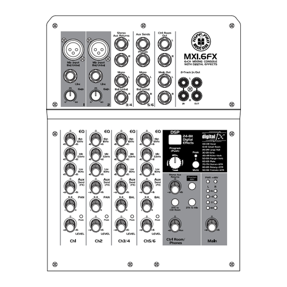
Hookup Diagram... - Page 6 FRONT PANEL 1- MIC INPUT MXi.6FX is equipped with 2 low-noise microphone preamplifiers with optional phantom power, 50 dB of Gain and 115 dB of S/N ratio. You can connect almost any type of microphone. Dynamic microphones do not need phantom power. Use phantom power only with condenser microphones but make sure that the phantom power button is disengaged before connecting the microphone.
- Page 7 9- TAPE IN Use the Tape input to connect a CD Player, Tape, DAT, iPOD or any other line-level source. You can send this signal either to CONTROL ROOM OUTPUT and/or to the MAIN MIX OUTPUT using the relative 2TK TO select buttons. 10- TAPE OUT These RCA jacks will route the main mix signal into a tape or DAT recorder.
- Page 8 MASTER SECTION 18- MAIN MIX LEVEL This knob controls the level of the signal sent to MAIN OUTPUTS and TAPE OUT. Also AUX RETURNS signals will be sent to this control. 19- PHONES/CONTROL ROOM LEVEL This knob controls the signal sent to CONTROL ROOM OUTPUT & PHONESOUTPUT. 20- OUTPUT LEVEL METERS These consist of two column of 4 LEDs each ranging from -20 dB to OL (CLIP).
-
Page 9: Installation Tips
29- PEAK/MUTE LED This LED lights up when the input signal is too strong or in case of the digital effect module being muted. 30- MUTE SWITCH This switch is used to activate/deactivate the effect facility. REAR PANEL 31- AC INPUT This connector is used to connect the supplied AC Adapter. -
Page 10: Wire Connections
Wire Connections... -
Page 11: Block Diagram
Block Diagram... -
Page 12: Preset List
Preset List... -
Page 13: Technical Specification
Technical Specification MXi.6FX MIXING CONSOLE... - Page 21 MXi.6FX...
- Page 22 MXi.6FX...
- Page 23 MXi.6FX...
- Page 28 MXi.6FX...
- Page 30 NF05176-1.0...
Need help?
Do you have a question about the MXI Series and is the answer not in the manual?
Questions and answers