Table of Contents
Advertisement
Available languages
Available languages
Quick Links
Advertisement
Table of Contents

Related Manuals for RR Electronic BISCAYA AIS


Summary of Contents for RR Electronic BISCAYA AIS
- Page 1 BISCAYA AIS EINBAUANLEITUNG MOUNTINGINSTRUCTIONS...
- Page 2 Wenn keines der angeschlossenen Empfangsgeräte in Betrieb ist, sollte die Stromversorgung für die Antennenanlage ausgeschaltet werden. Beim Betrieb der Antennenanlage BISCAYA AIS ist zu beachten, dass der AV 205 mit Strom versorgt wird, bevor (oder sobald) die daran angeschlossenen Empfangsgeräte eingeschaltet werden.
- Page 3 Die blau isolierte Stromversorgungsleitung des AV 403 wird mit dem Minuspol und die braun isolierte Leitung mit dem Pluspol des 12V- oder 24V-Bordnetzes verbunden. Die blau isolierte Stromversorgungsleitung des AV 205 wird mit dem Minuspol und die braun isolierte Leitung mit dem Pluspol des 12V- oder 24V-Bordnetzes verbunden. An der grün-gelben Leitung des Stromversorgungskabels ist der AV 205 unbedingt zu erden, bei einem Schiff mit Kunststoffrumpf ist ein außenliegender Erdschwamm zu verwenden.
- Page 4 Fehlersuchschema für Antennenanlage BISCAYA AIS Gesamte Antennenanlage ohne Funktion 1.1. Überprüfen der Stromversorgung – Spannung und Polarität an AV 403 und AV 205 1.2. Zuordnung der Antennenkabel zu den Antennen und zu den Antennenverteilern überprüfen, insbesondere auch an eventuell vorhandenen Trennstellen am Mastfuß. Zum Unterscheiden der Antennen kann der Widerstand incl.
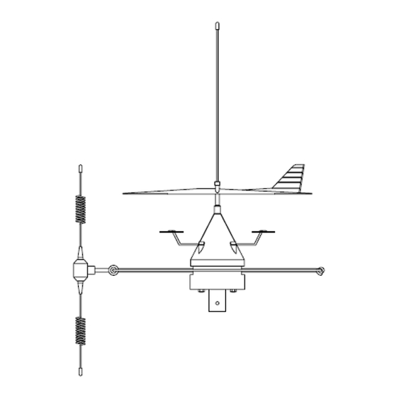
- Page 5 Installation of Antenna System BISCAYA AIS The antenna system BISCAYA AIS consists of the antennas DELTA 200 S and DELTA 22 M, which are mounted together building a unity. Antenna position: The antenna system BISCAYA AIS should be mounted at the mast-head. No other antennas should be mounted above the antenna system.
- Page 6 Installation of plug-in modules Two plug-in modules can be inserted into the distribution box AV 205. For retrofitting of plug-in modules, open the AV 205 case. The plug-in modules have 2 connection pins on one side and 3 pins on the other side. Insert the plug-in module into the sockets of the AV 205 main board with the 3 pin end of the module at the output side of the AV 205.
- Page 7 Trouble shooting of antenna system BISCAYA AIS No function of the entire antenna system 1.1. Check the power supply - voltage and polarity at the AV 403 and AV 205 1.2. Check the association of the antenna cables to the antennas, especially at the disconnecting points at the mastbottom.
- Page 8 Antenna System BISCAYA AIS Installation Diagram Specification subject to change without notice...
Need help?
Do you have a question about the BISCAYA AIS and is the answer not in the manual?
Questions and answers