Sign In
Upload
Download
Table of Contents
Contents
Add to my manuals
Delete from my manuals
Share
URL of this page:
HTML Link:
Bookmark this page
Add
Manual will be automatically added to "My Manuals"
Print this page
×
Bookmark added
×
Added to my manuals
Manuals
Brands
SnowEx Manuals
Spreader
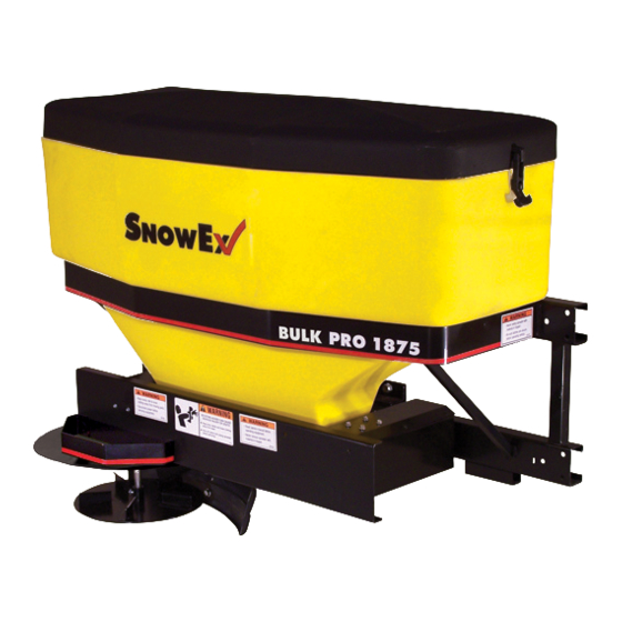
Bulk-Pro 1875
Manual
SnowEx Bulk-Pro 1875 Manual
Spreaders for snow & ice control
Hide thumbs
1
Table Of Contents
2
3
4
5
6
7
8
9
10
11
12
13
14
15
16
17
18
19
20
21
22
23
24
25
26
27
28
29
30
31
32
33
34
35
36
37
38
39
40
41
42
43
44
45
46
47
48
49
50
51
page
of
51
Go
/
51
Contents
Table of Contents
Troubleshooting
Bookmarks
Table of Contents
Table of Contents
Introduction
General Information and Registration
Safety Precautions
Spreader Parts/Diagrams
Wiring Instructions
Blank Page
Operating the Spreader
Adjustable Deflector
Gate Assembly
Vibrator Kit
Spreader Mount Parts/Diagrams
Trailer Mount
Drop Utility Mount
Troubleshooting
Spreader Maintenance
Warranty
Advertisement
Quick Links
1
Spreader Parts/Diagrams
2
Wiring Instructions
3
Operating the Spreader
4
Spreader Mount Parts/Diagrams
5
Troubleshooting
Download this manual
Spreaders for Snow & Ice Control
FOR MODELS
Bulk-Pro 1875
P
v i
t o
P -
o r
0 1
5 7
Mini-Pro 575
Junior 325
Rev. 05
© Trynex International 2009
L1040
(REV004)
7 — 1
Table of
Contents
Previous
Page
Next
Page
1
2
3
4
5
Advertisement
Table of Contents
Need help?
Do you have a question about the Bulk-Pro 1875 and is the answer not in the manual?
Ask a question
Questions and answers
Related Manuals for SnowEx Bulk-Pro 1875
Spreader SnowEx Pivot-Pro 1075 Manual
Spreaders for snow & ice control (51 pages)
Spreader SnowEx K1-131116 Owner's/Operator's Manual
(31 pages)
Spreader SnowEx Vee Pro 3000 Manual
For snow & ice control (43 pages)
Spreader SnowEx SP-8550 Owner's/Operator's Manual
(37 pages)
Spreader SnowEx V-Maxx G2 Owner's Manual
Hopper spreader (28 pages)
Spreader SnowEx 7500 Owner's And Operator's Manual
Spreaders for snow & ice control (41 pages)
Spreader SnowEx Bulk Pro SP-1575 Owner's Manual And Installation Instructions
Tailgate spreader (24 pages)
Spreader SnowEx Drop Pro 600 Owner's Manual
Drop spreader (24 pages)
Spreader SnowEx SR-210 Owner's Manual And Installation Instructions
Wireless tailgate spreader (24 pages)
Spreader SnowEx Tailgate Pro 575X Owner's Manual
Single-stage tailgate spreader (24 pages)
Spreader SnowEx SP-9300 Operator's Manual
Spreaders for snow & ice control (40 pages)
Spreader SnowEx Super Maxx SP-9300XH Owner's Manual And Installation Instructions
Hopper spreader (24 pages)
Spreader SnowEx SP-100-1 Owner's Manual
Tailgate spreader (22 pages)
Spreader SnowEx SP-9500X Owner's And Operator's Manual
(40 pages)
Spreader SnowEx Renegade S150A Owner's Manual
Hopper spreaders (40 pages)
This manual is also suitable for:
Pivot-pro 1075
Mini-pro 575
Junior 325
Table of Contents
Save PDF
Print
Rename the bookmark
Delete bookmark?
Delete from my manuals?
Login
Sign In
OR
Sign in with Facebook
Sign in with Google
Upload manual
Upload from disk
Upload from URL


Need help?
Do you have a question about the Bulk-Pro 1875 and is the answer not in the manual?
Questions and answers