Table of Contents

Related Manuals for I-Semble REVISED VERTICAL MURPHY BED


Summary of Contents for I-Semble REVISED VERTICAL MURPHY BED
- Page 1 REVISED VERTICAL MURPHY BED HARDWARE KIT INSTRUCTIONS Revised November 2017 Review instructions fully prior to use for important safety information. Always check Rockler.com to confirm that you are using the most recent version for your product.
- Page 2 GENERAL SAFETY WARNINGS This product is designed for specific applications as defined in the instructions and should not be modified and/or used for any other applications. Before using the Vertical I-Semble ® Murphy Bed Hardware Kits, read, understand and follow all instructions and safety information provided. KEEP THESE INSTRUCTIONS FOR FUTURE REFERENCE.
- Page 3 > Do NOT install against brick or masonry walls or walls with metal studs. > You MUST have another ADULT help you while installing your I-Semble ® wall bed unit to make sure the bed doesn’t > Do NOT use an impact driver to drive fasteners; the added close inadvertently while you are working.
- Page 4 PARTS LIST Twin Qty. Full Qty. Queen Qty. A Left and Right Frame Sides (with Pivot Points) B Upper and Lower Half Frame Supports C Middle Frame Supports D Long Center Frame Support E Upper and Lower Frame Supports Flat Bars G1 Pistons H Mattress Supports Mounting Plate (Left and Right)
- Page 5 Twin Qty. Full Qty. Queen Qty. S2 #5 Allen Key Threaded Inserts U M8 x 16mm Hex Head Screws V #10 x 55mm Flathead Screws W #8 x 15mm Washer Head Screws M5 x 15mm Machine Screw AA M6 x 30mm Bolts BB M8 x 50mm Bolts DD Nylon Washers for Legs EE M5 Nuts (for Saddle Lock)
- Page 6 CABINET PARTS (NOT INCLUDED) > Do NOT construct the cabinet from MDF, particleboard or melamine-coated MDF. > Do NOT modify design to remove Upper and Lower Headboards (3 and 4) These parts serve an important safety function. MINIMUM INTERIOR OPENING SIZES Width Height Depth...
- Page 7 REQUIRED TOOLS (NOT INCLUDED) Drill Circular Saw Stud Finder Tape Measure or Table Saw Pencil 3/8" Nut Driver or Phillips Screwdriver #8 Countersink Bit Socket Wrench 13/64" Drill Bit 5/16" Drill Bit 3/16" Drill Bit 5/32" Drill Bit 3/8" Drill Bit REQUIRED HARDWARE (NOT INCLUDED) #8 x 2"...
- Page 8 Left Right Cabinet Cabinet ⁄ " ⁄ " Front Front Side Side Edge Edge ⁄ " ⁄ " ⁄ " ⁄ " ⁄ " ⁄ " ⁄ " ⁄ " ⁄ " ⁄ " ⁄ " ⁄ " ⁄ " ⁄...
- Page 9 Side View Dowel Rods Front View Screws Side View Front View Fig. 2 - Top and Upper Headboard/Bottom and Lower Headboard Assemblies Recommended Cabinet Assembly (Parts Not Included) 2. While the Top (2) and Upper Headboard (3) are clamped in place, drill and countersink (if desired) pilot holes for #8 x 2"...
- Page 10 Dowel Rods Screws Top Down View Dowel Rods Screws Bottom Up View Front View Fig. 3 5. Assemble the Top (2) with the Upper Headboard (3) 9. Move to the bottom of the right Side (1) and mark and the Bottom (2) with the Lower Headboard (4). locations for two dowels across the bottom edge of Spread glue on the edges of the headboards that join the right Side and bottom face of the Bottom (2).
- Page 11 To avoid Stud Locations the risk of serious injury, you MUST locate wooden Lag Bolt studs in your wall using a Locations stud finder and install lag bolts securely into them. Stud and lag bolt locations in this image are for illustration purpose only.
- Page 12 Install the Wall Brackets > Each Wall Bracket (HH) MUST be mounted flush on the cabinet top and flush to the wall with no gap with all six screws. Failure to do so increases the risk of cabinet failure and serious personal injury. 1.
- Page 13 Pivot Point Pivot Point Frame Exploded View Assemble the Bed Frame All steps in this section use Frame Exploded View. 4. Attach a Flat Bar (F) and an Upper/Lower Frame Support (E) to each end of the Long Center Frame Support (D), using M8 x 50mm bolts (BB) and M8 Make sure that the mounting plates of Lock Nuts (FF).
- Page 14 Install the Slats 1. Start at the head of the bed, nearest the pivot points on the Left/Right Sides of the Frame (A). 2. Take two Slats (O) and place a Slat Cap (P) on one end of each. Connect them by inserting the other ends in a Double Slat Cap (Q).
- Page 15 Install the Frame in the Cabinet Bed Frame > To avoid the risk of serious injury, Do NOT unscrew the bed cabinet from the wall once the pistons are in place. 1. Attach the Pistons (G1) to the bed frame on each side by fitting the opening on the end with the internal rod onto the threaded stud beyond the pivot point at the head of the frame.
- Page 16 5. Pull the top of the bed frame out beyond the front of the cabinet and install the Temporary Stops (GG) on the top corners of the cabinet. Fig. 14. 6. Position the Permanent Stop (6) where you want to install it.
- Page 17 6" 6" 6" 6" 10" 10" ⁄ " ⁄ " Back of Back of Door Panel Door Panel Measurements are for the placement of ⁄ " ⁄ " this hole Twin and Full Bed Door Panel Queen Bed Door Panel (2 Panels required for Full Bed) (2 Panels required for Queen Bed) Fig.
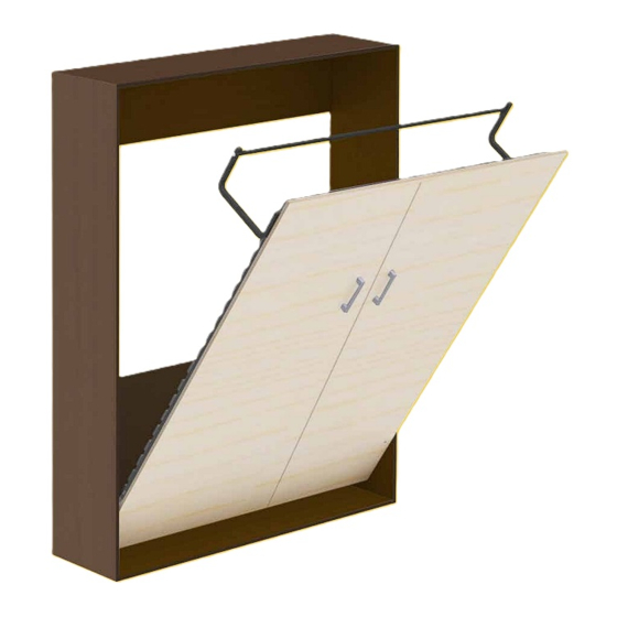
- Page 18 4. Hook the Door Panel(s) (5) onto the frame and push down until they are firmly in place. Center and fine-tune the position of the Door Panel(s). Fig. 17. The bed will not stay down without the weight of a mattress. You MUST have an adult helper hold down the bed to avoid the risk of serious injury from the bed suddenly slamming shut.
- Page 19 Fig. 19 Fig. 20...
- Page 20 Wall Brackets (HH) Stud and lag bolt locations Stud Locations bolted into wooden in this image are for wall studs illustration purpose only. 1/4" x 3" Washer Head Lag Bolts (KK) installed through Upper Headboard into wooden wall studs Locations for 1/4" x 3" Washer Head Lag Bolts (KK) installed through Lower Headboard into wooden...
Need help?
Do you have a question about the REVISED VERTICAL MURPHY BED and is the answer not in the manual?
Questions and answers