Rice Lake 920i Series Installation Instructions Manual
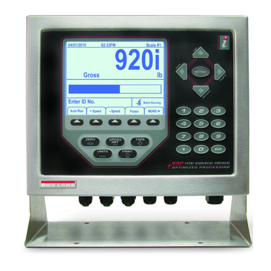
Programmable hmi indicator/controller
Hide thumbs
Also See for 920i Series:
- Installation instructions (4 pages) ,
- Installation (4 pages) ,
- Operation manual (34 pages)
Table of Contents

Subscribe to Our Youtube Channel
Related Manuals for Rice Lake 920i Series


Summary of Contents for Rice Lake 920i Series
- Page 1 Presented By Dallas Ft Worth Austin Houston NicolScales.com 800.225.8181 Contact Us Nicol Scales & Measurement is an ISO Accredited Calibration Company that has provided calibration, repair and sales of all types of weighing and measurement products since 1931.
- Page 2 ® 920i Programmable HMI Indicator/Controller Wall Mount Enclosure Installation Instructions PNs 69763, 69765, 69770, 69776, 72133, 72134 This document contains drawings, replacement parts lists, and instructions for installing wall mount models indicators. See the Installation Manual, 920i 920i • Use a wrist strap to ground yourself and protect PN 67887, for general installation and configuration components from electrostatic discharge (ESD) when and calibration information.
-
Page 3: Cable Grounding
Wall mount models of the provide eleven cord nuts. 920i grips for cabling into the indicator. The parts kit • Finish installation using cable ties to secure includes cord grip plugs to prevent moisture from cables inside of indicator enclosure. entering the enclosure. -
Page 4: Replacement Parts And Assembly Drawings
Replacement Parts and Assembly Drawings Table 2 lists replacement parts for the desktop and universal models, including all parts referenced in Figures 920i 3 through 6. See Figure Number Description (Quantity) 68902 Enclosure, wallmount (1) 68598 Protective lens (1) 67614 LCD display (1) 15134 Lock washers, No. - Page 5 See Figure Number Description (Quantity) 68724 Cover gasket (1) 117930 CPU board (1); Board marked as 109549; sold as PN 117930 Cable tie mounts, 3/4 in. (6) 15650 16861 High voltage warning label (1) 16892 Ground/Earth label (1) 68621 Fuse access coverplate gasket (1) 68903 Back panel (1) —...
- Page 6 51/6X 4/3X 5/3X 30/4X (13) 27/6X 26/2X (13) 25/2X 23/3X 24/2X 21/4X 20/2X 22/4X (12) (11) 16/11X 15/4X 12/8X 13/11X 11/8X Figure 3. Wall Mount Enclosure...
- Page 7 39/11X 40/11X 42/3X 43/2X FUSES F1 & F2 Figure 4. Wall Mount Enclosure, Bottom View (28) FROM DISPLAY BOARD BLACK WIRE GROUND WIRE RED WIRE GREEN WIRE (28) (29) (13) FROM SWITCH MEMBRANE (13) FROM DISPLAY BOARD Figure 5. Wall Mount Enclosure, CPU Board Connections Figure 6.
Need help?
Do you have a question about the 920i Series and is the answer not in the manual?
Questions and answers