Rice Lake 920i Series Installation Instructions
Two-card expansion board
Hide thumbs
Also See for 920i Series:
- Installation (4 pages) ,
- Installation instructions manual (7 pages) ,
- Operation manual (34 pages)
Advertisement
Quick Links
®
920i
Programmable HMI Indicator/Controller
Two-Card Expansion Board Installation Instructions
PNs 69782 and 71743
This document contains procedures for installing
two-card expansion boards in the wall and panel
mount models of
indicators. Procedures for each
920i
enclosure type are described separately below.
See the Installation Manual, PN 67887, for general
installation and configuration information, including
option card slot numbering and port assignments.
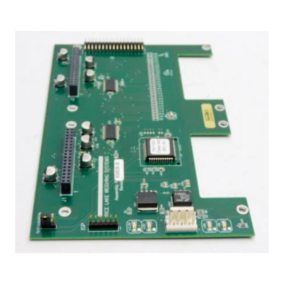
The slot/location jumper on the two-card
NOTE:
expansion board must be set to the 3–4 position for all
standard installations. The 9–10 position is used only
in special applications using both six- and two-card
expansion boards.
J1
ISP
1
+3.3V
+5V
–6V
J4
1
+6V
+6V
–6V
April 2007
For applications using both six- and two-card
expansion boards, connect the six-card board to the
two-card board using either cable PN 71799 (panel
mount units) or PN 71780 (wall mount units).
U3
GND
Figure 1. Two-Card Expansion Board
Disconnect power before opening indicator
enclosure.
Option
cards
are
Disconnect power to the expansion board
before installing option cards.
Use a wrist strap to ground yourself and
protect components from electrostatic
discharge (ESD) when working with circuit
boards.
SLOT/LOCATION JUMPER
9–10
3–4
J2
not
hot-pluggable.
1
J3
71284
Advertisement

Subscribe to Our Youtube Channel
Related Manuals for Rice Lake 920i Series


Summary of Contents for Rice Lake 920i Series
- Page 1 ® 920i Programmable HMI Indicator/Controller Two-Card Expansion Board Installation Instructions PNs 69782 and 71743 This document contains procedures for installing For applications using both six- and two-card two-card expansion boards in the wall and panel expansion boards, connect the six-card board to the mount models of indicators.
- Page 2 Panel Mount Installation (71743) former screw locations at bottom edge of option cards. Use the following procedure to install the two-card 8. Install 3/4" standoff (PN 98807) on top of expansion board in the panel mount enclosure. See option card in slot 1, threading into 1/2" Figure 2 for locations of option kit components.
- Page 3 Wall Mount Installation (69782) cable clamps and extend cable to full length. (Ribbon cable attaches to right side of installed Use the following procedure to install the two-card expansion board. See Figure 4 on page 4). expansion board in the wall mount enclosure. See 7.
- Page 4 TWO-CARD EXPANSION BOARD RIBBON CABLE OPTION CARDS POWER SUPPLY CABLE TO EXPANSION BOARD POWER SUPPLY CABLE TO CPU BOARD POWER SUPPLY Figure 4. Two-Card Expansion Board Installed in Wall Mount Enclosure Installing Option Cards Each option card is shipped with installation 3.
Need help?
Do you have a question about the 920i Series and is the answer not in the manual?
Questions and answers