Rice Lake 720i Technical Manual
Programmable weight indicator/controller
Hide thumbs
Also See for 720i:
- Installation manual ,
- Installation (4 pages) ,
- Options installation (16 pages)

Related Manuals for Rice Lake 720i


Summary of Contents for Rice Lake 720i
- Page 1 Programmable Weight Indicator/Controller 720i Firmware Version 2 720iB (Batching) Firmware Version 1 Technical Manual August 5, 2024 PN 103121 Rev I...
- Page 2 All information contained within this publication is, to the best of our knowledge, complete and accurate at the time of publication. Rice Lake Weighing Systems reserves the right to make changes to the technology, features, specifications and design of the equipment without notice.
- Page 3 August 5, 2024 Added setpoint routine examples Table i. Revision Letter History Technical training seminars are available through Rice Lake Weighing Systems. Course descriptions and dates can be viewed at www.ricelake.com/training or obtained by calling 715-234-9171 and asking for the training department.
-
Page 4: Table Of Contents
3.10 CPU Board Removal................. 24 Rice Lake continually offers web-based video training on a growing selection of product-related topics at no cost. - Page 5 Batch and Continuous Setpoints............... . 79 Technical training seminars are available through Rice Lake Weighing Systems.
- Page 6 14.0 Specifications ............... . 131 Rice Lake continually offers web-based video training on a growing selection of product-related topics at no cost.
-
Page 7: Introduction
This manual is intended for use by service technicians responsible for installing and servicing 720i digital weight indicators. This manual applies to Version 2.00 of the 720i indicator software and Version 1.01 of the 720i batching indicator software. Configuration and calibration of the indicator can be accomplished using the Revolution configuration utility, serial commands or the indicator front panel keys. -
Page 8: Overview
720i Programmable Weight Indicator/Controller Overview The 720i is a single-channel programmable digital weight indicator/controller. The 720i can be loaded with PCE software or 720i batching software. Refer to Section 9.0 on page 79 Section 10.0 on page 95 for further information on software choices. -
Page 9: System Configurations
System Configurations All models include a CPU board with one option card slot. The 720i is a single scale unit and cannot be upgraded to a multi- channel A/D. The 720 is provided with either the PCE firmware, which includes Truck In/Out programs or as Batching firmware for setpoint control. -
Page 10: Operation
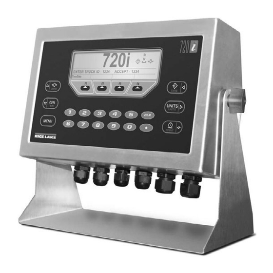
720i Programmable Weight Indicator/Controller Operation This section provides an overview of 720i Programmable HMI Indicator/Controller operation instructions. The 720i universal model front panel consists of a 22-button keypad with an LCD display (Figure 2-1). The keys are grouped as four configurable softkeys, four scale function/navigation keys, Menu and Print/Enter keys, and numeric entry keys. The panel mount front panel consists of a 10-button keypad with an LCD display. -
Page 11: Operating Modes
Inserts a decimal point as needed Table 2-1. Front Panel Operating Modes The 720i has two modes of operation, Weigh Mode and Setup Mode. See the following information for an overview of Weigh Mode and Setup Mode. 2.1.1 Weigh Mode The indicator displays gross, net, or tare weights as required to indicate scale status and the type of weight value displayed. -
Page 12: Zero Scale
ACCFMT print format (Section 7.0 on page 65). Press the Clear key twice to clear the accumulator. NOTE: With the panel mount version of the 720i, use CLR Accumulator DigIn Function to clear the accumulator. www.RiceLake.com Visit our website... -
Page 13: Softkey Operations
For applications with more than three defined softkeys, the More… key is automatically assigned to the fourth softkey position; Press More… to toggle between groups of softkeys *Truck Modes 1-6 only **720i Batching Version software only ***Advance Truck Mode only Table 2-2. Configurable Softkeys © Rice Lake Weighing Systems ● All Rights Reserved... -
Page 14: Installation
• Use a grounding wrist strap to protect components from electrostatic discharge (ESD) damage when working inside the product enclosure. • The power cord serves as the power disconnect for the 720i. Ensure the power cord is unplugged prior to opening the enclosure. The power outlet must be near the equipment and must be easily accessible. -
Page 15: Cable Connections
Cable Connections The universal model of the 720i provides six cord grips for cabling into the indicator: one for the power cord and five to accommodate other cabling. Install plugs in all unused cord grips to prevent moisture from entering the enclosure. -
Page 16: Serial Communications
3.3.2 Serial Communications Communications ports on the 720i CPU board support full duplex RS-232 and 20 mA output communications at up to 115200 bps. Optional communications cards support USB, and Ethernet connections to the 720i. 1. To attach serial communications cables, route the cable through the cord grip and ground the shield wire as described Section 3.6 on page... -
Page 17: Digital I/O
3.3.4 Detached Display Module (DDM) Table 3-6 shows the connections between connector J4 on the 720i CPU board and connector J3 (Com 1) on the detached display module (DDM) board. See board diagrams in Figure 3-2 on page 18 Figure 3-3 on page... -
Page 18: Installing Option Cards
7. When installation is complete, reassemble the enclosure as described in Section 3.7 on page The 720i automatically recognizes all installed option cards when the unit is powered on. No hardware-specific configuration is required to identify the newly installed card to the system. -
Page 19: Slot Assignments
4. Mark the cables to remove insulation and shield (Section 3.6.1 on page 20). 5. Route stripped cables through the cord grips and grounding clamps. 6. Ensure the shields contact the grounding clamps and tighten the ground clamp screws. © Rice Lake Weighing Systems ● All Rights Reserved... -
Page 20: Stripping Cables
Torque backplate screws to 15 in-lb (1.7 N-m) Figure 3-6. 720i Enclosure Backplate IMPORTANT: Torqued screws may become less tight as the gasket is compressed during torque pattern, therefore a second torque is required using the same pattern and torque value. -
Page 21: Panel Mount Installation
Installation Panel Mount Installation This section includes instructions for installation of the 720i panel mount indicator. 3.8.1 Panel Mount Cutout Dimensions 7.35" Outer Perimeter of 6.25" Exterior Faceplate (Solid Line) Panel Cutout 6.11" (Dashed Line) 3.88" 2.47" 2.60" Interior Housing... -
Page 22: Panel Mount Controller Installation
Section 3.3 on page 15 for details on the available 720i CPU board ports. 1. Use the panel mount cable (PN 105348) with 6-pin connectors on both ends to connect the display to the controller. 2. Earth ground the panel mount controller using the grounding stud next to the power connector. -
Page 23: Legal For Trade Sealing
The device also has a category 2 audit trail that is accessed through the keyboard. There are two event counters • Calibration • Configuration Universal Mount For proper sealing of the 720i Universal Mount, see Figure 3-12. Fillister Screw Sealing Wire... -
Page 24: Cpu Board Removal
720i Programmable Weight Indicator/Controller 3.10 CPU Board Removal If the 720i CPU board must be removed, use the following procedure: 1. Disconnect power to the indicator. 2. Remove the backplate as described in Section 3.2 on page 3. Unplug connectors for power to the board, serial communications, digital I/O and installed option cards. -
Page 25: Replacement Parts And Assembly Drawings
3.12 Replacement Parts and Assembly Drawings See the following information for replacement parts and assembly drawings. 3.12.1 Universal Model Table 3-8 on page 27 lists replacement parts and parts kit contents for the 720i universal enclosure model, including all parts referenced in Figure 3-14 through Figure 3-16 on page Figure 3-14. - Page 26 720i Programmable Weight Indicator/Controller From Power Supply Figure 3-15. 720i Universal Model, CPU Board and Backplate Ground wire (13) to backplate (22) Ground wire from Grounding Stack power cord (15) Figure 3-16. 720i Universal Model, Grounding Detail www.RiceLake.com Visit our website...
- Page 27 Figure 3-15 on page 26 — 103458 Ribbon Cable Assembly, 7'', 20-pin Female, Universal – — 103609 Cable Assembly, CPU-to-Display, Universal – * Additional parts included in parts kit Table 3-8. Universal Model Replacement Parts © Rice Lake Weighing Systems ● All Rights Reserved...
- Page 28 720i Programmable Weight Indicator/Controller Item No. Part No. Description Qty. See Figure Universal Model Parts Kit Contents 104033 720i Software Tool Kit CD – 103988 Tilt Stand Washer – 103610 Tilt Stand Knob – 42149 Rubber Feet, Tilt Stand –...
-
Page 29: Panel Mount Display
Installation 3.12.2 Panel Mount Display Table 3-9 lists replacement parts and parts kit contents for the 720i panel mount remote display unit, including all parts referenced in Figure 3-17. Figure 3-17. 720i Panel Mount Display Assembly Item No. Part No. -
Page 30: Panel Mount Controller
720i Programmable Weight Indicator/Controller 3.12.3 Panel Mount Controller Table 3-10 on page 31 lists replacement parts and parts kit contents for the 720i panel mount controller, including all parts referenced in Figure 3-18. Figure 3-18. Panel Mount Controller Assembly www.RiceLake.com... - Page 31 Lock Washers, No. 8 Type A 15694 No. 8 Crimp Connector 53075 Cable Shield Ground Clamps 30623 Machine Screw, Fillister Head, 8-32NC x 7/16 94422 Capacity Label Table 3-10. Panel Mount Controller Replacement Parts © Rice Lake Weighing Systems ● All Rights Reserved...
-
Page 32: Configuration
This section provides an overview of 720i Programmable HMI Indicator/Controller configuration instructions. To configure the 720i indicator, press the Menu key on the front panel (only if jumper J9 is installed), press the Down key to select Configuration then press Enter. Detailed descriptions of the configuration menus are provided in Section 4.2 on page... -
Page 33: Serial Command Configuration
4.1.3 Front Panel Configuration By default, the 720i is configured to use the installed single-channel A/D as the source for Scale 1. To configure the 720i for serial scale support, use the Config submenu under the Scales menu. For example: to configure a serial scale, set the serial input function (SERIAL menu) for Port 4 (or Port 7, if using a serial 46). -
Page 34: Menu Structures And Parameter Descriptions
Example: Range 1 is 0-30 x 0.01 lb; Range 2 is 30 - 60 x 0.02 lbs. Menu Structures and Parameter Descriptions The 720i indicator can be configured using a series of menus accessed through the indicator front panel when the indicator is in setup mode. -
Page 35: Menu Navigation
When moving through the menu parameters, the default or previously selected value appears first on the display. © Rice Lake Weighing Systems ● All Rights Reserved... -
Page 36: Scales Menu
720i Programmable Weight Indicator/Controller 4.2.2 SCALES Menu The SCALES menu is shown in Figure 4-6. The FORMAT submenu is shown in Figure 4-7 on page 39. The CALIBR submenu is shown in Figure 4-9 on page 45. Parameters shown in each diagram are described in the table following that diagram. - Page 37 NOTE: When configuring non-A/D scales, set the DIGFLTx parameters to 1 to disable filtering. Section 12.7 on page 122 for more information about digital filtering Table 4-3. SCALES Menu Parameters © Rice Lake Weighing Systems ● All Rights Reserved...
- Page 38 720i Programmable Weight Indicator/Controller SCALES Menu Parameter Choices Description DFSENS 2OUT Digital filter cutout sensitivity; Specifies the number of consecutive readings that must fall outside the filter 4OUT threshold (DFTHRH parameter) before digital filtering is suspended; See Section 12.7 on page 122...
- Page 39 8.888888 8.888888 88.88888 88.88888 888.8888 troyoz 888.8888 8888.888 troylb 8888.888 88888.88 88888.88 888888.8 CUSTOM NONE UNITS INTERVL REFRESH 0.100000 number number HOUR Figure 4-7. SCALES Menu, FORMAT Submenu, SPLIT = OFF © Rice Lake Weighing Systems ● All Rights Reserved...
- Page 40 720i Programmable Weight Indicator/Controller SCALES Menu, FORMAT Submenu, SPLIT = OFF Parameter Choices Description Level 4 FORMAT Submenus PRIMAR DECPNT Specifies the decimal position, display divisions, and units used for the primary units; DSPDIV See Level 5 submenu parameter descriptions...
- Page 41 8.888888 88.88888 888.8888 8888.888 88888.88 888888.8 DSPDIV Display divisions; Selects the minimum division size for the ROC units displayed weight Table 4-4. SCALES Menu, FORMAT Submenu Parameters, SPLIT = OFF (Continued) © Rice Lake Weighing Systems ● All Rights Reserved...
- Page 42 720i Programmable Weight Indicator/Controller SCALES Menu, FORMAT Submenu, SPLIT = OFF Parameter Choices Description MULT Multiplier; Specifies the conversion factor by which the primary units are multiplied by to obtain the displayed rate of change 0.000001– units; See Section 12.8 on page 123...
- Page 43 10000 8888888 weight 8888880 8888800 8.888888 88.88888 888.8888 troyoz 8888.888 troylb If SPLIT = 3RNG or 3INTVL 88888.88 CUSTOM NONE Figure 4-8. FORMAT Submenu, SPLIT OFF (Multi-range and Multi-interval Scales) © Rice Lake Weighing Systems ● All Rights Reserved...
- Page 44 720i Programmable Weight Indicator/Controller SCALES Menu, FORMAT Submenu, SPLIT OFF Parameter Choices Description Level 4 FORMAT Submenus DECPT1 8888888 Decimal point location for first range or interval; Specifies the location of the decimal point or dummy zeros in 8888880 the primary unit display;...
- Page 45 NOTE: Use this parameter only after WZERO and WSPAN have been set. See Section 5.2 on page 61 for more information about using this parameter. Table 4-6. SCALES Menu, CALIBR Submenu Parameters © Rice Lake Weighing Systems ● All Rights Reserved...
-
Page 46: Serial Menu
720i Programmable Weight Indicator/Controller 4.2.3 SERIAL Menu Section 12.6 on page 121 for information about 720i serial data formats. SCALES SERIAL FEATURE PFORMT SETPTS DIG I/O ALGOUT VERS 720i Batching Version only see page 57 PORT 2 BAUD BITS TERMIN... - Page 47 If PORT = CMD INDUST 720i Batching Version only 4KEYS Selectable token characters KEYPAD If STREAM = LFT or INDUST DISPLAY If PORT = CMD Figure 4-11. SERIAL Menu, Port 4 and Expansion Ports © Rice Lake Weighing Systems ● All Rights Reserved...
- Page 48 IND SC:Industrial (non-legal-for-trade) scale input KEYBD is available only on Port 1; SCALE, IND SC are available only on Port 4 and higher (expansion ports) NOTE: The keyboard interface is not hot-pluggable. Power-off the 720i before attaching keyboard cable to the Port 1 connector.
- Page 49 NOTE: Streaming is not supported for RS-485 connections. The print key always prints locally. SFMT Format Specifies the stream format used for the streamed data (CMD scale type); The default format is the Rice Lake format (Section 12.6 on page 121);...
-
Page 50: Feature Menu
720i Programmable Weight Indicator/Controller 4.2.4 FEATURE Menu The FEATURE menu is used to set miscellaneous system attributes, including time and date, truck mode, softkey definitions, and parameters relating to the regulatory environment. See Table 4-8 on page 51 for parameter descriptions. - Page 51 Keyboard lock; Specify ON to disable the keypad in normal mode ZERONLY Zero key only; Specify ON to disable all front panel keys except ZERO in normal mode Table 4-8. FEATURE Menu Parameters © Rice Lake Weighing Systems ● All Rights Reserved...
- Page 52 Display Tare Display Accum Display ROC Alibi Setpoint These features are only available with the 720i Batching version software Batch Start Batch Stop Batch Pause Batch Reset Weigh These features are available with the Advanced Truck Mode Only...
- Page 53 Specifies the shift start and end time in 24 hour format (HHMMSS) SHIFT # END DAY START HHMMSS Specifies the day start and end time in 24 hour format (HHMMSS) DAY END HHMMSS Table 4-8. FEATURE Menu Parameters (Continued) © Rice Lake Weighing Systems ● All Rights Reserved...
- Page 54 720i Programmable Weight Indicator/Controller FEATURE Menu, REGULAT/INDUST Submenu The INDUST setting of the REGULAT parameter allows customization of several tare, clear, and print functions for use in non-legal-for-trade scale installations. See Section 12.2 on page 116 for more information about regulatory mode functions.
-
Page 55: Pformt Menu
ACCFMT SPFMT TRWIN TRWOUT TRFMT ALERT See GFMT Menu HDRFMT1 HDRFMT2 AUXFMT PORT AUX1FMT AUX20FMT PORT 4 PORT Same as AUXFMT1 PORT 2 PORT 4 PORT 2 Figure 4-14. PFORMT Menu © Rice Lake Weighing Systems ● All Rights Reserved... -
Page 56: Dig I/O Menu
720i Programmable Weight Indicator/Controller 4.2.6 DIG I/O Menu The DIG I/O menu shown in Figure 4-15 is used to assign functions to digital inputs and outputs. SLOT 0 represents the eight I/ O bits available on the CPU board (connector J6). The additional slot, with 24 I/O bits, is shown only if the digital I/O expansion card is installed. - Page 57 • CLRTAR clears the current tare for the active scale *BATRUN • CLRACC clears the active accumulator *BATSTRT *BATPAUS *BATRESET *BATSTOP CLRCN GROSS PRIM CLRTAR CLRACC * 720i Batching Software Version Only Table 4-10. DIG I/O Menu Parameters © Rice Lake Weighing Systems ● All Rights Reserved...
-
Page 58: Algout Menu
720i Programmable Weight Indicator/Controller 4.2.7 ALGOUT Menu If the analog output option is installed, configure all other indicator functions and calibrate the indicator itself before configuring the analog output. See the Analog Output Card Installation Instructions, PN 69089, for more information. -
Page 59: Fldbus Menu
SCALES SERIAL FEATURE PFORMT SETPTS DIG I/O ALGOUT VERS 720i Batching Version only Software see page 57 version Figure 4-18. Version Menu © Rice Lake Weighing Systems ● All Rights Reserved... -
Page 60: Calibration
Figure 5-1. Calibration (CALIBR) Submenu Gravity Compensation Gravity compensation for latitude and elevation is available for the 720i. To calibrate with gravity compensation, the LOCALE parameter under the FEATURE menu must be set ON, and the LATUDE (latitude) and ELEVAT (elevation, in meters) -
Page 61: Front Panel Calibration
Calibration Front Panel Calibration The CALIBR submenu (within the SCALES menu) is used to calibrate the 720i (Figure 5-2). WZERO 1440 Calibrate + / - Last Zero Figure 5-2. WZERO Calibration Display The zero, span, and linear calibration point displays provide a set of softkeys used specifically for calibration procedures: +/–... -
Page 62: Serial Command Calibration
Revolution utility. With the 720i connected to the PC: 1. Select New from the File menu. 2. The Select Indicator dialog box appears. Select the 720i icon and click OK. 3. Select Connect from the Communications menu. 4. Select Scale from the left-side menu and then click the Scale icon. -
Page 63: Using Revolution
Open the Revolution program and select file/new. Then select the 720i icon or the 720i Batching icon and press OK. Connect the PC serial port to port 2 of the 720i then click on the Connect icon in the tool bar. Revolution attempts to establish communications to the indicator. -
Page 64: Installing Software Upgrades
New 720i software can be downloaded and installed using an internet connection and the Rice Lake iSeries Update Utility. The Rice Lake iSeries Update Utility is installed with the iRev application. The iRev installer can be found on the Rice Lake website. -
Page 65: Print Formatting
This section provides an overview of 720i Programmable HMI Indicator/Controller print formatting instructions. The 720i provides print formats that determine the format of the printed output when the PRINT key is pressed, a KPRINT serial command is received, or when truck weigh-in or weigh-out operations are performed. Supported print formats are: GFMT, NFMT, ACCFMT, SPFMT, SETPNT, TRWIN, TRWOUT, ALERT, and AUXFMT1—AUXFMT20. - Page 66 720i Programmable Weight Indicator/Controller Command Description Supported Ticket Formats Setpoint Commands <SCV> Setpoint captured value SPFMT <SN> Setpoint number <SNA> Setpoint name <SPM> Setpoint mode (gross or net label) <SPV> Setpoint preact value <STV> Setpoint target value Auditing Commands <CD>...
-
Page 67: Default Print Formats
Table 7-2 has the default print formats for the 720i and lists the conditions under which each print format is used. HDRFMT1 and HDRFMT2 formats are used to specify header information that can be used by the other ticket formats. -
Page 68: Customizing Print Formats
720i Programmable Weight Indicator/Controller Customizing Print Formats The following sections describe procedures for customizing print formats using the Revolution configuration utility or serial commands. See Section 12.5 on page 119 for information about custom stream formatting. 7.3.1 Using Revolution The Revolution configuration utility provides a ticket formatting grid with a tool bar. The grid allows ticket formating without using the formatting commands (<NL>, <SP>, etc.) required by the front panel or serial command methods. -
Page 69: Using The Front Panel
• To add a special character, insert the < and > delimiter characters from the selection list; Use the numeric keypad to insert the decimal ASCII value (1–255) of the character between the delimiters Example: Insert <2> to add the STX character to the print format. © Rice Lake Weighing Systems ● All Rights Reserved... -
Page 70: Using Serial Commands
<H1> or <H2> print format commands. 7.3.3 Using Serial Commands With a personal computer, terminal or remote keyboard attached to one of the 720i serial ports, use the serial command set described in Table 7-1 on page 65 to customize the print format strings. -
Page 71: Truck Modes
Truck Modes Truck Modes This section provides an overview of 720i Programmable HMI Indicator/Controller truck mode instructions. Features The truck in/out modes are used to handle multiple truck ID numbers and weights. Truck IDs can be up to 16 alphanumeric characters in length. -
Page 72: Using The Truck Regs Display
720i Programmable Weight Indicator/Controller Using the Truck Regs Display The Truck Regs display by pressing the Truck Regs softkey in weighing mode. The display contains an alphabetical list of stored truck IDs, weigh-in weights (in primary units), and the time and date of the weigh-in transaction (Figure 8-2). -
Page 73: Single-Transaction Tare Weights And Ids
Management – Add and remove materials, customers, and source IDs and names. While in a submenu the Tare key can be pressed to go back to the previous menu. On Weigh-In the AUX1FMT is printed. On Weight-Out the AUX2FMT is printed. © Rice Lake Weighing Systems ● All Rights Reserved... - Page 74 720i Programmable Weight Indicator/Controller When printing Shift/Day and Detail All/Pending reports: • AUX3FMT is the header • AUX4FMT is each line for each transaction • AUX5FMT is the footer/total lines When printing Summary Reports: • AUX6FMT is the header • AUX7FMT is the header for Source Reports •...
- Page 75 Table 8-5. Default Print Formats for Advanced Truck NOTE: If Advance Mode features are turned off, the field should be removed from the Print Format, otherwise a blank field is printed (Table 8-3 on page 74). © Rice Lake Weighing Systems ● All Rights Reserved...
- Page 76 2. Press the Weigh softkey, enter the ID, and press the Enter key. 3. Indicator generates the weigh-out ticket. NOTE: The truck may be empty or loaded for either of the above procedures. The 720i calculates the proper net weight. Advance Mode Keyed Tare If the truck tare weight is known, Advance Mode keyed tare allows for both weigh-in and weigh-out to be performed in one transaction.
-
Page 77: Advance Mode Menus
Specifies the source of the Summary Report SINGLE ID – Prints all shifts for the Daily Report SHIFT SHIFT 1 Prints select shifts for the Daily Report SHIFT 2 SHIFT 3 Table 8-6. Reports Menu Parameters © Rice Lake Weighing Systems ● All Rights Reserved... - Page 78 720i Programmable Weight Indicator/Controller Advance Mode Management Menu In Advance Mode the Weigh, Reports and Management softkeys are enabled. The Management softkey is described below. NOTE: While in a submenu the TARE key can be pressed to go back to the previous menu.
-
Page 79: Setpoints
A digital output or function assigned to a free-running setpoint continuously changes state, becoming active or inactive, as defined by the setpoint parameters. Batch setpoints – are active one at a time, in an ordered sequence. The 720i can use setpoints to control up to 32 separate batch processing steps. - Page 80 720i Programmable Weight Indicator/Controller Kind Description Batch Continuous %REL Percent relative setpoint; Performs functions based on a specified percentage of the target value of a referenced setpoint, using the same weight mode as the referenced setpoint; The actual target value of the...
-
Page 81: Setpoint Menu Parameters
Go to B Go to C INMOTON INRANGE BATCHPR TIMER CONCUR Go to E Go to D NEVER DELTA CHKWEI ALWAYS Go to G Go to F Figure 9-1. SETPTS Menu © Rice Lake Weighing Systems ● All Rights Reserved... - Page 82 720i Programmable Weight Indicator/Controller GROSS –GROSS –NET ACCUM Same as GROSS VALUE SOURCE TRI P BANDVAL HYSTER number HIGHER number number Scale 1 LOWER INBAND If TRIP=INBAND If TRIP=HIGHER GROSS, NET, –GROSS, and OUTBAND TRIP=OUTBAND TRIP=LOWER –NET setpoints only PREACT...
- Page 83 List of available NORMAL NONE output bits for INVERT 1–32 specified slot List of available digital I/O slots If SLOT≠NONE If BA TCH=ON Figure 9-3. +REL, –REL, %RELS and RESREL Setpoint Parameters © Rice Lake Weighing Systems ● All Rights Reserved...
- Page 84 720i Programmable Weight Indicator/Controller P AUSE and COUNTER setpoints VALUE ACCESS NAME SENSE SLOT DIGOUT BRANCH List of available number NONE NONE NORMAL output bits for HIDE INVERT specified slot 1–30 1–32 List of available digital I/O slots COUNTER COUNTER If SLOT≠...
- Page 85 List of available NORMAL NONE NONE output bits for INVERT HIDE 1–30 specified slot List of available digital I/O slots If SLOT≠ NONE Figure 9-5. COZ, INMOTON, INRANGE, and BATCHPR Setpoint Parameters © Rice Lake Weighing Systems ● All Rights Reserved...
- Page 86 720i Programmable Weight Indicator/Controller TOD setpoints TIME DURATION SOURCE time entry time entry Scale 1 TOD setpoints only BATCH CLRACCM CLRTARE PSHACCM PSHPRNT PSHTARE ONQUIET WAITSS ACCESS NAME SLOT DIGOUT SENSE List of available NONE NONE NORMAL output bits for...
- Page 87 List of available digital I/O slots If SLOT≠ NONE Figure 9-7. DELTA and CHKWEI Setpoint Parameters © Rice Lake Weighing Systems ● All Rights Reserved...
- Page 88 720i Programmable Weight Indicator/Controller ALWAYS NEVER BRANCH 1–32 Figure 9-8. ALWAYS and NEVER Setpoint Parameters SETPTS Menu Parameter Choices Description Level 2 Submenus SETPT 1– Specifies the setpoint kind; SETPT 32 GROSS GROSS, NET, –GROSS, –NET, ACCUM, ROC, +REL, –REL, %REL, RESREL. and TOD setpoint kinds can be used as either batch or continuous setpoints;...
- Page 89 Specifies whether the setpoint is used as a batch (ON) or continuous (OFF) setpoint CLRACCM Specify ON to clear the accumulator when the setpoint is satisfied Table 9-2. Setpoint Menu Parameters (Continued) © Rice Lake Weighing Systems ● All Rights Reserved...
- Page 90 720i Programmable Weight Indicator/Controller SETPTS Menu Parameter Choices Description CLRTARE Specify ON to clear the tare when the setpoint is satisfied PSHACCM Specify ON to update the accumulator and perform a print operation when the setpoint is satisfied; Specify ONQUIET to update the accumulator without printing...
-
Page 91: Batch Operations
Setpoints Batch Operations Softkeys can be configured to allow operator control of batch operations from the 720i front pane (Figure 9-9). Softkeys can be configured using Revolution, serial commands, or the FEATURE menu (Section 4.2.4 on page 50). Figure 9-9. Batching Softkeys Setpoint –... - Page 92 720i Programmable Weight Indicator/Controller When configuration is complete, exit setup mode. Initialize the batch by turning the 3-way switch to ABORT then unlock the STOP button (STOP must be in the OUT position to allow the batch process to run). The batching switch is now ready to use.
-
Page 93: Batching Examples
Timer. If the Timer expires before Setpoint 5 starts, Digital Output 4 is turned on as an alarm to signal a process fault. Setpoint 6 Start = 4 Kind = Timer End = 5 Value = 100 Digital Output = 4 © Rice Lake Weighing Systems ● All Rights Reserved... -
Page 94: Example 2
720i Programmable Weight Indicator/Controller 9.4.2 Example 2 The following example uses six setpoints to control a two-speed fill operation where both fast and slow feeds are on simultaneously. Bits 1 and 2 in the Digital I/O menu (Section 4.5.9 on page 62) are assigned to Batch Start and Batch Run functions. -
Page 95: Using Proaction Pcee
NOTE: When working with this chapter, the PCE Version software must be installed. In addition to Revolution, the 720i is supported by two additional applications that extend its capabilities for batch control and database management. ProAction PCEE, or Process Control Engine Editor, provides functions similar to setpoint configuration for 720i-based batch control. -
Page 96: Performing A Merge
10.4 Revolution Whenever a PCE process is built, be sure to build a Revolution hardware configuration file using the 720i module so that all configuration parameters match the process. The Revolution file defines the required digital i/o, softkeys, and the print formats (AuxFmt) used. -
Page 97: Setting Up A Simple Three-Step Fill
19. In the parameters, set to bit 2 then select OFF. This turns the relay off when the target is reached. 20. Select Digital Output. 21. Select the Left Arrow button. 22. Set the parameters to bit 2 then select ON. This turns the relay on until the target is reached. © Rice Lake Weighing Systems ● All Rights Reserved... -
Page 98: Helpful Hints
For ease in the debugging process, there is an EDP command that dumps the raw list of commands which have been sent to the 720i, "SPSUMP." The first half of the list is all the conditions and actions. The second half lists the steps and associated conditions and actions by numeric reference. -
Page 99: Database Information
The <USx> strings can be added to all formats and there are 99 of these to use. A Set User Print Text fills these fields. They are strings but all types of data, (real, integer, string or DT) can be inserted and the 720i converts it to a printable string. -
Page 100: Serial Commands
Serial Commands The 720i indicator can be controlled by a personal computer or remote keyboard connected to an indicator serial port. Control is provided by a set of serial commands that can simulate front panel key press functions, display and change setup parameters, and perform reporting functions. -
Page 101: Reporting Commands
Table 11-2. Reporting Commands 11.1.3 Clear and Reset Commands The following commands can be used to clear and reset the 720i: RS – Reset system. Resets the indicator without resetting the configuration. RESETCONFIGURATION – Restores all configuration parameters to their default values (setup mode only). - Page 102 720i Programmable Weight Indicator/Controller Command Description Values SC.WMTTHRH#1 Weighment threshold grads SC.NUMWEIGH#1 Number of weighments — SC.MAX_WEIGHT#1 Maximum weight — SC.DIGFLTR1#1 Digital filtering 1, 2, 4, 8, 16, 32, 64, 128, 256 SC.DIGFLTR2#1 SC.DIGFLTR3#1 SC.DFSENS#1 Digital filter cutout sensitivity 2OUT, 4OUT, 8OUT, 16OUT, 32OUT, 64OUT, 128OUT SC.DFTHRH#1...
- Page 103 Section 12.6 on page 121 for more information about custom stream formatting STR.NET#p STR.TARE#p STR.MOTION#p STR.RANGE#p STR.OK#p STR.INVALID#p STR.ZERO#p For commands including “#p”, p is the serial port number Table 11-4. SERIAL Port Serial Commands © Rice Lake Weighing Systems ● All Rights Reserved...
- Page 104 Display or Scale weight source DISPLAY, SCALE REG.HTARE Allow tare in display hold NO, YES REG.ZTARE Remove tare on ZERO NO, YES * 720i Batch Version Software only REG.KTARE Always allow keyed tare NO, YES REG.MTARE Multiple tare action REPLACE, REMOVE, NOTHING REG.NTARE...
- Page 105 Span calibration 0–65535 #n indicates the slot number assigned to the analog output; Single-channel cards are assigned ALGOUT2 Table 11-8. ALGOUT Serial Commands (Valid Only If Analog Output Card Is Installed) © Rice Lake Weighing Systems ● All Rights Reserved...
- Page 106 720i Programmable Weight Indicator/Controller Command Description Values SP.KIND#n Setpoint kind OFF, GROSS, NET, –GROSS, –NET, ACCUM, ROC, +REL, –REL, %REL, RESREL, PAUSE, DELAY, WAITSS, COUNTER, AUTOJOG, COZ, INMOTON, INRANGE, BATCHPR, TIMER, CONCUR, DIGIN, AVG, TOD, DELTA, CHWEI, PLSCNT, PLSRAT, ALWAYS, NEVER, DINCNT SP.VALUE#n...
-
Page 107: Normal Mode Commands
Transmit tare weight in tertiary units Query system error conditions nnnnn Section 12.1.5 on page 115 for detailed information about the XE command response format Table 11-10. Normal Mode Serial Commands © Rice Lake Weighing Systems ● All Rights Reserved... -
Page 108: Batching Control Commands
720i Programmable Weight Indicator/Controller 11.1.6 Batching Control Commands The commands listed in Table 11-11 provide batching control through the serial port NOTE: The following batch control commands only apply to the 720i Batch Version Software only. Command Description Values BATSTART Batch start... - Page 109 The 720i responds with OK<CR> if the command is successful, ??<CR> if unsuccessful. db.data The db.data command can be used to send data to or retrieve data from the 720i. Data can be sent to the indicator using the following command: DB.DATA.n#x = data{ | }<CR>...
- Page 110 Sending the db.data command alone, without assigned data, returns the database contents: DB.DATA.n#x<CR> The 720i responds with the entire contents of the database. Returned data is cell-delimited with the pipe character (ASCII 124) and row-delimited with carriage returns (ASCII 13).
- Page 111 The db.schema command is used to get or set the structure of a database. DB.SCHEMA.n#x<CR> The 720i responds to the command above by returning the following: <Max Records>,<Current Record Count>, <Column Name>,<Data Type>,<Data Size>,...<CR> The <Column Name>, <Data Type>, and <Data Size> elements repeat for each column in the database.
-
Page 112: Advance Mode Edp Commands
SERIAL.NUMBER 0–9999999 Table 11-17. Advance Mode EDP Commands NOTE: The 720i must see six digits of data for the time values in the first 8 parameters. If the 720i does not detect 000000, the 720i responds with ??. www.RiceLake.com Visit our website... -
Page 113: Appendix
12.1.1 Option Card Diagnostic Errors Option cards are detected by the 720i at power-up. If the current indicator configuration requires an option card but that card is not detected at power-up, an error similar to the following is displayed:... -
Page 114: Using The Hardware Command
The HARDWARE serial command can be issued to verify that all installed cards are recognized by the system. HARDWARE returns a string of card type codes. The first digit represents the single-channel A/D of the 720i; the second digit represents the card, if any, installed in the expansion slot: HARDWARE=3,4 Table 12-2 lists the card codes returned by the HARDWARE command. -
Page 115: Onboard Diagnostic Leds
Appendix 12.1.4 Onboard Diagnostic LEDs The 720i CPU board provides a number of LEDs that may be useful for monitoring or diagnosing communications or other functions. Function CPU hearbeat. Off in boot monitor mode; blinks when processor is running LED 1... -
Page 116: Regulatory Mode Functions
720i Programmable Weight Indicator/Controller 12.2 Regulatory Mode Functions The function of the front panel TARE and ZERO keys depends on the value specified for the REGULAT parameter on the FEATURE menu. Table 12-5 describes the function of these keys for the NTEP, CANADA, OIML, and NONE regulatory modes. -
Page 117: Serial Scale Interface
Serial port 4 or the expansion port can be configured for serial scale input. The serial scale function allows other scale indicators to send gross, net, or tare weight data to the 720i. Once a serial port has been configured to accept scale data, the data format can be customized to match the data stream sent by that indicator. -
Page 118: Local/Remote Operation
720i Programmable Weight Indicator/Controller 12.4 Local/Remote Operation For truck scale and similar applications, local/remote support provides function equivalent to that of a legal-for-trade remote display with keypad. Scale data from the local indicator is also displayed at the remote unit, and keypad input from the remote allows transactions to be initiated from either the local or remote unit. -
Page 119: Custom Stream Formatting
=01 if current DSPDIV=1 =10 if current DSPDIV=2 =11 if current DSPDIV=5 Configuration =00 (not used) =01 if primary DSPDIV=1 =10 if primary DSPDIV=2 =11 if primary DSPDIV=5 Table 12-8. Custom Stream Format Identifiers © Rice Lake Weighing Systems ● All Rights Reserved... - Page 120 720i Programmable Weight Indicator/Controller Format Identifier Defined By Description Configuration =00 (not used) =01 if secondary DSPDIV=1 =10 if secondary DSPDIV=2 =11 if secondary DSPDIV=5 =00 (not used) Configuration =01 if tertiary DSPDIV=1 =10 if tertiary DSPDIV=2 =11 if tertiary DSPDIV=5...
-
Page 121: Data Formats
12.6.2 Demand Output Serial Data Format When demand mode is configured for the serial port (STREAM parameter set to OFF), the 720i uses a data string formatted for a basic ticket printout. The particular ticket format printed depends on the indicator configuration. -
Page 122: Digital Filtering
720i Programmable Weight Indicator/Controller If the initiating device address matches the port address of an 720i on the RS-485 network, that indicator responds. For example, with demand outputs, or in response to a KPRINT command, the responding indicator uses the format (Figure 12-3). -
Page 123: Conversion Factors For Secondary Units
Reconfigure as necessary to find the lowest effective value for the DFSENS parameter. 12.8 Conversion Factors for Secondary Units The 720i has the capability to mathematically convert a weight into many different types of units and instantly display those results with a press of the UNITS key. - Page 124 720i Programmable Weight Indicator/Controller Secondary/ Secondary/ Primary Unit Multiplier Tertiary Unit Primary Unit Multiplier Tertiary Unit grains 0.064799 grams kilograms 15432.4 grains 0.002286 ounces 35.2740 ounces 0.000143 pounds 1000.00 grams 0.000065 kilograms 2.20462 pounds 0.002083 troy ounces 32.15075 troy ounces 0.000174...
-
Page 125: Audit Trail Support
2.0 seconds, an error message (Host Communication Error) displays. To view the DDM configuration display, press the MENU key to display the main 720i menu then press and hold the MENU key until the following display is shown:... -
Page 126: Alibi Tracking
720i Programmable Weight Indicator/Controller 12.11 Alibi Tracking Alibi tracking allows a previously printed weigh ticket to be reprinted. When enabled, every transaction is stored as long as memory is available. There is 256 KB of memory reserved for storing transactions. When memory is full, it erases the first 25% of the stored transactions. -
Page 127: Dimension Drawings
Appendix 12.12 Dimension Drawings 12.24 3.52 10.50 7.25 10.38 10.80 5.25 Figure 12-5. Universal Model Dimensions 6.05 11.00 12.75 2.14 2.05 11.85 Figure 12-6. Panel Mount Controller Dimensions © Rice Lake Weighing Systems ● All Rights Reserved... -
Page 128: Printed Information
6.12 Figure 12-7. Panel Mount Display Dimensions 12.13 Printed Information System Manuals • 720i Installation Manual, PN 103121 Option Cards (720i/820i/920i) • Analog Output Card Installation Instructions, PN 69089 • 24-Channel Digital I/O Expansion Card Installation Instructions, PN 69087 • Dual Channel Serial Card Instructions, PN 69090 Communications Options (520/720i/820i/920i) •... -
Page 129: Compliance
Compliance DECLARATIONOF CONFORMITY 720i series 2014/30/EU EMC EN 61326-1:2013, EN 55011:2009+A1:2010, EN 61000-6-2:2005+AC:2005 2014/35/EU LVD EN 60950-1-07:2007 2011/65/EU RoHS EN 50581:2012 __________________________ ________________ _______ __________________________ __________________________ May 3, 2019 __________________________ __________________________ © Rice Lake Weighing Systems ● All Rights Reserved... - Page 130 720i Programmable Weight Indicator/Controller DECLARATION OFCONFORMITY 720i series 2016/1101 Low Voltage EN 60950-1-07:2007 2016/1091 EMC EN 61326-1:2013, EN 55011:2009+A1:2010, EN 61000-6-2:2005+AC:2005 2012/3032 RoHS EN 50581:2012 __________________________ ___________ ________ __________________________ Brandi Harder December 30, 2021 __________________________ Quality Manager www.RiceLake.com Visit our website...
-
Page 131: Specifications
5.3 in x 1.5 in (133 x 39 mm) 240 x 64 pixel, Transflective LCD with adjustable contrast Keys / Buttons Universal 22-key membrane panel Panel Mount 10-key membrane panel tactile feel Optional keyboard connected supported © Rice Lake Weighing Systems ● All Rights Reserved... - Page 132 720i Programmable Weight Indicator/Controller www.RiceLake.com Visit our website...
- Page 134 © Rice Lake Weighing Systems Content subject to change without notice. 230 W. Coleman St. • Rice Lake, WI 54868 • USA USA: 800-472-6703 • International: +1-715-234-9171 August 5, 2024 PN 103121 Rev I www.ricelake.com...
Need help?
Do you have a question about the 720i and is the answer not in the manual?
Questions and answers