Table of Contents
Advertisement
Quick Links
Advertisement
Table of Contents

Related Manuals for Dormakaba MFC


Summary of Contents for Dormakaba MFC
- Page 1 Multi Floor Controller - MFC Installation instructions PK3661 - 2019 - 03...
- Page 2 WARNING CAUTION IMPORTANT Prior to the installation of the dormakaba Elevator Control Unit, please take note of the following • dormakaba does not install ECU’s • Please contact your elevator company to schedule the install • Install documentation can be found at the following locations •...
-
Page 3: Table Of Contents
Annex G Dual Reader Wiring Diagram with Relay Expansion Boards Annex H: Drilling Template for ECU RFID Readers Annex I: Fire Alarm Panel Wiring © 2019 dormakaba. All trademarks and registered trademarks are the property of their respective owners. Multi Floor Controller PK3661... -
Page 4: Introduction And Disclaimers
The MFC should always be installed in a secured room or facility with controlled access. Statement according to FCC part 15.21 WARNING... -
Page 5: Product Description
5"W x 5"H x 2"D (12.7 x 12.7 x XXcm) *2" depth behind panel required) The MFC is an access control solution that can operate 2 individual card readers, provides multiple relays, and much more as per the feature list below. -
Page 6: Components
2.0 Product Description 2.2 Components Optional components: (H) Relay Expansion Board: Interface board Refer to Annex E for MFC component breakdown providing 8 relay outputs that can be used to control relay-equiped equipment . As 2.2.1 Controller box example, it can be used with an elevator to... -
Page 7: Checklist And Exploded Views
Additional tools may be required dependent on the peripherals being installed. (F) Cam-lock The list below covers the installation of the MFC Relay Expansion Board: enclosure only. (G) Relay expansion PCB board including 4x 6-32 • Safety glasses x 3/8”... -
Page 8: Exploded View
3.0 Checklist and Exploded Views 3.2 Exploded View Figure 4 Hardware Bag Controller Box Power Adapter North American International RFID Readers (QTM and QTM II) Multi Floor Controller PK3661 03-19... -
Page 9: System Installation Overview
CAUTION 3. Based on the amount of wires to be routed, attach the appropriate strain relief to the Step 1: Identify a secure location for the MFC enclosure as shown in Figure 10. Do not enclosure attempt to route an excessive amount of IMPORTANT wires. -
Page 10: Step 5: Mounting The Quantum Rfid Ecu Reader
Every wire must pass through a strain relief as turn OFF during relay activation. connected in step 3 NOTE: When the power to the MFC-X is too low IMPORTANT (power failure, the controller PCB stops functioning and the relays on the controller... -
Page 11: Step 8: Power Adapter Connection
Several floors can be controlled by one relay (one common area). The relays in the MFC are UL rated and are capable of a maximum switching of 30 VDC @ 1A. For time duration of relay state change, please 3. - Page 12 - Verify that the DC ON LED on the power supply is on. - Verify that the AC power is active for the wall mount power Adapter. - Verify that the MFC controller is connected properly to the power supply as per Annex B, Table 6.
-
Page 13: Annex A: Quick Troubleshooting Guide
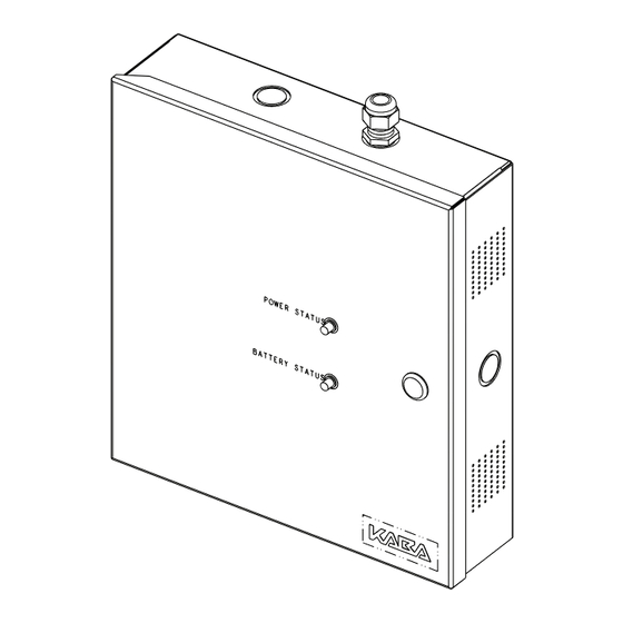
4. Relay Expansion Board Troubleshooting CAUTION The power for the MFC must be turned off before connecting or disconnecting the Relay Expansion Board. NOTE: The Relay Expansion Board relay outputs are designed to be “Fail Safe” during a power failure or IMPORTANT fire alarm: the Normally Open contact will be closed, and the Normally Closed contact will be open. - Page 14 5.0 Annex B Multi Floor Controller - MFC FRONT PANEL INDICATORS: IMPORTANT: Read manual before installation or maintenance of the unit. Green ON = Power Status OK Battery Status Green ON = Battery Status OK Power Status Tamper Power Supply...
-
Page 15: Annex C: Protection From Electromagnetic Interference
2- Connect the shield wire of the reader cable to the Ground wire 3- Crimp the shield wires and earth ground wire to the included (W) ring terminal connector. Connect the ring terminal to the mounting screw of the MFC (remove paint under the ring connector for good electrical contact.) 4- Ensure the Relay Expansion Boards (if applicable) has no more than 30VDC from elevator or other power source. - Page 16 (1 Loop) Network cable 2-4 Inches (5 to 10 cm) Cat 5 Network Cable Step 3: Connect network cable to MFC Caution: The ferrite cable clamp SHALL be installed to prevent electromagnetic interference with other equipment Multi Floor Controller...
-
Page 17: Annex E: Mfc Component Breakdown
5.0 Annex E MFC Component Breakdown Multi Floor Controller PK3661 03-19... -
Page 18: Annex F: Single Reader Wiring Diagram
5.0 Annex F Single Reader Wiring Diagram 1 2 3 1 2 3 4 1 2 3 1 2 3 4 1 2 3 4 1 2 3 4 TPR GND DOOR GND REM GND REX GND GND RX TX CGND Multi Floor Controller PK3661 03-19... -
Page 19: Annex G Dual Reader Wiring Diagram With Relay Expansion Boards
5.0 Annex G Dual Reader Wiring Diagram with Relay Expansion Boards 1 2 3 1 2 3 4 1 2 3 1 2 3 4 1 2 3 4 1 2 3 4 REM GND REX GND TPR GND DOOR GND GND RX TX CGND Multi Floor Controller PK3661... -
Page 20: Annex H: Drilling Template For Ecu Rfid Readers
5.0 Annex H Drilling Template for ECU RFID Readers Quantum RFID reader QuantumII,III, IV readers Multi Floor Controller PK3661 03-19... -
Page 21: Annex I: Fire Alarm Panel Wiring
(Not supplied by dormakaba) See Note 1 & 2 Note 1: When the MFC is connected to a Fire Alarm Panel, it must be connected to a Normally Closed (NC) dry contact output. Note 2: If the fire Alarm Connection is not used, DO Not remove the the jumper between pin 3 and 4 of J18. - Page 22 USA Inc. Customer services & support 1.800.999.6213 / + 1.248.837.3700 General information: dormakaba.us Online consumable orders: www.saflokstore.com To access all of our easy steps, please visit our support website: www.dormakabalodgingsupport.com www.dormakaba.com...
Need help?
Do you have a question about the MFC and is the answer not in the manual?
Questions and answers