Table of Contents
Advertisement
Advertisement
Table of Contents

Related Manuals for HIKVISION DS-TCG227-A Series


Summary of Contents for HIKVISION DS-TCG227-A Series
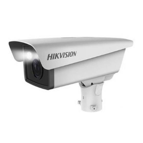
- Page 1 Entrance/Exit Capture Unit User Manual UD11822B...
- Page 2 Any and all information, including, among others, wordings, pictures, graphs are the properties of Hangzhou Hikvision Digital Technology Co., Ltd. or its subsidiaries (hereinafter referred to be “Hikvision”). This user manual (hereinafter referred to be “the Manual”) cannot be reproduced, changed, translated, or distributed, partially or wholly, by any means, without the prior written permission of Hikvision.
- Page 3 User Manual of DS-TCG227-A Series Entrance/Exit Capture Unit Regulatory information FCC information Please take attention that changes or modification not expressly approved by the party responsible for compliance could void the user’s authority to operate the equipment. FCC compliance: This equipment has been tested and found to comply with the limits for a Class A digital device, pursuant to part 15 of the FCC Rules.
- Page 4 User Manual of DS-TCG227-A Series Entrance/Exit Capture Unit Symbol Conventions The symbols that may be found in this document are defined as follows. Symbol Description Provides additional information to emphasize or supplement important points of the main text. Indicates a potentially hazardous situation, which...
- Page 5 User Manual of DS-TCG227-A Series Entrance/Exit Capture Unit Preventive and Cautionary Tips Make sure the power supply voltage is proper before using the camera. Do not drop the camera or subject it to physical shock. Do not touch sensor modules with fingers. If cleaning is necessary, use a clean cloth with a bit of ethanol and wipe it gently.
-
Page 6: Table Of Contents
User Manual of DS-TCG227-A Series Entrance/Exit Capture Unit Table of Contents CHAPTER 1 OVERVIEW........................7 ..........................7 NTRODUCTION ..........................7 EATURES CHAPTER 2 GETTING STARTED ....................... 8 ........................... 8 CTIVATION SADP S ...................... 8 CTIVATION VIA OFTWARE ........................9 CTIVATION VIA LIENT ....................... - Page 7 User Manual of DS-TCG227-A Series Entrance/Exit Capture Unit ....................49 ONFIGURE APTURE ARAMETERS 6.7.1 Configure License Plate Recognition Parameters ............49 6.7.2 Configure Flash Light Parameters ................... 50 6.7.3 Configure Vehicle Feature ....................51 ...................... 52 ONFIGURE MAGE ARAMETERS 6.8.1 Configure General Parameters ..................
-
Page 8: Chapter 1 Overview
User Manual of DS-TCG227-A Series Entrance/Exit Capture Unit Chapter 1 Overview 1.1 Introduction DS-TCG227-A series entrance/exit capture unit (hereinafter referred to as capture unit) is an all-in-one capture unit. It adopts advanced video compression technology with high compression ratio and flexible operations. -
Page 9: Chapter 2 Getting Started
User Manual of DS-TCG227-A Series Entrance/Exit Capture Unit Chapter 2 Getting Started 2.1 Activation Activate the capture unit and set login password before getting started. You can activate it via SADP software, client and web browser. STRONG PASSWORD RECOMMENDED–We highly recommend you create a... -
Page 10: Activation Via Client
User Manual of DS-TCG227-A Series Entrance/Exit Capture Unit Figure 2-1 Activate Interface(SADP) STRONG PASSWORD RECOMMENDED–We highly recommend you create a strong password of your own choosing (Using a minimum of 8 characters, including at least three of the following categories: upper case letters, lower case letters, numbers, and special characters.) in order to increase the security of your product. -
Page 11: Activation Via Web Browser
User Manual of DS-TCG227-A Series Entrance/Exit Capture Unit “The device is activated successfully” will be updated in the interface. Figure 2-2 Activate Interface(client) STRONG PASSWORD RECOMMENDED–We highly recommend you create a strong password of your own choosing (Using a minimum of 8 characters, including at least three of the following categories: upper case letters, lower case letters, numbers, and special characters.) in order to increase the security of your product. -
Page 12: Login
User Manual of DS-TCG227-A Series Entrance/Exit Capture Unit Figure 2-3 Activate Interface(Web Browser) 2. Set password, and enter password again to confirm it. 3. Click OK to finish the activation. STRONG PASSWORD RECOMMENDED–We highly recommend you create a strong password of your own choosing (Using a minimum of 8 characters, including at least three of the following categories: upper case letters, lower case letters, numbers, and special characters.) in order to increase the security of your product. -
Page 13: Logout
User Manual of DS-TCG227-A Series Entrance/Exit Capture Unit Figure 2-4 Login Interface STRONG PASSWORD RECOMMENDED–We highly recommend you create a strong password of your own choosing (Using a minimum of 8 characters, including at least three of the following categories: upper case letters, lower case letters, numbers, and special characters.) in order to increase the security of your product. -
Page 14: Adjust Image
User Manual of DS-TCG227-A Series Entrance/Exit Capture Unit scene mode for the capture unit. Steps: 1. Go to Setup Wizard > General Configuration. Figure 2-5 General Configuration 2. Configure the parameters. IP Address, Subnet Mask, Default Gateway: Configure the parameters of the captured unit. - Page 15 User Manual of DS-TCG227-A Series Entrance/Exit Capture Unit Figure 2-6 Image Adjustment Adjust Default LPR Area and Lines 1. Select the LPR area. 2. Drag the vertex to adjust the shape of the area or drag the area to adjust its position.
- Page 16 User Manual of DS-TCG227-A Series Entrance/Exit Capture Unit Figure 2-7 Redraw the LPR Area If you redraw the area, the default area will disappear. 5. Click Save to save the settings. Adjust Lens Hold or click the icons on the page to realize the following functions.
-
Page 17: Chapter 3 Live View
User Manual of DS-TCG227-A Series Entrance/Exit Capture Unit Chapter 3 Live View Purpose: The live view page allows you to view the real-time captured pictures and license plate pictures. Figure 3-1 Live View Page Refer to the table below for the description of the icons on the Live View page. -
Page 18: Configure License Plate Recognition
User Manual of DS-TCG227-A Series Entrance/Exit Capture Unit Select the arming mode. Web only supports first-level arming, second-level arming, and disarming. SDK supports first-level, second-level, third-level arming, and disarming. The first-level and second-level arming are mainly used for capture. The third-level arming only supports alarm. -
Page 19: Configure Supplement Light Parameters
User Manual of DS-TCG227-A Series Entrance/Exit Capture Unit Figure 3-2 License Plate Recognition Refer to the following table for the description of the License Plate Recognition page. No. Description Captured vehicle picture Captured license plate close-up Recognized license plate number 2. -
Page 20: Configure Image Parameters
User Manual of DS-TCG227-A Series Entrance/Exit Capture Unit For different models, the number of internal and external supplement lights is different. Please refer to the actual product. Steps: 1. Go to Live View page. 2. Click Supplement Light. 3. Select F1. -
Page 21: Configure Entrance/Exit
User Manual of DS-TCG227-A Series Entrance/Exit Capture Unit You can configure the image parameters such as brightness, contrast, shutter speed, and gain etc. of the capture unit. Steps: 1. Go to Live View page. 2. Click Image tab. 3. Configure the parameters shown in the figure below. -
Page 22: Chapter 4 Picture Search
User Manual of DS-TCG227-A Series Entrance/Exit Capture Unit Chapter 4 Picture Search The picture search function can be used normally only after the TF card is installed and works normally. The TF card supports up to 64 GB capacity. - Page 23 User Manual of DS-TCG227-A Series Entrance/Exit Capture Unit Figure 4-2 Picture Display 5. (Optional) Check a picture or several pictures and click Export Picture to export it/them to the saving path you have configured.
-
Page 24: Chapter 5 Log Search
User Manual of DS-TCG227-A Series Entrance/Exit Capture Unit Chapter 5 Log Search You can search, view, and save the log information normally only after the TF card is installed and works normally. Purpose: You can search, view, and save the log information saved in the TF card. -
Page 25: Chapter 6 Capture Unit Configuration
User Manual of DS-TCG227-A Series Entrance/Exit Capture Unit Chapter 6 Capture Unit Configuration 6.1 View Device Status Purpose: You can view the device IP address and device status such as the live view IP address, frame rate, stream time, etc. - Page 26 User Manual of DS-TCG227-A Series Entrance/Exit Capture Unit Figure 6-2 Local Configuration 2. Configure the following parameters. Live View Parameters: Set the protocol type, live view performance, and rules. Protocol Type: TCP and UDP are selectable. TCP: Ensures complete delivery of streaming data and better video quality, yet the real-time transmission will be affected.
-
Page 27: Device Configuration
User Manual of DS-TCG227-A Series Entrance/Exit Capture Unit Save snapshots in live view to: Set the saving path of the manually captured pictures in live view mode. Save downloaded picture to: Set the saving path for the downloaded picture. - Page 28 User Manual of DS-TCG227-A Series Entrance/Exit Capture Unit After restoring the default settings, the IP address is also restored to the default IP address, please be careful for this action. 6.3.1.3 Export Debug File Steps: 1. Go to Configuration > Device Configuration > System Maintenance > Export Debug File.
-
Page 29: System Configuration
User Manual of DS-TCG227-A Series Entrance/Exit Capture Unit Figure 6-7 Export Configuration File 2. Click Export and set the saving path to save the configuration file in local storage. 6.3.1.6 Upgrade the System Steps: 1. Go to Configuration > Device Configuration > System Maintenance > Import Configuration File. - Page 30 User Manual of DS-TCG227-A Series Entrance/Exit Capture Unit Figure 6-9 Device Information 2. View the device information. 6.3.2.2 Configure Serial Ports Purpose: When the RS-485 signal of the vehicle detector is connected to the capture unit, you need to configure the RS-485 parameters. Only when the RS-485 parameters of the capture unit are consistent with that of the sending device, they can communicate normally.
- Page 31 User Manual of DS-TCG227-A Series Entrance/Exit Capture Unit Figure 6-10 Serial Port Configuration 2. Configure the RS-485 parameters including the Baud Rate, Data Bit, Stop Bit, Parity, Flow Control, and Working Mode. The default working mode for RS-485 is LED Display. The Application Trigger Mode is used for capture.
- Page 32 User Manual of DS-TCG227-A Series Entrance/Exit Capture Unit Figure 6-11 TCP/IP Configuration 2. Configure the basic network settings, including the NIC Type, IPv4 or IPv6 Address, IPv4 or IPv6 Subnet Mask, IPv4 or IPv6 Default Gateway, MTU settings, Multicast Address, ANPR IP settings, Alarm settings, and etc.
- Page 33 User Manual of DS-TCG227-A Series Entrance/Exit Capture Unit Figure 6-12 Port Settings 2. Set the HTTP port, RTSP port, and SDK port of the capture unit. HTTP Port: The default port number is 80, and it can be changed to any port No.
- Page 34 User Manual of DS-TCG227-A Series Entrance/Exit Capture Unit Figure 6-13 HTTPS Configuration 2. Create the self-signed certificate or authorized certificate. OPTION 1: Create the self-signed certificate 1) Click the Create button to create the following dialog box. 2) Enter the country, host name/IP, validity and other information.
- Page 35 User Manual of DS-TCG227-A Series Entrance/Exit Capture Unit 3. Synchronize time. Synchronizing Time by NTP Server (1) Check NTP to enable the function. (2) Configure the following parameters: Server Address: IP address of NTP server. NTP Port: Port of NTP server.
- Page 36 User Manual of DS-TCG227-A Series Entrance/Exit Capture Unit 5. Click Save to save the settings. 6.3.2.7 Configure Service Purpose: You can enable user lock. Then if the admin logs in to the capture unit incorrectly for 7 times continuously, the admin will be locked for 30 minutes. If the operator logs in to the capture unit incorrectly for 5 times continuously, the operator will be locked for 30 minutes.
-
Page 37: Configure Encoding And Storage
User Manual of DS-TCG227-A Series Entrance/Exit Capture Unit 3. Click Save to save the settings. 6.4 Configure Encoding and Storage 6.4.1 Configure Video Encoding Purpose: You can configure the stream parameters of the capture unit, including the main stream, sub-stream, and third stream. -
Page 38: Configure Image Encoding
User Manual of DS-TCG227-A Series Entrance/Exit Capture Unit Figure 6-21 Third Stream Configuration 2. Select the Stream Type. Video and Video & Audio are selectable. 3. Customize the following parameters. Max. Bitrate: Set the max. bitrate to 32~16384 Kbps. The higher value corresponds to the higher video quality, but the higher bandwidth is required. -
Page 39: Configure Roi
User Manual of DS-TCG227-A Series Entrance/Exit Capture Unit Figure 6-22 Image Encoding Configuration 2. Select the Capture Resolution. 3. Enter the JPEG Picture Size. It ranges from 64 to 8196 KB. 4. Click Save to save the settings. The capture resolution and picture size are target value. When the image encoding reaches the limit, the actual value may be larger than the target value. -
Page 40: Configure Record Schedule
User Manual of DS-TCG227-A Series Entrance/Exit Capture Unit Figure 6-23 Region of Interest Settings 1. Check Enable under Fixed Area item. 2. Select the Stream Type for ROI encoding. Each stream type only supports one ROI. 3. Select the Area Code from the drop-down list for ROI settings. There are four fixed areas selectable. - Page 41 User Manual of DS-TCG227-A Series Entrance/Exit Capture Unit record files of scheduled recording are stored in the TF card. Steps: 1. Go to Configuration > Device Configuration > Encoding and Storage > Record Schedule. Figure 6-24 Record Schedule Configuration 2. (Optional) Check Enable Recording Overwriting.
-
Page 42: Configure Redundant Storage
User Manual of DS-TCG227-A Series Entrance/Exit Capture Unit If you want to record in different time sections, check the Customize checkbox. Set the Start Time and End Time. The time of each segment cannot be overlapped. Up to 4 segments can be configured. -
Page 43: Configure Ftp
User Manual of DS-TCG227-A Series Entrance/Exit Capture Unit 2) Enter the Video Quota Ratio. The Capture Quota Ratio ranges from 0 to 100%. The sum of Capture Quota Ratio and Video Quota Ratio should be 100%. 6.4.6 Configure FTP... - Page 44 User Manual of DS-TCG227-A Series Entrance/Exit Capture Unit selectable. 4) Select the content in different directories. For the Parent Directory, you can select Device Name, Device No., and Device IP Address. For the Level 2/3/4 Directory, you can select Camera Name, Camera No., Device IP Address, etc.
-
Page 45: Configure Text Overlay
User Manual of DS-TCG227-A Series Entrance/Exit Capture Unit 1) Select the Separator. 2) Select the Elements of each name. Figure 6-30 Name Rule Configuration 5. Configure the OSD Information. Figure 6-31 OSD Information 6. Click Save to save the settings. - Page 46 User Manual of DS-TCG227-A Series Entrance/Exit Capture Unit Figure 6-32 Single Picture Overlay 2. Check Capture Picture Overlay. 3. Configure the parameters below. Percentage: the percentage of the information overlaid on the picture. Font Size: the font size of the overlay information.
-
Page 47: Configure Video Osd
User Manual of DS-TCG227-A Series Entrance/Exit Capture Unit Figure 6-33 Overlay Information List 1) Check the overlay information or check Select All to display all the overlay information. 2) Configure the overlay information. Type: You can edit the overlay information type. -
Page 48: Configure Application Mode
User Manual of DS-TCG227-A Series Entrance/Exit Capture Unit Steps: 1. Go to Configuration > Device Configuration > Text Overlay > Video. Figure 6-34 Video OSD Settings 2. Select the OSD Properties. 3. Select the OSD Font Size. 4. Configure the parameters below according to your needs. - Page 49 User Manual of DS-TCG227-A Series Entrance/Exit Capture Unit Figure 6-35 Application Mode 2. Select the Trigger Type. Vehicle Detection 1) Select the Picture Mode. Scene Picture and Scene Picture + Close-up Picture are selectable. 2) (Optional) Check Capture Plate Absence Vehicle. Then the vehicle without license plate will be captured.
-
Page 50: Configure Capture Parameters
User Manual of DS-TCG227-A Series Entrance/Exit Capture Unit configured according to the actual conditions. RS-485 1) Select the Picture Mode. Scene Picture and Scene Picture + Close-up Picture are selectable. 2) Select the Scene Mode. Entrance and Exit, Toll Station, and Entrance and Exit of Underground Parking Lot are selectable. -
Page 51: Configure Flash Light Parameters
User Manual of DS-TCG227-A Series Entrance/Exit Capture Unit Steps: 1. Go to Configuration > Device Configuration > Capture Parameters > LPR Parameters. Figure 6-37 LPR Parameters 2. Select the License Plate Type. Small-Size Plate Recognition and Large-Size Plate Recognition are selectable. -
Page 52: Configure Vehicle Feature
User Manual of DS-TCG227-A Series Entrance/Exit Capture Unit Figure 6-38 Flash Light Parameters 2. Click IO:1 to control constant light. Control Constant Light by Brightness 1) Check Control Constant Light by Brightness. 2) Drag the slider to adjust the Brightness Threshold. -
Page 53: Configure Image Parameters
User Manual of DS-TCG227-A Series Entrance/Exit Capture Unit Feature. Figure 6-39 Vehicle Feature 2. Check Vehicle Color Recognition or Enable Car Logo Recognition to enable the function. 3. Click Save to save the settings. 6.8 Configure Image Parameters 6.8.1 Configure General Parameters... - Page 54 User Manual of DS-TCG227-A Series Entrance/Exit Capture Unit Saturation: It describes the colorfulness of the image color, which ranges from 1 to 100, and the default value is 50. Sharpness: It describes the edge contrast of the image, which ranges from 1 to 100, and the default value is 50.
-
Page 55: Configure Video Parameters
User Manual of DS-TCG227-A Series Entrance/Exit Capture Unit Sensitivity. Enable Gamma Correction: Check the function and adjust the Gamma Correction. The higher the value is, the stronger the correction strength is. 3. (Optional) Click Capture Test to test the effect. -
Page 56: Configure Picture Parameters
User Manual of DS-TCG227-A Series Entrance/Exit Capture Unit Figure 6-46 Normal Mode If the 3D DNR level is too high, the image may become fuzzy. Expert Mode: Adjust the Spatial Intensity and Time Intensity. Figure 6-47 Expert Mode If the special intensity is too high, the outline of the image may become fuzzy and the details may lose. -
Page 57: Configure Icr
User Manual of DS-TCG227-A Series Entrance/Exit Capture Unit Figure 6-50 Picture Parameters 2. Click Capture Test, and full-screen monitoring will pop out. You can click Open Folder to choose the file. 3. (Optional)Check Enable Plate Enhancing, you can choose Plate Lighting Level ranged from 0 to 100. -
Page 58: Configure Entrances And Exits
User Manual of DS-TCG227-A Series Entrance/Exit Capture Unit Scheduled Switch: Configure the Day/Night Mode, Start Time, and End Time. Figure 6-53 ICR Mode- Scheduled Switch 3. Click Save to save the settings. 6.9 Configure Entrances and Exits 6.9.1 Configure Entrance and Exit... -
Page 59: Configure Whitelist And Blacklist
User Manual of DS-TCG227-A Series Entrance/Exit Capture Unit 2. Select the Control Mode. By Camera and By Platform are selectable. If you select By Platform, you need to configure the rules in Vehicle Information Management. 3. Select to enable or disable keeping barrier open for following vehicle. - Page 60 User Manual of DS-TCG227-A Series Entrance/Exit Capture Unit Figure 6-55 Whitelist and Blacklist Configuration 2. Import whitelist and blacklist to the capture unit. 1) Click Import and the window pops up as below. Figure 6-56 Import Whitelist and Blacklist 2) Click Download Template to download the list template as below.
- Page 61 User Manual of DS-TCG227-A Series Entrance/Exit Capture Unit Figure 6-58 Import Completed 6) Click Exit to return to the Whitelist and Blacklist Configuration page, and you can view the imported vehicle information. Figure 6-59 Imported Vehicle Information 3. Add whitelist or blacklist vehicle information to the capture unit.
-
Page 62: Configure Display
User Manual of DS-TCG227-A Series Entrance/Exit Capture Unit Figure 6-61 Edit Whitelist/Blacklist Vehicle Information 2) Edit the information. 3) Click OK to save the settings. 5. Search the whitelist/blacklist vehicle information. 1) Configure the search condition and keywords. License Plate No.: Enter the complete license plate number in the Keywords text field. - Page 63 User Manual of DS-TCG227-A Series Entrance/Exit Capture Unit The LED display function can only take effect when adopting the Hikvision IS-TVL224-4-5EY series LED display. Steps: 1. Go to Configuration > Device Configuration > Entrances and Exits > Display. Figure 6-64 LED Display Configuration 2.
-
Page 64: User Management
User Manual of DS-TCG227-A Series Entrance/Exit Capture Unit 6.10 User Management Go to Configuration > Device Configuration > User Management. Figure 6-65 User Management Adding a User Account Steps: 1. Click Add to add a user account. Figure 6-66 Add a User 2. - Page 65 User Manual of DS-TCG227-A Series Entrance/Exit Capture Unit your product. Editing a User Account Steps: 1. Select a user. 2. Click Edit to edit the user parameters. Figure 6-67 Edit the Admin Figure 6-68 Edit the Operator 3. Click OK to save the settings.
- Page 66 User Manual of DS-TCG227-A Series Entrance/Exit Capture Unit 1. Select the user you want to delete and click Delete. 2. Click OK on the pop-up dialogue box to delete the user. You cannot delete the admin account. 0402311080917...
- Page 67 User Manual of DS-TCG227-A Series Entrance/Exit Capture Unit...
Need help?
Do you have a question about the DS-TCG227-A Series and is the answer not in the manual?
Questions and answers