
Subscribe to Our Youtube Channel
Related Manuals for Omron R88L-EA-AF


Summary of Contents for Omron R88L-EA-AF
- Page 1 Servo Systems Accurax Linear Axis Installation Manual R88L-EA-AF ENGLISH / DEUTSCH I162E-EN-01...
- Page 2 OMRON. No patent liability is assumed with respect to the use of the information contained herein. Moreover, because OMRON is constantly striving to improve its high-quality products, the information contained in this manual is subject to change without notice.
-
Page 3: Table Of Contents
CONTENTS CONTENTS Section 1 ENGLISH Introduction ........................... 1-2 Transportation / Handling / Storage ..................1-4 Design and Customer Drawings ..................1-8 Electrical Setup ........................1-18 System Configuration ......................1-22 System Integration ......................1-23 Maintenance ........................1-32 Repair and Modifications ....................1-37 Section 2 DEUTSCH Einleitung .......................... - Page 4 CONTENTS Accurax Linear Axis Installation Manual...
- Page 5 ENGLISH 1-1 Introduction ..........1-2 1-1-1 Notice .
-
Page 6: Introduction
Notice This manual is part of the scope of delivery of your R88L-EA-AF linear axis. OMRON EUROPE B.V. products are manufactured for use according to proper procedures by a qualified operator and only for the purposes described in this manual. - Page 7 1 ENGLISH Emergency stop circuits or devices, interlock circuits or devices and similar safety measures must be provided by the customer as external circuits or devices. Failure to do so may result in serious accidents. Do not attempt to disassemble, repair, or modify any linear systems. Any attempt to do so may result in malfunction, electrical shock, fire or reduced product lifetime.
-
Page 8: Transportation / Handling / Storage
• Make sure to read and understand all stickers been attached outside of the wooden shipping box or been placed inside • If for any reason, the linear system needs to be shipped back to OMRON EUROPE B.V. or being shipped to some other place, make sure to always and exclusively use original shipping box provided by OMRON EUROPE B.V. -
Page 9: Handling
1 ENGLISH 1-2-3 Handling Remove the system from its shipping box carefully. If you use cutting tools, you could scratch the outer surface of the linear slider or even damage cables. The cover of the wooden transportation box is fastened to the box itself using wood screws. All screws are indi- cated by black arrow labels as shown below. - Page 10 1 ENGLISH Please, follow the next steps: • Remove the cover of the slider. Remove the three M3 screws on each side from each front plate on the left and right hand side of the slider. • Sliders with a very short stroke, it may be necessary to also disassemble the mounting plate before you are able to remove the cover.
-
Page 11: Storage
1 ENGLISH 1-2-4 Storage Make sure to prevent accidents and injuries using the following preventive measures before storing the linear system: • Mark the specific storage area as magnetically dangerous environment • Keep the storage area clean from any ferromagnetic objects, especially tools or screws •... -
Page 12: Design And Customer Drawings
1-3-2 Product Tag In case of repair or any other issues or problems with the linear axis it is important to contact your local OMRON representative with the parameters of the product on hand. For this purpose you will find a product identification label on the far left hand end of the base profile as seen from in front of the linear axis with the cable chain between you and the axis. -
Page 13: Acceleration / Payload Diagrams
1 ENGLISH 1-3-3 Acceleration / Payload Diagrams All acceleration/payload diagrams represent theoretical performance values and are evaluated based on peak and constant forces combined with a specific payload reasonable for each particular slider size. (m/s²) R88L-EA-AF-0303- (m/s²) R88L-EA-AF-0306- 30.0 45.0 40.0 25.0... -
Page 14: Part Names
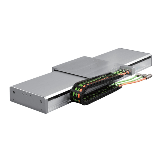
1 ENGLISH 1-3-4 Part Names Mounting plate End plate Cover Recirculating ball bearings Measurement Magnet track tape Connector box End plate Cable chain with cables 1 - 10 Accurax Linear Axis Installation Manual... -
Page 15: Design Overview
1 ENGLISH 1-3-5 Design Overview R88L-EC-AF-0303 Number Stroke of screws 1080 1176 1070 1272 1166 1368 1262 1464 1358 1560 1454 1656 1550 1752 1646 1848 1742 1944 1838 2040 1934 2136 2030 2232 2126 2328 1 - 11 Accurax Linear Axis Installation Manual... - Page 16 1 ENGLISH R88L-EC-AF-0306 Number Stroke of screws 1080 1176 1022 1272 1118 1368 1214 1464 1310 1560 1406 1656 1502 1752 1598 1848 1694 1944 1790 2040 1886 2136 1982 2232 2078 2328 1 - 12 Accurax Linear Axis Installation Manual...
- Page 17 1 ENGLISH R88L-EC-AF-0606 Number Stroke of screws 1032 1128 1224 1070 1320 1166 1416 1262 1512 1358 1608 1454 1704 1550 1800 1646 1896 1742 1992 1838 2088 1934 2184 2030 2280 2126 2376 1 - 13 Accurax Linear Axis Installation Manual...
- Page 18 1 ENGLISH R88L-EC-AF-0609 Number Stroke of screws 1032 1128 1224 1022 1320 1118 1416 1214 1512 1310 1608 1406 1704 1502 1800 1598 1896 1694 1992 1790 2088 1886 2184 1982 2280 2078 2376 1 - 14 Accurax Linear Axis Installation Manual...
- Page 19 1 ENGLISH R88L-EC-AF-0612 Number Stroke of screws 1032 1128 1224 1320 1070 1416 1166 1512 1262 1608 1358 1704 1454 1800 1550 1896 1646 1992 1742 2088 1838 2184 1934 2280 2030 2376 1 - 15 Accurax Linear Axis Installation Manual...
- Page 20 1 ENGLISH R88L-EC-AF-1112 Number Stroke of screws 1032 1128 1224 1320 1070 1416 1166 1512 1262 1608 1358 1704 1454 1800 1550 1896 1646 1992 1742 2088 1838 2184 1934 2280 2030 2376 2126 2442 1 - 16 Accurax Linear Axis Installation Manual...
- Page 21 1 ENGLISH R88L-EC-AF-1115 Number Stroke of screws 1032 1128 1224 1320 1022 1416 1118 1512 1214 1608 1310 1704 1406 1800 1502 1896 1598 1992 1694 2088 1790 2184 1886 2280 1982 2376 2078 2472 1 - 17 Accurax Linear Axis Installation Manual...
-
Page 22: Electrical Setup
1-4-1 Encoder Options You can select several different brands and types of amplifier in order to operate your OMRON EUROPE B.V. lin- ear motor axis. The accuracy and environmental requirements also differ from application to application. To satisfy all of these aspects you can currently select among 5 different encoder options. A list of the relevant options, cate-... -
Page 23: Wiring
1 ENGLISH 1-4-2 Wiring R88L-EA-AF-@@@@-@@@@ R88L-EA-AF-@@@@-@@@@-0003 Encoder cable Pin No. Signal 15-pin D-Sub connector SDA* SCL* Not used /Ref Uo- /Cos U2- /Sin U1- Not used Not used Not used Ref Uo Cos U2 Sin U1 Inner shield Housing Outer shield... - Page 24 1 ENGLISH R88L-EA-AF-@@@@-@@@@-0001 R88L-EA-AF-@@@@-@@@@-0002 R88L-EA-AF-@@@@-@@@@-0004 Encoder cable 15-pin D-Sub connector Pin No. Signal SDA* SCL* Not used /Ref Uo- /Cos U2- /Sin U1- Not used Not used Not used Ref Uo Cos U2 Sin U1 Inner shield Housing Outer shield Power cable Pin No.
- Page 25 1 ENGLISH R88L-EA-AF-@@@@-@@@@-0005 Encoder cable 15-pin D-Sub connector Pin No. Signal SDA* SCL* Not used Not used Not used Not used Not used Not used Not used Not used Not used Not used Inner shield Housing Outer shield Power cable LRRA06AMRPN182 connector (pins) Pin No.
-
Page 26: System Configuration
1 ENGLISH System Configuration Accurax G5 servo drive EtherCAT and Analog/pulse models Power cable Serial converter cable Serial converter unit (optional) Linear encoder cable extension Power (optional) Linear encoder Hall & temperature sensors Hall & extension cable (optional) temperature sensors Accurax linear motor axis Model R88A-CRKNxCR-E... -
Page 27: System Integration
1 ENGLISH System Integration Before or during installation of the R88L-EA-AF linear system, please make sure to read and understand the fol- lowing guideline: • Always be aware that the linear system includes powerful magnets. • Make sure that only trained staff enters the working area. -
Page 28: Alignment
The cables may be crossed, but should not be routed or laid closely together in a parallel orientation. 1-6-4 Ambient Working Conditions In order to meet accuracy and lifetime requirements, you must always operate the R88L-EA-AF linear axis within the following ambient operation conditions: Item... -
Page 29: Installing The Linear Axis In The System
1 ENGLISH 1-6-5 Installing the Linear Axis in the System Each linear axis is shipped in a wooden box. To prevent the product from being damaged during shipping, the product is locked. “Locked” means that the slider is clamped to one of the end plates by means of a red screw. For the mounting process it is necessary to tighten all the mounting screws to the specified torque in order to ensure accuracy and a long lifetime of the product. - Page 30 1 ENGLISH In order to mount the axis into your machine, please remove the mounting plate. • R88L-EA-AF-03: 6 screws M4x14 • R88L-EA-AF-06: 8 screws M5x20 • R88L-EA-AF-11: 8 screws M6x20 Remove the mounting plate. The mounting plate is held in position by two pins. Make sure not to tilt the plate during removal.
- Page 31 1 ENGLISH The next step requires removing the axis cover. For this purpose, please remove the three M3x12 screws that fas- ten the cover to each front plate. The cover may be under slight tension. Loosen the screws crosswise one after the other. Now, please remove the cover.
- Page 32 1 ENGLISH This is how your linear axis should look immediately before installing it in the machinery. Remove all covers from the magnet plates. Magnet track covers can have sharp edges. The moving carriage cannot be moved if you do not remove the covers. Insert M6x35 screws into all empty screw positions.
- Page 33 1 ENGLISH The next steps will show you how to reassemble the linear axis. Fit the cover. Use three M3x12 screws on each side to securely fasten the cover to both front plates of the linear motor axis. Always observe the torque specified in Section 1-6-1 Mechanical Integration. Please use a torque wrench.
- Page 34 Make sure to bring the pins and pin holes into correct alignment. Fasten the mounting plate to the carriage. Use the following screws for this purpose: • R88L-EA-AF-03: 6 screws M4x14 • R88L-EA-AF-06: 8 screws M5x20 • R88L-EA-AF-11: 8 screws M6x20 Always observe the torque specified in Section 1-6-1 Mechanical Integration.
- Page 35 1 ENGLISH Assemble both limit switches EE-SX913-P-R with one M3x08 screw each. Both limit switch carriers are moveable along the stroke and can also be fastened with two M3x08 screws. The cam switch is attached to the carriage with two M3x06 screws. DONE! 1 - 31 Accurax Linear Axis Installation Manual...
-
Page 36: Maintenance
As a lubrication accessory, we recommend using the original THK accessory. As a lubrication tool, please use an MG70 from THK. All OMRON linear motor axis run with THK AFB-LF grease. If you received a special linear system that may run on special grease according your requirements, please contact your local OMRON EUROPE B.V. representative. - Page 37 1 ENGLISH One possibility is to access the linear blocks via the two lubrication holes in each of the end plates. Another possible way to access the axis and lubricate the recirculating ball bearing blocks is to use the gap between the cover and the base plate.
-
Page 38: Measurement Scale
1 ENGLISH 1-7-2 Measurement Scale Wipe down the measurement tape with a dry piece of lint-free cloth every 6 months. Make sure to wipe down the total stroke length of the axis. Make sure the cloth is new and clean does not have any metal chips or any other particles attached that could irreparably damage the measurement tape. -
Page 39: Cables
The top section of the cable chain will be approx. half way above the lower section of the chain. Fasten the upper part of the cable using cables ties. OMRON recommends to use two cable ties for each cable at each end of the cable chain. - Page 40 Return the cable to the center position between 1 and 2 and fasten the cable there using cable ties. OMRON rec- ommends using two cable ties for each cable at each end of the cable chain. cable does...
-
Page 41: Repair And Modifications
Condition precedent to perform independently repair and maintenance is an official training performed by OMRON EUROPE B.V. During warranty it is mandatory to report every repair action performed by the customer to OMRON EUROPE B.V. or to an authorized distributor. - Page 42 1,694 mm to 2,126 mm stroke: cable length 1.8 m R88L-EP-CB-0010-0018, R88L-EP-CB-0021-0018, R88L-EP-CB-0030-0018 For any questions regarding your linear motor axis options or the encoder system used inside, please contact your local OMRON EUROPE B.V. representative. 1 - 38 Accurax Linear Axis Installation Manual...
-
Page 43: Deutsch
DEUTSCH 2-1 Einleitung ........... . 2-2 2-1-1 Allgemeine Hinweise . -
Page 44: Einleitung
Umweltschutzbedingungen erfüllen, die im jeweiligen Installationsland in Kraft sind. Bitte setzen Sie sich ggf mit Ihrem OMRON EUROPE B.V. Repräsentanten oder anderen autorisierten Distributo- ren in Verbindung falls Ihnen zum sicheren Betrieb Ihrer Linearmotorachse Informationen und / oder Sicherheits- hinweisen fehlen oder unklar sind. - Page 45 2 DEUTSCH Bewegliche Teile der Linearmotorachse können Hände, Finger oder andere externe Gliedmaßen quetschen oder sogar brechen. Magnetische Komponenten müssen vorsichtig gehandhabt werden und müssen von anderen metallischen Gegenständen ferngehalten werden Dies gilt vor allem für die Permanentmagnetbahn. Berühren Sie nicht die Linearmotorachse oder schrauben diese auseinander während die elektrische Stromversorgung nicht unterbrochen ist, oder die Linearmotorachse in Bewegung ist.
-
Page 46: Transport / Umschlag / Lagerung
• Lesen und verstehen Sie alle Beschriftungen, Markierung und Aufkleber, die sich auf der Außenseite der Holzki- ste oder innerhalb befinden • Falls die Linearmotorachse zur Reparatur oder andere Zwecke zurück zu OMRON EUROPE B.V. oder an andere Destinationen geschickt werden muss, sollte dafür immer die originale Holzverpackungskiste verwendet werden, die durch OMRON EUROPE B.V. -
Page 47: Umschlag / Handhabung Auspacken
2 DEUTSCH 2-2-3 Umschlag / Handhabung Auspacken Bitte stellen Sie sicher die Holztransportkiste vorsichtig zu öffnen. Bei der Verwendung von Schnittwerkzeugen könnten elektrischen Kabel beschädigt oder die Oberfläche der Achse zerkratzt werden. Der Deckel der Holzkiste ist mit Holz-schrauben mit der Holzkiste verbunden. Die Positionen sind mit Hinweissym- bolen ge-kennzeichnet. - Page 48 2 DEUTSCH Gehen Sie dazu wir folgt vor: • Entfernen Sie die Abdeckung der Achse. Dazu müssen Sie auf jeder Seite jeweils drei Schrauben M3 aus der Stirnplatte links und rechts lösen. • Bei sehr kurzen Achsen, kann es sein, dass Sie zusätzlich die Montageplatte von dem Schlitten lösen müssen um die Abdeckung von der Achse zu demontieren.
-
Page 49: Lagerung
2 DEUTSCH 2-2-4 Lagerung Befolgen Sie die folgenden Anweisungen und Vorsichts-maßnahmen bevor Sie das Achssystem für längere Zeit an einem bestimmten Ort lagern: • Kennzeichnen Sie die spätere Lagerstätte, so dass andere Mitarbeiter erkennen, dass gefährliche Permanentmagnete in den zu lagernden Produkten verbaut sind •... -
Page 50: Design Und Kundenzeichnungen
Design und Kundenzeichnungen 2-3-1 Überblick OMRON EUROPE B.V.’s R88L-EA-AF Linearmotorachse besteht aus 3 Familien mit insgesamt 7 verschiedenen Linearmotorachstypen. Jede dieser Type kann mit Arbeitshüben zwischen 110 mm und 2126 mm bestellt werden. Die folgende Tabelle zeigt dies in einer Übersicht:... -
Page 51: Beschleunigung / Nutzlast Kurven
2 DEUTSCH 2-3-3 Beschleunigung / Nutzlast Kurven ADie abgebildeten Beschleunigungs/Nutzlast-Kurven stellen die theoretische Spitzen- und Dauerlastbeschleuni- gung bei entsprechender Nutzlast dar, die der Achsgröße angepasst ist. (m/s²) R88L-EA-AF-0303- (m/s²) R88L-EA-AF-0306- 30.0 45.0 40.0 25.0 35.0 20.0 30.0 25.0 15.0 20.0... -
Page 52: Explosionsansicht
2 DEUTSCH 2-3-4 Explosionsansicht Montageplatte Stirnplatte Deckel Führungswagen Magnetbahn Maßband Steckerbox Stirnplatte Kabelkette mit Kabeln 2 - 10 Accurax Linear Axis Installation Manual... -
Page 53: Design Überblick
2 DEUTSCH 2-3-5 Design Überblick R88L-EC-AF-0303 Schrauben anzahl 1080 1176 1070 1272 1166 1368 1262 1464 1358 1560 1454 1656 1550 1752 1646 1848 1742 1944 1838 2040 1934 2136 2030 2232 2126 2328 2 - 11 Accurax Linear Axis Installation Manual... - Page 54 2 DEUTSCH R88L-EC-AF-0306 Schrauben anzahl 1080 1176 1022 1272 1118 1368 1214 1464 1310 1560 1406 1656 1502 1752 1598 1848 1694 1944 1790 2040 1886 2136 1982 2232 2078 2328 2 - 12 Accurax Linear Axis Installation Manual...
- Page 55 2 DEUTSCH R88L-EC-AF-0606 Schrauben anzahl 1032 1128 1224 1070 1320 1166 1416 1262 1512 1358 1608 1454 1704 1550 1800 1646 1896 1742 1992 1838 2088 1934 2184 2030 2280 2126 2376 2 - 13 Accurax Linear Axis Installation Manual...
- Page 56 2 DEUTSCH R88L-EC-AF-0609 Schrauben anzahl 1032 1128 1224 1022 1320 1118 1416 1214 1512 1310 1608 1406 1704 1502 1800 1598 1896 1694 1992 1790 2088 1886 2184 1982 2280 2078 2376 2 - 14 Accurax Linear Axis Installation Manual...
- Page 57 2 DEUTSCH R88L-EC-AF-0612 Schrauben anzahl 1032 1128 1224 1320 1070 1416 1166 1512 1262 1608 1358 1704 1454 1800 1550 1896 1646 1992 1742 2088 1838 2184 1934 2280 2030 2376 2 - 15 Accurax Linear Axis Installation Manual...
- Page 58 2 DEUTSCH R88L-EC-AF-1112 Schrauben anzahl 1032 1128 1224 1320 1070 1416 1166 1512 1262 1608 1358 1704 1454 1800 1550 1896 1646 1992 1742 2088 1838 2184 1934 2280 2030 2376 2126 2442 2 - 16 Accurax Linear Axis Installation Manual...
- Page 59 2 DEUTSCH R88L-EC-AF-1115 Schrauben anzahl 1032 1128 1224 1320 1022 1416 1118 1512 1214 1608 1310 1704 1406 1800 1502 1896 1598 1992 1694 2088 1790 2184 1886 2280 1982 2376 2078 2472 2 - 17 Accurax Linear Axis Installation Manual...
-
Page 60: Elektrischer Anschluss
Ihren OMRON EUROPE B.V. Außendienst. Nehmen Sie auf keinen Fall die Linearachse in Betrieb ohne zuvor die richtigen Anschlussschemen und Belegungen nachvollzogen und verstanden zu haben. Für etwaige Schäden aus unsachgemäßer Verdrahtung kann OMRON EUROPE B.V. keine Haftung übernehmen. 2-4-1 Encoderoptionen Auf Grund der Vielzahl von möglichen, anschließbaren Leistungstreibern in Verbindung mit verschiedensten... -
Page 61: Anschlussbelegung
2 DEUTSCH 2-4-2 Anschlussbelegung R88L-EA-AF-@@@@-@@@@ R88L-EA-AF-@@@@-@@@@-0003 Encoderkabel Pin Nr. Signal Stecker D-Sub 15polig (Stifte) SDA* SCL* Nicht belegt /Ref Uo- /Cos U2- /Sin U1- Nicht belegt Nicht belegt Nicht belegt Ref Uo Cos U2 Sin U1 innerer Schirm Gehäuse äußerer Schirm... - Page 62 2 DEUTSCH R88L-EA-AF-@@@@-@@@@-0001 R88L-EA-AF-@@@@-@@@@-0002 R88L-EA-AF-@@@@-@@@@-0004 Encoderkabel Stecker D-Sub 15polig (Stifte) Pin Nr. Signal SDA* SCL* Nicht belegt /Ref Uo- /Cos U2- /Sin U1- Nicht belegt Nicht belegt Nicht belegt Ref Uo Cos U2 Sin U1 innerer Schirm Gehäuse äußerer Schirm Leistungskabel Pin Nr.
- Page 63 2 DEUTSCH R88L-EA-AF-@@@@-@@@@-0005 Encoderkabel Pin Nr. Signal Stecker D-Sub 15polig (Stifte) SDA* SCL* Nicht belegt Nicht belegt Nicht belegt Nicht belegt Nicht belegt Nicht belegt Nicht belegt Nicht belegt Nicht belegt Nicht belegt innerer Schirm Gehäuse äußerer Schirm Leistungskabel Stecker LRRA06AMRPN182 (Stifte) Pin Nr.
-
Page 64: Systemkonfiguration
2 DEUTSCH Systemkonfiguration Accurax G5-servoantrieb EtherCAT-und Analog/Impuls Spannungsversorgungskabel Seriell-Wandlerkabel Serieller Wandler (optional) Linearencoder-Kabelverlängerung Spannungsversorgung (optional) Linearencoder Hall- und Hall- und Temperatursensor-Verlängerungskabel Temperatur- (optional) sensoren Accurax-Linearmotorachse Modell R88A-CRKNxCR-E R88A-CAWxxS-DE R88A-SC01K-E R88A-CFKAxCR-E R88A-CFKBxCR-E none @-0001 @-0002 @-0003 @-0004 @-0005 2 - 22 Accurax Linear Axis Installation Manual... -
Page 65: Systemintegration
2 DEUTSCH Systemintegration Stellen Sie sicher die folgenden Hinweise zur Integration der R88L-EA-AF Linearmotorachse für in Ihre Maschine sorgfältig zu lesen und verstanden zu haben: • Seien Sie sich immer bewusst, dass die Linearmotorachse starke Permanentmagnete beinhaltet. • Stellen Sie sicher, dass sich nur geschultes Personal in der Nähe der Linearmotorachse aufhält oder diese handhabt. -
Page 66: Ausrichtung Der Achse
2 DEUTSCH Das vorzeitige Lösen der Transportsicherung kann zu gequetschten oder gebrochenen Fingern, Händen oder anderen Extremitäten führen, die mit der Achse in Berührung kommen. Schließen Sie während der Montage der Linearmotorachse in Ihre Maschinen auf keinen Fall die Kabel an. Sorgen Sie dafür, dass alle Kabel leistungsfrei sind. •... -
Page 67: Elektrische Informationen
Die Kabel können überkreuzt werden jedoch sollten sie nicht dicht zusammen parallel zu einander zu geführt oder verlegt werden. 2-6-4 Arbeitsumgebung Um die gewünschte Genauigkeit und Lebensdauer zu erreichen, vergewissern Sie sich bitte, dass Ihre R88L-EA-AF Linearmotorachse nur unten den nachfolgend beschriebenen Umgebungsbedingungen in Betrieb geht: Umgebungseigenschaft Wert Temperatur 22ºC, ±2ºC... -
Page 68: Montage Der Linearmotorachse
2-6-5 Montage der Linearmotorachse Jede OMRON EUROPE B.V. Linearmotorachse wird in einer Holzkiste transportiert und versandt. Um zu vermei- den, dass die Achse in dieser Zeit beschädigt wird, ist die Achse mit einer Transportsicherung gesichert. Die Transportsicherung ist eine rot eingefärbte Schraube, die den Schlitten an eine der Stirnplatten klemmt. - Page 69 2 DEUTSCH Entfernen Sie danach die Schrauben der Montageplatte. • R88L-EA-AF-03: 6 Schrauben M4x14 • R88L-EA-AF-06: 8 Schrauben M5x20 • R88L-EA-AF-11: 8 Schrauben M6x20 Nehmen Sie die Montageplatte ab. Die Montageplatte wird durch zwei Stifte positioniert. Beim Abheben der Montage-platte nicht Verkanten.
- Page 70 2 DEUTSCH Als weiteren Schritt wird der Deckel der Achse demontiert. Dazu entfernen Sie bitte auf beiden Seiten der Achse jeweils 3 Schrauben M3x12, die Stirnplatte mit dem Deckel verbinden. Der Deckel kann bei langen Achsen leicht vorgespannt sein. Die Schrauben nacheinander im Wechsel lösen.
- Page 71 2 DEUTSCH So sollte Ihre Linearmotorachse nun aussehen kurz bevor Sie diese in Ihre Maschine schrauben. Entfernen Sie die Abdeckungen der Magnetbahnen. Abdeckungen können scharfkantig sein. Der Achsschlitten kann sonst nicht verfahren werden. Befüllen Sie alle Befestigungslöcher mit Schrauben der Größe M6x35. Ziehen Sie die Schrauben noch nicht an. Richten Sie die Achse nun aus, bevor Sie die Schrauben fest anziehen.
- Page 72 2 DEUTSCH Die nächsten Schritte zeigen auf, wie die Achse wieder korrekt verschlossen wird. Setzen Sie den Deckel ein. Benutzen Sie für jede Seite 3 Schrauben der Größe M3x16 um den Deckel sicher mit den Stirnplatten der Achse zu verbinden. . Achten Sie beim Festziehen der Schrauben darauf, die im Kapitel 2-6-1 Mechanische Integration benannten Anziehdrehmomente mit einem Drehmomentschlüssel anzuziehen.
- Page 73 Setzen Sie die Montageplatte auf den Schlitten. Achten Sie dabei auf die Stiftlöcher in der Montageplatte und Stifte im Schlitten. Verschrauben Sie die Montageplatte mit dem Schlitten: • R88L-EA-AF-03: 6 Schrauben M4x14 • R88L-EA-AF-06: 8 Schrauben M5x20 • R88L-EA-AF-11: 8 Schrauben M6x20 Achten Sie beim Festziehen der Schrauben darauf, die im Kapitel 2-6-1 Mechanische Integration benannten Anziehdrehmomente mit einem Drehmomentschlüssel anzuziehen.
- Page 74 2 DEUTSCH EE-SX913P-R mit Hilfe jeweils einer Schraube M3x08. Die Endschalterträger sind ebenfalls mit Hilfe zwei Schrauben M3x08 an der gewünschten Position entlang des Achshubes arretierbar. Die beiliegende Schaltfahne mit Hilfe zwei Schrauben M3x06 am Schlitten befestigen. Geschafft! 2 - 32 Accurax Linear Axis Installation Manual...
-
Page 75: Wartung
Sämtliche OMRON EUROPE B.V. Standardlinearmotorachsen werden mit dem THK Standardfett AFB-LF ausge- liefert. Falls Sie eine Individualachse erhalten haben, kann es sein, dass diese Linearmotorachse spezielles Fett als Schmierstoff enthält. Nehmen Sie in diesem Fall bitte Kontakt zu Ihrem lokalen OMRON EUROPE B.V. Vertre- ter auf. - Page 76 2 DEUTSCH Eine Möglichkeit ist, die Linearführungswagen durch die beiden kreisrunden Öffnungen in der Stirnplatte zu errei- chen. Nachfolgend ist dieser Fall illustriert. Eine andere Möglichkeit bietet der Spalt zwischen dem Basisprofil und dem Deckel der Achse. Wir empfehlen für diese Art der Nachschmierung Winkelgelenke für die Fettpresse zu benutzen. 2 - 34 Accurax Linear Axis Installation Manual...
-
Page 77: Linearmesssystem
2 DEUTSCH 2-7-2 Linearmesssystem Wischen Sie das Maßband mit einem trockenen, fusselfreiem Tuch ca. aller 6 Monate ab. Stellen Sie sicher das komplette Maßband und damit den kompletten Hub der Linearmotorachse zu reinigen. Vergewissern Sie sich auf jeden Fall, dass das Reinigungstuch neu und unbenutzt ist. Es darf auf keinen Fall Metallspäne oder sonstige Fremdpartikel enthalten. -
Page 78: Kabelkette Und Kabel
Das Oberteil der Kabelkette, das sogenannte Obertrum wird jetzt ungefähr zur Hälfte über dem Unterteil, dem sogenannten Untertrum stehen. Bringen Sie jetzt zuerst die Kabelbinder am Obertrum der Kabelkette an. OMRON EUROPE B.V. empfiehlt für den festen Halt des Kabels zwei Kabelbinder zu benutzen. - Page 79 Ziehen Sie das Kabel nun wieder heraus bis Sie die Mittelposition zwischen beiden Markierungen erreich haben. Fixieren Sie nun die Position des Kabels mit Kabelbindern. OMRON EUROPE B.V. empfiehlt für den festen Halt des Kabels zwei Kabelbinder zu benutzen.
-
Page 80: Reparatur Und Modifikationen
Sollte Ihr Unternehmen eine eigene Wartungs- und Reparaturabteilung besitzen, können Arbeiten wie die Wartung und die Instandhaltung der Linearmotorachse durch Ihr eigenes Personal durchgeführt werden. Bedingung für die selbstständige Wartung der Achsen ist, dass Ihre Mitarbeiter zuvor durch OMRON EUROPE B.V. offiziell geschult wurden. - Page 81 1,694 mm to 2,126 mm hub: Kabellänge 1.8 m R88L-EP-CB-0010-0018, R88L-EP-CB-0021-0018, R88L-EP-CB-0030-0018 Bei Rückfragen zur optionalen Ausstattung Ihrer Linearachse oder des verbauten Encodersystems steht Ihnen immer jederzeit Ihr lokaler OMRON EUROPE B.V. Vertreter zur Verfügung. 2 - 39 Accurax Linear Axis Installation Manual...
- Page 82 2 DEUTSCH 2 - 40 Accurax Linear Axis Installation Manual...
- Page 84 Authorized Distributor: Cat. No. I162E-EN-01 Printed in Europe...
Need help?
Do you have a question about the R88L-EA-AF and is the answer not in the manual?
Questions and answers