Table of Contents
Advertisement
Quick Links
16562
STOP!
STOP!
Call Us First!
DO NOT RETURN TO STORE.
For immediate help with assembly or product information
call our toll free number:
1-800-844-9273
or email:
customerservice@backyardproductsllc.com
Our staff is ready to provide assistance
April through October M-F 8:00 AM to 4:30 PM EST
Saturday 8:30 AM to 4:30 PM EST
November through March M - F 8:00 AM to 5:00 PM EST
Advertisement
Table of Contents

Related Manuals for Yardline OAKRIDGE 8 x 12


Summary of Contents for Yardline OAKRIDGE 8 x 12
- Page 1 16562 STOP! STOP! Call Us First! DO NOT RETURN TO STORE. For immediate help with assembly or product information call our toll free number: 1-800-844-9273 or email: customerservice@backyardproductsllc.com Our staff is ready to provide assistance April through October M-F 8:00 AM to 4:30 PM EST Saturday 8:30 AM to 4:30 PM EST November through March M - F 8:00 AM to 5:00 PM EST...
- Page 2 (This page intentionally left blank.)
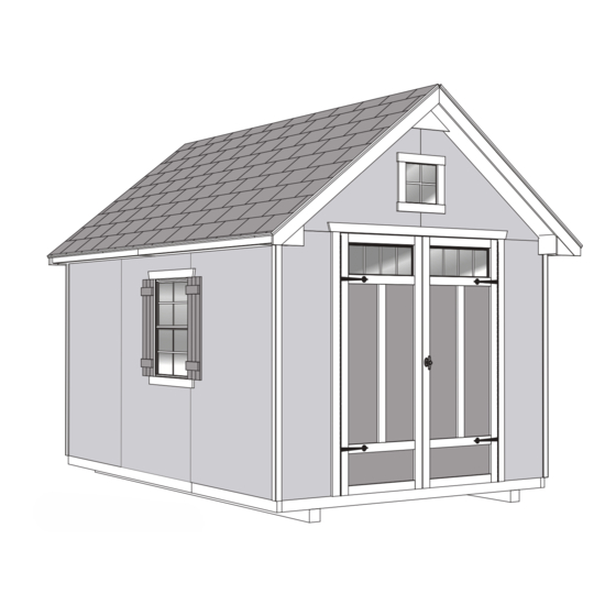
- Page 3 16562 08-04-2017 ASSEMBLY MANUAL A Backyard Products Company OAKRIDGE 8' x 12' (244 x 366 cm) ACTUAL FLOOR SIZE IS 96 x 140-5/8" (243,8 x 357,2 cm) KEEP THIS MANUAL FOR FUTURE REFERENCE Window Location Optional IMPO RTA N T! READ INSTRUCTIONS THOROUGHLY PRIOR TO BEGINNING ASSEMBLY. BEFORE YOU BEGIN • BUILDING RESTRICTIONS AND APPROVALS Be sure to check with local building department and homeowners association for specific restrictions and/ or requirements before building.
- Page 4 TOOLS Required Optional Phillips ❑ Tool Belt/ ❑ Utility Knife ❑ Screwdriver Nail Pouch Shingle Blades ❑ Drill / Driver ❑ 1/8" Drill Bit ❑ Tin Snips ❑ 1/4" Drill Bit ❑ Caulk Gun ❑ (for drip edge) 5/16" Drill Bit ❑...
- Page 5 ADDITIONAL MATERIALS FOUNDATION OR FLOOR MATERIALS • This shed kit includes a complete wood floor system. • This shed kit does not include ANY leveling materials. • See the FLOOR LEVELING section on page 7 for recommended methods and suggested materials to properly level your floor, as this will vary depending on your specific site. COMPLETING YOUR SHED You will need these additional materials: 3-TAB SHINGLES ......7 Bundles 1" GALVANIZED ROOFING NAILS..3 Lbs For shingles.
- Page 6 PARTS IDENTIFICATION AND SIZES Part identification WOOD SIZE CONVERSION CHART letters are stamped on some parts. Treated lumber is stamped: Nominal Board Size Actual Size 2" x 4"....1-1/2" x 3-1/2" (3,8 x 8,9 cm) 1" x 4"....3/4" x 3-1/2" (1,9 x 8,9 cm) 2" x 3"....1-1/2" x 2-1/2" (3,8 x 6,3 cm) 1"...
- Page 7 PARTS LIST continued... 2 x 3 x 18-3/8" (5,1 x 7,6 x 50,2 cm) 2 x 3 x 93" (5,1 x 7,6 x 236,2 cm) 2 x 4 x 96" (5,1 x 10,2 x 243,8 cm) 2 x 4 x 94-1/2" (5,1 x 10,2 x 240 cm) WITH WOOD GRAIN ON FACE 7-1/4 x 18-1/4"...
- Page 8 WALL PANEL & DOORS PARTS LIST 3/8 x 48 x 72" 3/8 x 44-5/8 x 72" LEFT DOOR RIGHT DOOR 3/8 x 19-5/8 x 72" (1 x 121,9 x 182,9 cm) (1 x 113,3 x 182,9 cm) (1 x 49,8 x 182,9 cm) NAIL BOXES 3"...
- Page 9 FLOOR LEVELING OPTIONS There are multiple ways to level your floor frame. Our recommended leveling method is shown below. Leveling materials are not included in this kit. PREFERRED METHOD - 4x4 TREATED RUNNERS • 3" Screws angled into 4x4. • (2) at each point frame •...
- Page 10 CONCRETE FOUNDATION Your kit contains all materials to construct a wooden floor. If you choose to install your kit on a concrete slab refer to the diagram below. Treated Sill Plate Caulk between sill plate and concrete. 3-1/2" (8,9 cm) 4" (10,2 cm) Building Size Actual Size 8'x 12' (243,8 x 365,8 cm) 96" x 140-5/8" (243,8 x 357,2 cm) 96" (243,8 cm) 133-5/8" (339,4 cm)
- Page 11 FLOOR FRAME PARTS REQUIRED: 3" (7,6 cm) 2 x 4 x 92-5/8" (5,1 x 10,2 x 235,3 cm) Look for TREATED 2 x 4 x 93" (5,1 x 10,2 x 236,2 cm) Stamp 2 x 4 x 48" (5,1 x 10,2 x 121,9 cm) BEGIN Orient parts as shown on flat surface.
- Page 12 LEVEL AND SQUARE FLOOR FRAME Before attaching floor decking, it is important to level and square the floor frame. A level and square floor frame is required to correctly construct your shed. BEGIN See page 7 for the preferred floor leveling method. Use level and check the frame is level before applying floor panels.
- Page 13 FLOOR PANELS PARTS REQUIRED: 2" (5,1 cm) 5/8 x 48 x 96" (1,6 x 121,9 x 243,8 cm) Ensure your floor frame is square by installing one panel and squaring frame. BEGIN Attach the 48 x 96" panel with the rough side up (painted-grid lines side) with the 48" edge and corner flush to the floor frame (Fig A). Secure panel with two 2" nails in the corners.
- Page 14 FLOOR PANELS PARTS REQUIRED: x124 2" (5,1 cm) 5/8 x 48 x 96" 5/8 x 44-5/8 x 96" (1,6 x 121,9 x 243,8 cm) (1,6 x 113,3 x 243,8 cm) Continue installing panels with rough side up (painted grid lines). Position 44-5/8" panel in middle of floor frame. Use grid lines on panel for 2"...
- Page 15 IMPORTANT! Check the floor frame is level after installing floor panels. Re-level if needed. • The floor should be used as a stable work surface for wall construction. • Organize your assembly procedure during the build process HINT: to avoid over-handling of the walls. Right Wall Back wall Front wall Left wall (Your window location will be determined later during assembly.)
- Page 16 LEFT WALL FRAME PARTS REQUIRED: 3" (7,6 cm) 2 x 4 x 68" (5,1 x 10,2 x 172,7 cm) 2 x 4 x 68-5/8" (5,1 x 10,2 x 174,3 cm) 2 x 4 x 72" (5,1 x 10,2 x 182,9 cm) YOU MUST BUILD THE LEFT AND RIGHT SIDE WALLS EXACTLY AS SHOWN! LEFT RIGHT...
- Page 17 LEFT SIDE WALL PANELS PARTS REQUIRED: 2" (5,1 cm) 48 x 72" (121,9 x 213,4 cm) 3/4" GAUGE BLOCK LEFT RIGHT YOU WILL ASSEMBLE ONE AND ONE WALL SEPARATELY. Ensure your wall frame is square by installing one panel and squaring frame. Place 48 x 72" panel onto wall frame flush to top of frame with primed side up as shown. Use the gauge block to mark the 3/4"...
- Page 18 LEFT SIDE WALL PANELS PARTS REQUIRED: 2" (5,1 cm) 3/4" GAUGE BLOCK 48 x 72" 44-5/8 x 72" (121,9 x 213,4 cm) (121,9 x 213,4 cm) For squareness maintain flush and 3/4" measurement along panel edges. Place center 48" x 72" panel on frame as shown with primed side facing up. Flush 3/4"...
- Page 19 RIGHT WALL FRAME PARTS REQUIRED: 3" (7,6 cm) 2 x 4 x 68" (5,1 x 10,2 x 172,7 cm) 2 x 4 x 68-5/8" (5,1 x 10,2 x 174,3 cm) 2 x 4 x 72" (5,1 x 10,2 x 182,9 cm) BEGIN For right wall, orient parts on edge on floor.
- Page 20 RIGHT SIDE WALL PANELS PARTS REQUIRED: 2" (5,1 cm) 48 x 72" (121,9 x 213,4 cm) 3/4" GAUGE BLOCK Ensure your wall frame is square by installing one panel and squaring frame. Place 48 x 72" panel onto wall frame flush to top of frame with primed side up as shown. Use the gauge block to mark the 3/4" measurement on the wall stud. Secure panel with two 2"...
- Page 21 RIGHT SIDE WALL PANELS PARTS REQUIRED: 2" (5,1 cm) 3/4" GAUGE BLOCK 48 x 72" 44-5/8 x 72" (121,9 x 213,4 cm) (121,9 x 213,4 cm) For squareness maintain flush and 3/4" measurement along panel edges. Place center 48" x 72" panel on frame as shown with primed side facing up. Flush 3/4"...
- Page 22 BACK WALL FRAME PARTS REQUIRED: 3" (7,6 cm) 2 x 4 x 13" (5,1 x 10,2 x 33 cm) 2 x 4 x 34-1/4" (5 x 10,2 x 87 cm) 2 x 4 x 17-3/4" (5 x 10,2 x 45,1 cm) 2 x 4 x 89"...
- Page 23 BACK WALL PANELS PARTS REQUIRED: 2" (5,1 cm) 3/4" GAUGE BLOCK 3/8 x 48 x 72" (1 x 121,9 x 182,9 cm) Place panel with primed side up onto frames with a 3/4" gap as shown. Maintain flush to top of frame edge. Ensure 3/4" gap between top, middle and bottom of frames. Hold the measurements and secure with 2"...
- Page 24 BACK WALL PANELS PARTS REQUIRED: 2" (5,1 cm) 3/8 x 48 x 72" (1 x 121,9 x 182,9 cm) Place right panel flush to left panel with primed side up. Secure using 2" (5,1 cm) nails 6" (15,2 cm) apart on edges and 12"...
- Page 25 BACK WALL PARTS REQUIRED: 3" (7,6 cm) 2 x 4 x 94-1/2" (5,1 x 10,2 x 240 cm) BEGIN Center UN on back wall top plate and flush to inside of back of wall panel (Fig. A). While keeping UN flush, secure to top plate using eight 3" screws. Flush Fig. A CENTER ON TOP PLATE...
- Page 26 FRONT WALL PARTS REQUIRED: 3" (7,6 cm) 2 x 4 x 16-1/2" (5,1 x 10,2 x 41,9 cm) 2 x 4 x 68" (5,1 x 10,2 x 172,7 cm) 2 x 4 x 89" (5 x 10,2 x 226,1 cm) BEGIN Orient parts on edge on floor.
- Page 27 FRONT WALL PARTS REQUIRED: 3" (7,6 cm) 1-1/4 x 2-1/2 x 69" (3,2 x 6,3 x 175,3 cm) TEMPORARY SUPPORT 2" (5,1 cm) 3/8 x 19-5/8 x 72" (1 x 49,8 x 182,9 cm) Place 19-5/8" x 72" panel onto wall frame flush to SZ with primed side up as shown.
- Page 28 FRONT WALL PARTS REQUIRED: 3" (7,6 cm) 2 x 3 x 84" (5,1 x 7,6 x 213,4 cm) Center FW on the 2-1/2" side of SZ flush to edge (Fig. A, B). Secure using five 3" screws on angle spaced evenly. FINISH You have finished building your front wall. Fig. A Flush Flush to 2x4...
- Page 29 RIGHT SIDE WALL INSTALLATION PARTS REQUIRED (TEMPORARY): 3" (7,6 cm) 2 x 4 x 94-1/2" (5,1 x 10,2 x 240 cm) 3" (7,6 cm) 2" (5,1 cm) BEGIN Stand right sidewall on floor. It is important to secure the right sidewall in the following order. ENSURE 20-5/8" MEASUREMENT IS TOWARD BACK OF SHED Center right sidewall assembly on the 140-5/8"...
- Page 30 LEFT SIDE WALL INSTALLATION PARTS REQUIRED (TEMPORARY): 3" (7,6 cm) 2 x 4 x 94-1/2" (5,1 x 10,2 x 240 cm) 3" (7,6 cm) 2" (5,1 cm) BEGIN Stand left sidewall on floor. It is important to secure the left sidewall in the following order. ENSURE 20-5/8" MEASUREMENT IS TOWARD BACK OF SHED.
- Page 31 BACK WALL INSTALLATION PARTS REQUIRED: 3" (7,6 cm) 2" (5,1 cm) 1-1/2" (3,8 cm) BEGIN Stand back wall on floor. It is important to secure the back wall in the following order. Set back wall on side wall top plates and secure using two 3" screws on each side (Fig A). Set back wall on side wall top plates and secure using two 3"...
- Page 32 FRONT WALL INSTALLATION PARTS REQUIRED: 2" (5,1 cm) 3" (7,6 cm) 1-1/2" (3,8 cm) 3" (7,6 cm) Stand front wall on floor. BEGIN It is important to secure the frontwall in the following order. Center front wall on floor side-to-side. Secure top plate to side walls using two 3" nails (Fig. A, B, E ). Nail front wall panels to side wall using 1-1/2"...
- Page 33 RAFTERS PARTS REQUIRED: x132 3" (7,6 cm) 2" (5,1 cm) OSB OR WOOD GRAIN 7-1/4 x 18-1/4" (18,4 x 46,4 cm) 2 x 3 x 7-7/8" (5,1 x 7,6 x20 cm) 2 x 4 x 68-7/16" (5,1 x 10,2 x 173,8 cm) TEMPORARY SUPPORT ¸ BEGIN Place one DY against back wall inner panel as shown.
- Page 34 RAFTERS PARTS REQUIRED: 3" (7,6 cm) (1) GUSSET Preassembled Preassembled ¸ BEGIN Locate first (1) GUSSET rafter directly over front stud, flush to inside of front wall panels, and tight to side wall (Fig. A, B). Face gusset inward. Rest notch on top plate. Secure rafter to top plate with two 3" screws above notch (Fig. A , B) . Place remaining rafters on top plate, aligned over studs as shown and secure with 3"...
- Page 35 FRONT WALL GABLE PARTS REQUIRED: 1-1/2" (3,8 cm) 2 x 4 x 4-5/8" (5,1 x 10,2 x 11,7 cm) 2 x 3 x 18-3/8" (5,1 x 7,6 x 50,2 cm) 2 x 3 x 10" (5,1 x 7,6 x 25,4 cm) TEMPORARY SUPPORT 2 x 3 x 11-7/8"...
- Page 36 BACK WALL GABLE PARTS REQUIRED: 1-1/2" (3,8 cm) 2 x 3 x 18-3/8" (5,1 x 7,6 x 50,2 cm) TEMPORARY SUPPORT 2 x 4 x 35-3/4" (5,1 x 10,2 x 90,8 cm) BEGIN Orient parts on flat as shown. Place LEFT back gable panel on RZ as shown and secure using 1-1/2" nails, 6" apart. Place RIGHT back gable panel on RZ and flush to left panel.
- Page 37 FRONT WALL GABLE PARTS REQUIRED: 1-1/2" (3,8 cm) Preassembled BEGIN Caulk on top of front wall panels first as shown. Place front gable assembly centered on front wall panel and flush to rafter peak (Fig. A). Secure front gable panels into top plate using 1-1/2" nails, 6" (15,2 cm) apart. While supporting rafter and assembly, secure gable panels to rafter using 1-1/2"...
- Page 38 BACK WALL (Gable Z-Strip) PARTS REQUIRED: 2" (5,1 cm) 96" (243,8 cm) Z-STRIP BEGIN Center Z-Strip on back wall panels (Fig. A). Secure to UN using seven 2" finish nails, 16" apart Fig. A FINISH You have finished attaching your Gable Z-Strip. 2" (5,1 cm) Finish Nails CENTER ON WALL PANELS 16"...
- Page 39 BACK WALL GABLE PARTS REQUIRED: 1-1/2" (3,8 cm) Preassembled BEGIN Center back wall gable assembly on z-strip. Gable panels should be flush to wall panel as shown (Fig. A). While keeping panels flush, secure gable assembly to UN using 1-1/2" nails, 6" (15,2 cm) apart. FINISH You have finished attaching your back wall gable panels.
- Page 40 LOFT SUPPORTS PARTS REQUIRED: 3" (7,6 cm) 2 x 4 x 94-1/2" (5,1 x 10,2 x 240 cm) BEGIN Center first loft support UN on top plate and flush against rafter as shown (Fig. A). Secure UN to rafter using four 3" screws (Fig. A). Center second loft support UN on top plate and 13"...
- Page 41 SHELF & WORKBENCH PARTS REQUIRED: 3" (7,6 cm) 2 x 3 x 18-3/8" (5,1 x 7,6 x 50,2 cm) 3" (7,6 cm) 2 x 3 x 93" (5 x 7,6 x 236,2 cm) BEGIN Place shelf support WJ at same height as horizontal wall brace and secure using two 3"...
- Page 42 SHELF & WORKBENCH PARTS REQUIRED: 3" (7,6 cm) 2 x 4 x 96" (5 x 10,2 x 243,8 cm) Measure and mark for workbench support TP up from the floor 35-3/4". Secure TP using two 3" nails into studs as shown. BACK WALL MARK MARK...
- Page 43 SHELF & WORKBENCH PARTS REQUIRED: 1-1/4" (3,2 cm) 7/16 x 11-7/8 x 88-7/8" (1,1 x 30,2 x 225,7 cm) 1-1/2" (3,8 cm) 7/16 x 23-7/8 x 88-7/8" (1,1 x 60,6 x 225,7 cm) Place 11-7/8" shelf panel and 23-7/8" workbench panel on support and fit into groove. Secure front of panels with 1-1/4"...
- Page 44 LOFT PANEL PARTS REQUIRED: 2" (5,1 cm) 7/16 x 35-7/8 x 82" (1,1 x 91,1 x 208,3 cm) BEGIN Place loft panel onto the three loft supports centered from side-to-side and flush with the back wall panel. Fit panel into gap. IMPORTANT! Use only SIX 2"...
- Page 45 BACK GABLE TRIM PARTS REQUIRED: 3" (7,6 cm) 2 x 4 x 69-7/8" (5,1 x 10,2 x 177,5 cm) 1-1/4" (3,2 cm) BEGIN Position one WW flush to back gable panel edge and center with panel seam (Fig. A) . Attach trim with ten 1-1/4" screws from inside approximately 7"...
- Page 46 FRONT WALL OVERHANG FRAMING PARTS REQUIRED: 3" (7,6 cm) 2 x 3 x 68-7/16" (5,1 x 7,6 x 173,8 cm) 2 x 3 x 7-7/8" (5,1 x 7,6 x 20 cm) BUILD FOUR OVERHANG FRAMES. BEGIN Orient parts on flat as shown. Ensure WE is oriented with 4" flat edge contacting DY. Secure DY flush to WE using one 3"...
- Page 47 FRONT WALL OVERHANG PARTS REQUIRED: 3" (7,6 cm) 3/8 x 2 x 5" 2" (5,1 cm) (1 x 5,1 x 30,2 cm) Pre-assembled BEGIN Position 2 x 5" spacer flush to front of rafter and wall panel. Secure using two 2" (5,1 cm) nails (Fig. A).
- Page 48 FRONT WALL OVERHANG PARTS REQUIRED: 1-1/4" (3,2 cm) 3/8 x 7-7/8 x 57-7/8" (1 x 20 x 147 cm) Ensure overhang boards meet at peak (Fig. A). Position right 57-7/8" overhang board Primed Side Down flush to front wall and framing assembly (Fig A). Secure using six 1-1/4" screws. Position left 57-7/8" overhang board Primed Side Down flush to front wall, framing assembly and right overhang board (Fig. A).
- Page 49 FRONT WALL OVERHANG PARTS REQUIRED: 1-1/4" (3,2 cm) 3/8 x 7-7/8 x 7-7/8" (1 x 20 x 20 cm) Position right 7-7/8" overhang board Primed Side Down flush to front wall and soffit block (Fig. A). Secure using two 1-1/4" (3,2 cm) screws Position left 7-7/8" overhang board Primed Side Down flush to front wall and soffit block (Fig. B).
- Page 50 FRONT WALL OVERHANG PARTS REQUIRED: 1-1/4" (3,2 cm) 3/8 x 5-13/16 x 7-7/8" (1 x 14,8 x 20 cm) Position right 5-13/16" overhang board Primed Side Out flush to front wall and previously installed overhand boards (Fig. A). Secure using two 1-1/4" screws Position left 5-13/16" overhang board Primed Side Out flush to front wall and previously installed overhand boards (Fig. B).
- Page 51 FRONT WALL OVERHANG PARTS REQUIRED: 3" (7,6 cm) 1-1/4" (3,2 cm) Preassembled Position overhang framing flush to front of overhang boards. (Fig. A). Secure bottom of overhang framing first as shown using three 1-1/4" screws. Continue securing overhang framing while traveling toward peak as shown Repeat Step 10 on opposite side.
- Page 52 FRONT WALL OVERHANG PARTS REQUIRED: 2" (5,1 cm) 19/32 x 4 x 69-7/8" (1,5 x 10,2 x 177,5 cm) 19/32 x 4 x 69-7/8" (1,5 x 10,2 x 177,5 cm) Position WML with primed side out and flush to peak and overhang framing as shown (Fig. A).
- Page 53 SOFFIT NAILER PARTS REQUIRED: USE AS GAUGE BLOCK 2" (5,1 cm) 2 x 3 x 5-1/8" (5,1 x 7,6 x 13 cm) 1 x 2 x 43-1/2" (2,5 x 5,1 x 110,5 cm) 1 x 2 x 96" (2,5 x 5,1 x 243,8 cm) BEGIN Place a square flush to bottom side of rafter and side wall (Fig. A).
- Page 54 SOFFIT BLOCK PARTS REQUIRED: 2-1/2" (6,4cm) 2 x 3 x 5-1/8" (5,1 x 7,6 x 13 cm) BEGIN Position WD flush against side wall and bottom of WS. Attach with three 2-1/2" screws as shown (Fig. A). Repeat Step 1 for opposite side (Fig. B). FINISH You have finished attaching your back wall soffit block. Flush Flush (3) 2-1/2"...
- Page 55 SOFFIT PARTS REQUIRED: 1-1/4" (3,2 cm) 3/8 x 5-3/16 x 69-3/8" (1 x 13,2 x 176,2 cm) 3/8 x 5-3/16 x 72" (1 x 13,2 x 182,9 cm) BEGIN Place 72" soffit board primed side down on bottom side of rafter and nailer (Fig. A) and flush to front overhang (Fig. B) and side wall.
- Page 56 BACK WALL SOFFIT CAP PARTS REQUIRED: 2" (5,1 cm) 19/32 x 6-15/16 x 5-1/2" (1,5 x 17,6 x 13,4 cm) 19/32 x 6-15/16 x 5-1/2" (1,5 x 17,6 x 13,4 cm) BEGIN Position LEFT corner soffit cap primed side up on back wall with 6-15/16" measurement down and flush to bottom of soffit board as shown.
- Page 57 ROOF PANELS PARTS REQUIRED: 2" (5,1 cm) 7/16 x 8-7/8 x 70" (1,1 x 22,5 x 177,8 cm) 3/4" GAUGE BLOCK 7/16 x 22 x 96" (1,1 x 55,9 x 243,8 cm) 7/16 x 22 x 46-1/2" (1,1 x 55,9 x 118,1 cm) 7/16 x 48 x 94-1/2"...
- Page 58 ROOF PANELS PARTS REQUIRED: x228 2" (5,1 cm) Fig. E Keep spacing between the center of the NOTE: Measurement from outside of trim. rafters at the lower edge of the panel and secure with one 2" nail into each 22-1/2" 24" 24" 24"...
- Page 59 COLLAR TIES PARTS REQUIRED: 3" (7,6 cm) 2 x 4 x 48" (5,1 x 10,2 x 121,9 cm) BEGIN Position and level collar tie on second and fourth rafter from back wall. HINT: For best appearance install collar tie on rafter facing away from door opening. Glue collar tie and attach with 3"...
- Page 60 LOFT PANEL PARTS REQUIRED: 2" (5,1 cm) BEGIN Continue nailing 2" nails in each loft panel support as shown. FINISH You have finished your loft panel. 2" (5,1 cm) Nails Attention: Load not to exceed 300 lbs evenly distributed across loft.
- Page 61 FRONT WALL DECORATIVE TRIM PARTS REQUIRED: 2" (5,1 cm) 5-11/16 x 7-13/16" (14,4 x 19,8 cm) 7-1/4 x 18-1/4" (18,4 x 46,4 cm) WITH WOOD GRAIN ON FACE 5-11/16 x 7-13/16" (14,4 x 19,8 cm) BEGIN Position right corner soffit cap Primed Side Out flush to bottom of overhang as shown.
- Page 62 FASCIA PARTS REQUIRED: 2" (5,1 cm) 3/8 x 2-3/4 x 80-1/4" (1 x 7 x 203,8 cm) 3/8 x 2-3/4 x 69" (1 x 7 x 175,3 cm) ¸ BEGIN Attach fascia boards flush to rafters and flush to roof panels (Fig. A) using two 2" finish nails at each rafter and four 2"...
- Page 63 DOORS PARTS REQUIRED: 3" (7,6 cm) 1-1/4 x 2-1/2 x 69" (3,2 x 6,3 x 175,3 cm) 1-5/8" (4,1 cm) 1 x 3 x 5" (2,5 x 7,6 x 12,7 cm) Left Door Assembled Right Door Assembled Orient parts as shown on flat surface. 3/8"...
- Page 64 DOORS PARTS REQUIRED: 3" (7,6 cm) 1-1/4 x 2-1/2 x 69" (3,2 x 6,3 x 175,3 cm) Attach temporary support OO as a ledger board flush under wall panels for doors to rest on, using three 3" screws (Fig. A) . Flush against wall panels.
- Page 65 DOOR TRIM PARTS REQUIRED: 3/4" (1,9 cm) x11 2" (5,1 cm) Bagged seperately / special coating 19/32 x 3 x 23" (1,5 x 7,6 x 58,4 cm) 64" Metal Threshold 19/32 x 3 x 44-1/8" (1,5 x 7,6 x 112,1 cm) 3/4"...
- Page 66 DOOR WINDOWS PARTS REQUIRED: 3/4" (1,9 cm) Transom Window Left Door Right Door ¸ BEGIN Apply high quality exterior-grade caulk behind frame near edge before installing to seal window. From back side of door, position window in opening and ensure square with door edge. Use four screws to secure each window.
- Page 67 DOOR STIFFENERS PARTS REQUIRED: 2" (5,1 cm) 1-1/4 x 2-1/2 x 69" (3,2 x 6,3 x 175,3 cm) BEGIN Center OO vertically on the left door in the door opening flush with the edge of door (Fig. A). Secure using (7) 3" screws through outside trim into OO (Fig. B) Repeat Steps 1-2 to install OO on right door.
- Page 68 DOOR HARDWARE PARTS REQUIRED: 1" (2,5 cm) 5/16" (0,8 cm) Drill Bit BEGIN Place bolt onto OO in open position with bolt end 3/8" down from frame. Bolt is open when loop is contacting base (Fig A) . Mark and pre-drill holes for screws. Install bolt with screws supplied and drill 5/16"...
- Page 69 DOOR HARDWARE / DECORATIVE HINGES PARTS REQUIRED: 1-1/2" (3,8 cm) 1/2" (1,3 cm) Drill Bit 3/4" (1,9 cm) 1/4" (0,6 cm) Drill Bit BEGIN Measure and mark location of hole on outside of right door as shown (Fig. A) . Pre-drill hole with 1/4" drill. Re-drill hole with 1/2"...
- Page 70 GABLE WINDOW PARTS REQUIRED: 1-1/4" (3,2 cm) Gable Window ¸ BEGIN Apply high quality exterior-grade caulk behind frame near edge before installing to seal window. From outside of shed, position window in opening and level. Use four screws at corners of windows. Do not overtighten screws.
- Page 71 GABLE WINDOW WINDOW INSTALL TRIM PARTS REQUIRED: PARTS REQUIRED: 1/2" (1,3 1 x 2 x 11" (2,5 x 5,1 x 27,9 cm) 19/32 x 2-1/2 x 11-1/2" (1,5 x 6,4 x 29,2 cm) 2" (5,1 cm) 1 x 2 x 14" (2,5 x 5,1 x 35,6 cm) 19/32 x 2-1/2 x 17"...
- Page 72 GABLE WINDOW PARTS REQUIRED: 3/4" (1,9 cm) From inside, snip protruding finish nails. Install 3/4" screws into backside of vertical window trim EFA from inside as shown. Do not screw into window flange. FINISH You have finished installing your window. INSIDE OF SHED 3/4" (1,9 cm) Screws...
- Page 73 TRIM PARTS REQUIRED: 2" (5,1 cm) 3/8 x 1-3/4 x 67-3/4" (1 x 4,4 x 172,1 cm) ¸ BEGIN Attach one trim flush under soffit panel and along adjacent wall (Fig. A, B) using two 2" (5,1 cm) finish nails as shown. Position second trim flush to top and edge of previously installed trim (Fig. A, B). Secure using two 2"...
- Page 74 WINDOW SHUTTERS PARTS REQUIRED: 1" (2,5 cm) 19/32 x 2-1/2 x 7-1/2" (1,5 x 6,3 x 19,1 cm) 19/32 x 3 x 30-1/8" (1,5 x 7,6 x 76,5 cm) BEGIN Position shutter parts AZ and CCR primed side-down on floor as shown. Attach slats AZ using 1"...
- Page 75 LARGE WINDOW PARTS REQUIRED: 3" (7,6 cm) Inside View of Wall 1-1/4" (3,2 cm) 30” 2 x 4 x 22-1/2" (5,1 x 10,2 x 57,1 cm) Large Window (76cm) BEGIN You can place your window within Choose your window location. three locations on either side of shed 3/8”...
- Page 76 LARGE WINDOW SHUTTERS PARTS REQUIRED: 2" (5 cm) 1-1/4" (3,2 cm) 19/32 x 3 x 30" (1,5 x 7,6 x 76,5 cm) 19/32 x 3 x 28-1/2" (1,5 x 7,6 x 72,4 cm) Mark Locate one shutter centered on marks as shown. CENTER CENTER Attach one shutter using a 2"...
- Page 77 HOOK & EYE PARTS REQUIRED: Hook ¸ BEGIN Install hooks into endcap and into 2 x 3" behind (Fig.A). Swing door open to locate eye. FINISH You have finished installing your hook and eye. Fig. A Hook 2" 1" Install hook on inside face 2" up from bottom and 1" in from inside face into solid 2 x 3"...
- Page 78 VENTS PARTS REQUIRED: 1/2" (1,3 cm) 8 x 16" (20,3 x 35,6 cm) You can place your side wall vent on either side of shed ¸ BEGIN Locate and mark for one vent in side wall and one vent in the back wall gable as shown. Caulk behind vent flanges.
- Page 79 PAINT & CAULK - NOT INCLUDED - • Use acrylic latex caulk that is paintable. Caulk at all horizontal and vertical seams, between the trim and walls, and all around the door trim. • Use a high quality exterior acrylic latex paint. When painting your building, there are a few key areas that can be easily overlooked that must be painted: •...
- Page 80 SHINGLES - NOT INCLUDED - • Follow directions provided by manufacturer and these instructions. Familiarize yourself with a 3-Tab Shingle. Notch Notch SHINGLE NAIL PATTERN 1/2" 1" Sealing Strip 1" (1,3 cm) (2,5 cm) (2,5 cm) Half A Rain Slot Full Rain Slot NAILS NEVER DRIVE FASTENERS INTO OR ABOVE SEALING STRIPS. BEGIN Install first starter row upside down and color up with a 1" overhang at back and bottom of roof panel. Use (4) nails per shingle. Starter row must be straight and level all the way across with lower edge of roof deck.
- Page 81 SHINGLES continued... Beginning at front of shed, install first row of shingles with notch at 1" past roof edge or flush with drip edge. Roof Deck FRONT OF BACK OF SHED SHED 1" (2,5 cm) Flush with starter row. Notch - or - Drip Edge Flush with starter row. Notch Install second row of shingles flush at top of first row's rain slots.
- Page 82 SHINGLES continued... Continue installing rows of shingles to the peak. At the peak make sure there is a maximum of 5" or less to the rain slot, as shown below. If shingles overlap at ridge cut to peak with a utility knife. 5"...
- Page 83 SHINGLES - RIDGE CAP • You will finish off the top of the roof with a ridge cap made from shingles. BEGIN Cut shingles into THREE pieces. Hint: Use cut-off pieces first. 2" 2" (5 cm) (5 cm 2" 2" 2"...
- Page 84 SHINGLES - RIDGE CAP continued... Continue installing ridge cap to back of roof. Make sure there is 4" between the shingle-color and edge of shingles. 4" (10 cm) Trim cap off flush to shingles When you have 4" minimum of shingle color cut one piece to cap your roof. Cut at top of rain slot.
- Page 85 (This page intentionally left blank.)
- Page 86 (This page intentionally left blank.)
- Page 87 (This page intentionally left blank.)
- Page 88 WARRANTY REGISTRATION Please complete your warranty registration to properly validate your warranty. Register your product online at: www.OnlineWarranty.net LIMITED CONDITIONAL WARRANTY* Backyard Storage Solutions, LLC warrants the following: Every product is warranted from defects in workmanship and manufacturing for 1 year. All accessories, hardware and metal components are warranted for 2 years.
Need help?
Do you have a question about the OAKRIDGE 8 x 12 and is the answer not in the manual?
Questions and answers